As originally conceived, my "more storage room" desire was to be achieved by simply adding a shelf above the top of the filing cabinet in the study. I therefore spent some time thinking about ways to somehow make it more interesting than just a board mounted to the wall but didn't really get too far. However while contemplating fancy shelves and looking at that part of the room, it occurred to me that I could clean up the area beside the filing cabinet which was currently a useful but very messy zone. It was mostly books of Sue's waiting to be read or consulted and chargers for various battery-powered devices. Some cupboards for the books and a built-in charging area that was less flammable than a carpet seemed like a good approach. I could then provide storage for turned vessels on shelves above.
Almost all display cabinets are like the classic China cabinet with a square frame and glass but they usually have corners and door frames that block the view. I decided instead to go with open shelves for maximum visibility. That wouldn't help keep dust off but it also wouldn't be any worse than my current top-of-filing-cabinet storage. The wood items are not very heavy so cantilevered shelves would likely have adequate strength.
Square cabinets seemed pretty boring so I added a curve to the front and decided to use doors with contrasting pierced panels. One area would be left open and used for device charging. A ceramic floor would provide a bit of heat and fire resistance in the unlikely event of a battery failure. As for what wood to use, the desks in our study are cherry so it made sense to use that for the cabinet as well. Of course plywood was used for structural stability in combination with solid cherry for the edging and door frames.
Contents:
• First, A Few Jigs
• The Cabinet Carcass
• Shelves
• Cabinet Sides
• The Back
• More Carcass
• Door Frames
• Door Panels
• Mounting the Shelves
• Charging Station Base
• A Few Details
• Finishing
• Final Assembly
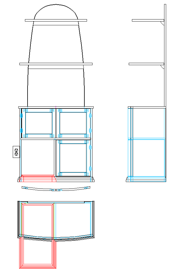
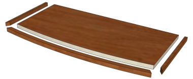
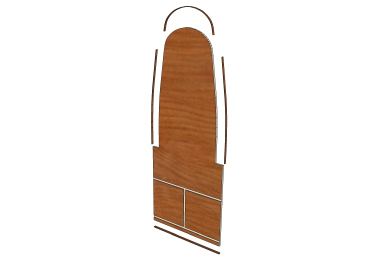
The overall plan
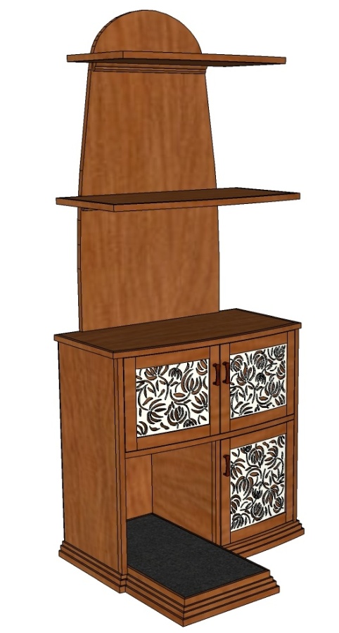
What it will ideally look like.
First, A Few Jigs
Next ↓ Previous ↑
I hadn't nailed down how to cut the curves on the shelves but I thought a pattern would be useful. So then I needed something to draw a smooth curve on the pattern and decided to use a beam compass. Finally I wanted a curved 2-piece press for making plywood for the cupboard door panels to confirm that it would impart the proper curve.
Blanks for a curve pattern and a curve press
I grabbed some "experienced" scraps of 3/8" MDF and glued them into something long enough for a curve pattern.
A couple two-by-four pieces also got glued together for the plywood press.
A couple two-by-four pieces also got glued together for the plywood press.
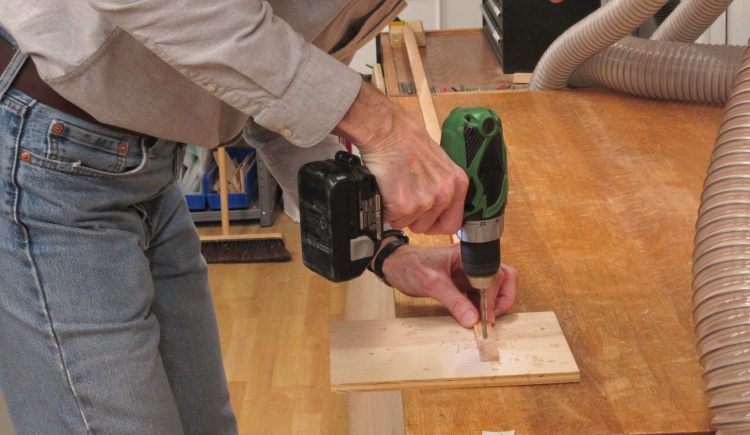
Drilling a pencil hole
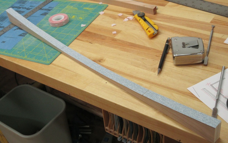
A couple of long wood strips taped securely together gave me a beam long enough for the 81" radius. It received a hole at the near end as shown here for a pencil and another at the far end for a pivot.
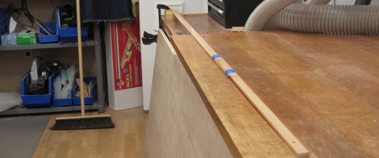
A beam compass for 81" radius
This shows the completed beam compass with a clamped-down 2x4 in the fuzzy distance holding a 1/4" dowel on which the beam pivots.
Drawing the curve onto the pattern
The 81" radius was traced on to the pattern blank which was then cut and sanded to the line.
The edge of the MDF was subsequently toughened up by applying super-glue which helps bond the wood fibres together.
The edge of the MDF was subsequently toughened up by applying super-glue which helps bond the wood fibres together.
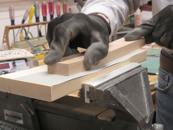
...and on the press
The plywood press was clamped into a Work-Mate and then had the curve traced on as well.
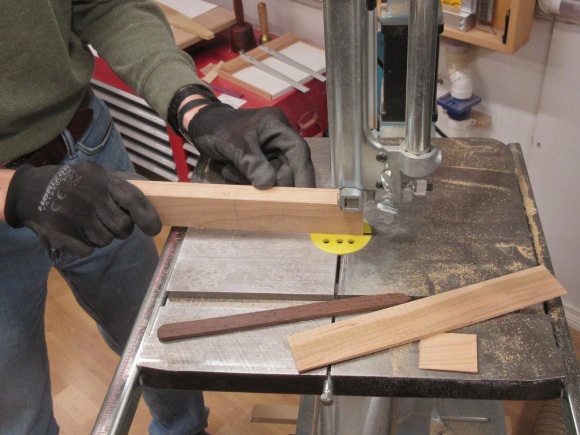
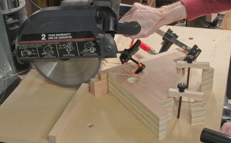
Cutting the press
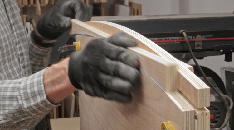
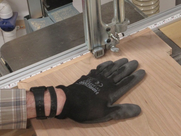
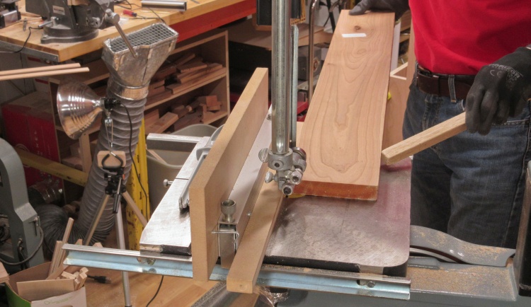
The press blank was cut to the curved line using the band saw with the aid of a taped-on handle.
This photo shows me cutting a thin strip out of the center of the press but I realized later that I could have gotten away with just a single cut.
This photo shows me cutting a thin strip out of the center of the press but I realized later that I could have gotten away with just a single cut.
Once they were made, the jigs were then set aside while I got to work on the actual cabinet.
The Cabinet Carcass
Next ↓ Previous ↑
The body of the cabinet in woodworking parlance is called a carcass (since it is made of dead wood?) and mine was constructed from plywood which had solid cherry applied to cover the unsightly exposed edges.
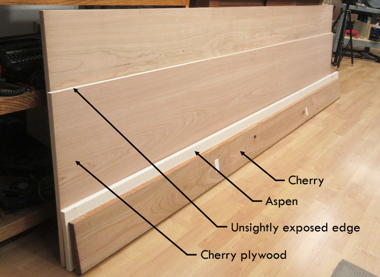
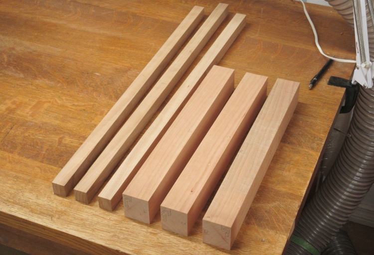
Wood for everything but the back
I needed a couple sheets of plywood for the cabinet plus solid cherry for trim.
I also wanted a light-coloured wood for the contrasting cupboard doors so I searched around Windsor Plywood for the whitest wood I could find and settled on the Aspen that's hiding behind the plank of cherry.
The plywood sheet was cut to a strategic width at the store to maximize yield of cabinet pieces while still fitting into my car. They had only one in stock so another trip a couple weeks later was necessary to furnish me with the second sheet.
~Aside~
My current car is a BMW 318i - your basic 4-door sedan with sporting pretensions. I was never a particular fan of BMW which apparently was unusual since I inferred from the salesman's comments that most people buying them have wanted one their whole lives. He seemed disappointed that I wasn't more excited when it finally arrived. But it just turned out to have the features I wanted and I was a bit surprised to find that it was a pretty practical vehicle; comfortable, decent ride, big trunk, 40/20/40 fold down rear seats for those days when you need to carry some plywood and of course my favourite feature - a heated steering wheel. I was a bit nervous about the lack of spare and the use of run-flat tires - you simply drive on a flat tire to the nearest service station and then buy a new set of tires since that usually ruins the run-flat. Fortunately I've been lucky and in 13 years of ownership I have had zero flats (if you ignore a slow leak in a winter tire).
I was able to carry the 48"-wide plywood sheets by cutting them into two pieces of 20 & 28 inch widths. Those fit into the trunk with the seats folded down although at 8' long of course they stuck out a couple feet. A pair of 2x4s sandwiching the plywood using bungees let me hold things together with the trunk closed as far as it would go.
Shelves
Next ↓ Previous ↑
The first sheet of plywood would be enough to make all the shelves and the cabinet sides. That would just leave the back which unfortunately would require another whole sheet of plywood.
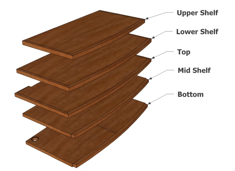
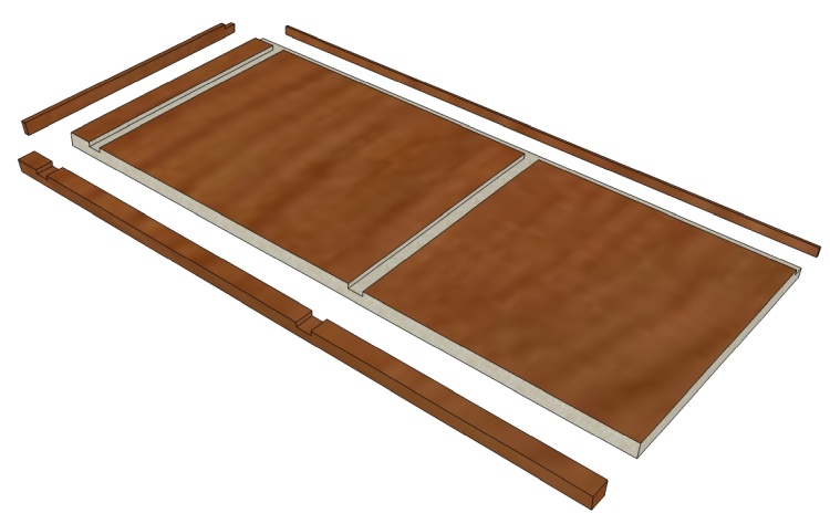
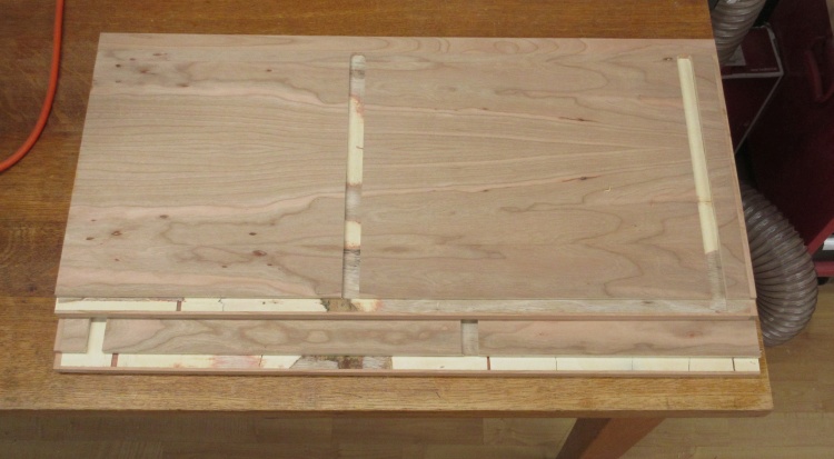
The annotated shelves
The cabinet used five shelves with the lower three forming parts of the cabinet. They all have curved fronts but need various amounts of solid-wood trim.
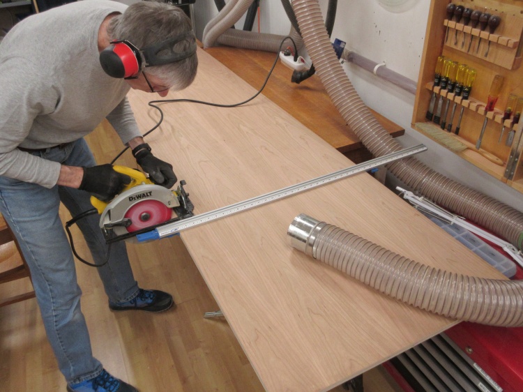
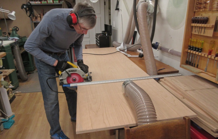
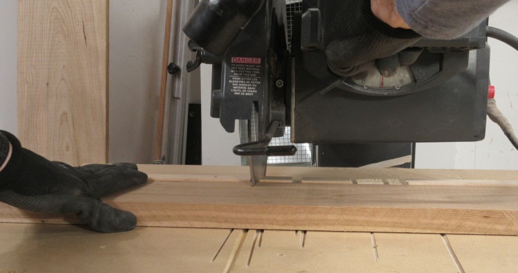
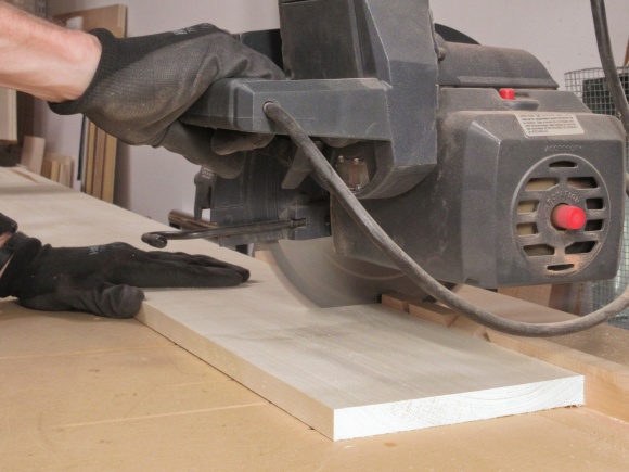
The "I don't have a table saw" cutting technique
The lack of a table saw (plus more importantly, the room to make use of it) means I needed to cut up the plywood another way. Both the band saw and the radial arm saw have significant limitations on the size of wood that they are effective on so I went with a hand tool.
Fortunately with a circular saw and a guide, I was able to make decent cuts to chop the plywood into pieces small enough to fit onto the band saw.
Fortunately with a circular saw and a guide, I was able to make decent cuts to chop the plywood into pieces small enough to fit onto the band saw.
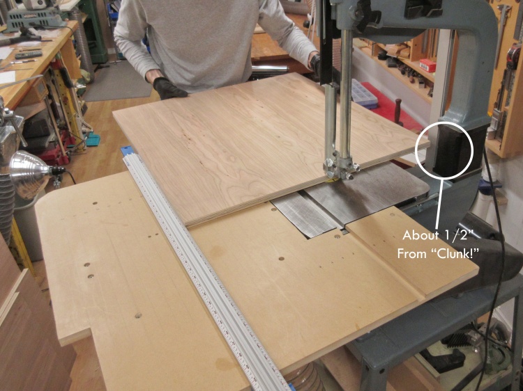
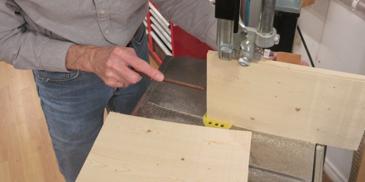
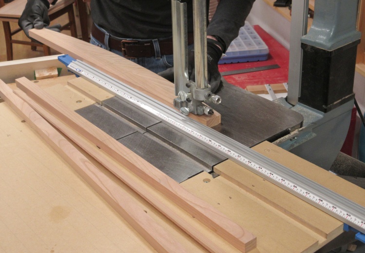
Cutting to width on the bandsaw
There was just enough clearance to cut the plywood into pieces a bit wider than the finished size.
Most of the pieces were similar widths to this one just due to the dimensions of the cabinet.
Most of the pieces were similar widths to this one just due to the dimensions of the cabinet.
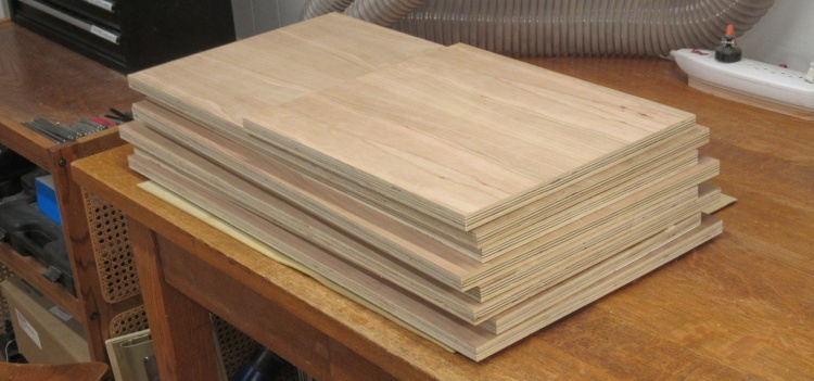
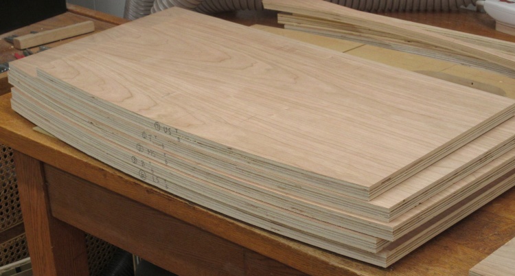
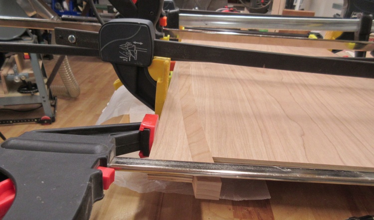
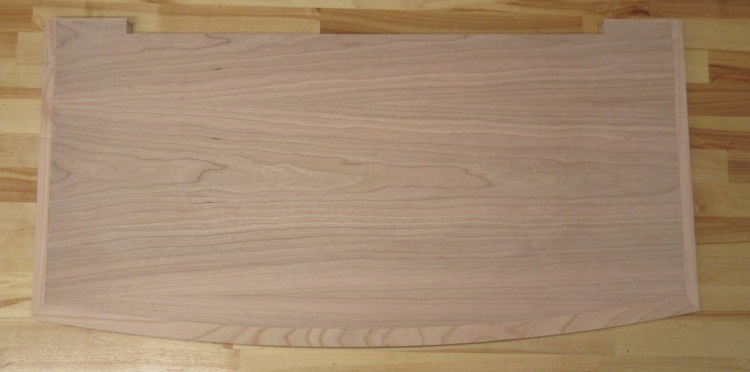
All the plywood pieces (except back) cut a bit oversized
This is the pile of roughly-cut-to-size plywood with a bit of extra left on to be able to trim them to the accurate finished size with my size-limited power saws.
Then I set up the band saw (for the longer dimension) or the radial arm saw (for the shorter dimension) to cut the pieces to the finished size. I left a tiny bit extra on the band saw cuts so I could use the jointer to clean up the rough edge it leaves.
Cutting to correct width
Cleaning up the edge
Cutting to correct length
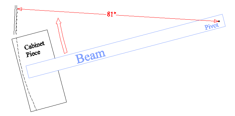
The cut-a-curve concept
Next was cutting curves for the front of the cabinet. This sketch shows the setup I used to cut them and it's conceptually similar to the beam compass previously used to draw the curves.
The curve radius was 81" so the pivot was positioned that distance from the band saw blade.
The curve radius was 81" so the pivot was positioned that distance from the band saw blade.
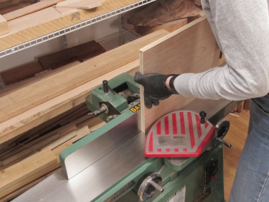
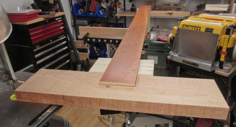
Big pivot spaced precisely from band saw blade
The pivot point was located at the jointer - an anchor I felt confident would stay in place - by clamping some wood to the fence and drilling a 1/2" socket hole at the top.
The overly-long steel rod went into the socket through a hole in the beam (which was a leftover scrap from kitchen renovations 19 years ago) and which was supported in the middle with a roller stand.
The overly-long steel rod went into the socket through a hole in the beam (which was a leftover scrap from kitchen renovations 19 years ago) and which was supported in the middle with a roller stand.

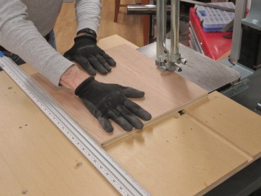
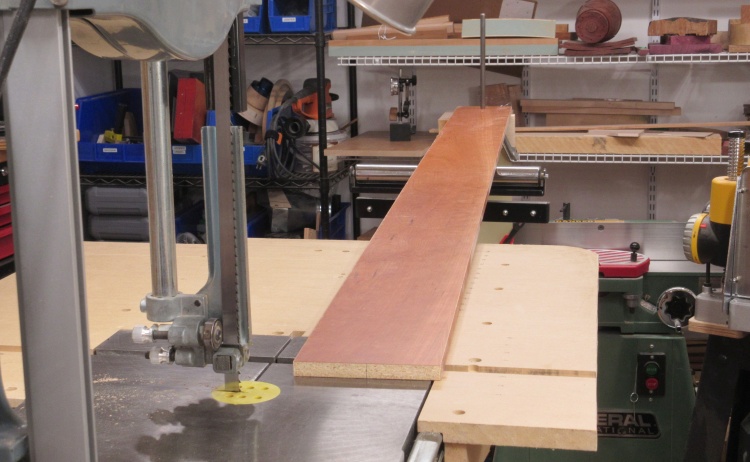
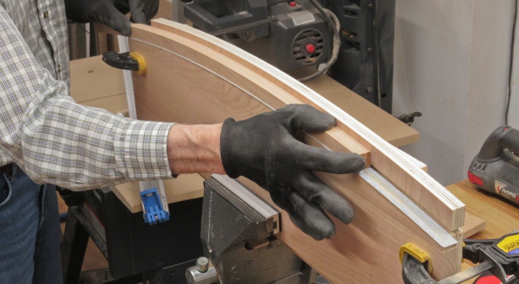
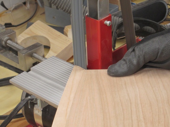
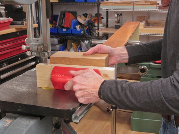
Taping plywood to the pivot
I used double-sided tape to hold the piece to be cut to the beam. The end of the beam was positioned exactly 2" from the near side of the blade so I could mark beforehand on the piece where it needed to go.
One swing and curve is cut
Then the piece was just swung past the blade. This shot shows the now-curved edge and the narrow cut-off piece.
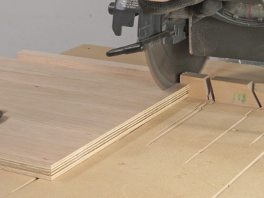
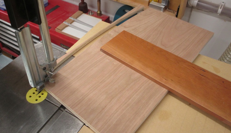
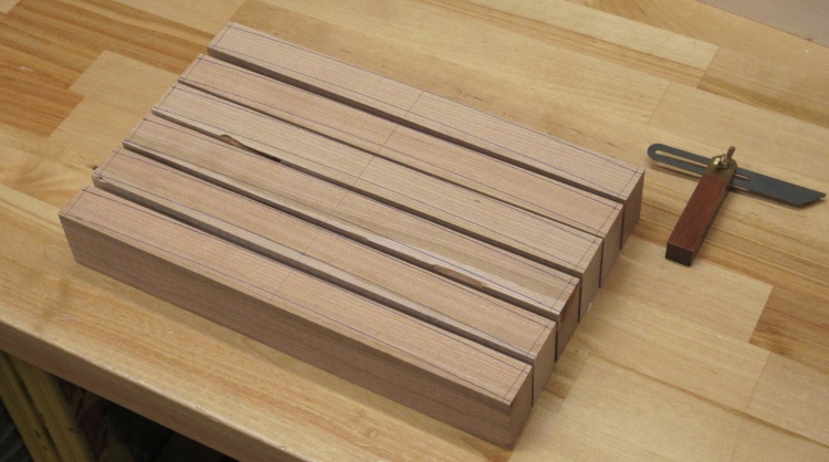
The five curved plywood pieces I'll need
There were five pieces that needed a curve and they are all cut and labelled on the table here.
Similarly-cut solid cherry for the front edges
I used exactly the same technique to cut the five solid-cherry trim pieces that would go on the curved edges of the plywood.
Now technically, the outside diameter of the 3/4"-wide trim pieces should have been 81.75" rather than 81" but I didn't bother to change it since it would have made only about 0.01" difference to the edges of the curve. Yah, we'll call that close enough.
Now technically, the outside diameter of the 3/4"-wide trim pieces should have been 81.75" rather than 81" but I didn't bother to change it since it would have made only about 0.01" difference to the edges of the curve. Yah, we'll call that close enough.
A sanding jig made from a plywood cut-off
The beam compass cutting technique produced very accurate and regular curves but the band saw always leaves a rough edge. It may have been OK to leave it as-is but sanding would help endure the plywood-to-trim joint was tight.
I used one of the plywood cut-offs with taped-on 120-grit sandpaper to make a shaped sanding form for the curves on the plywood.
I used one of the plywood cut-offs with taped-on 120-grit sandpaper to make a shaped sanding form for the curves on the plywood.

Plywood clamped to a guide that holds things vertical
To ensure the sanding produced a flat surface, I made another jig that clamped to the plywood. It was equipped with clearance for over-width sandpaper strips and provided a vertical surface against which the sanding form could slide to keep it exactly vertical, thereby keeping the sanded surface perfectly horizontal (one optimistically imagines).
Smoothing the curve of a plywood piece
And then it was just a matter of sliding the form back and forth until the worst of the saw-blade marks were removed.
The same approach used to sand the inside of the cherry trim pieces
Then for the inside curves of the trim pieces it was pretty much the same thing. For the sanding form I added sandpaper to the leftover solid cherry piece and slid the trim pieces over that.
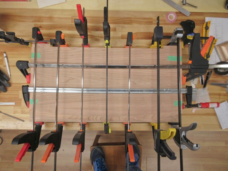
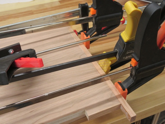
Gluing on one of the curved trim pieces
The cabinet bottom and inner shelf needed only the front trim on them as their sides would be embedded into the cabinet walls.
This photo shows an overly-long trim piece being glued and clamped to the cabinet bottom. One of those handy plywood cut-offs was inserted on the other side of the trim to provide a straight edge for the clamps.
This photo shows an overly-long trim piece being glued and clamped to the cabinet bottom. One of those handy plywood cut-offs was inserted on the other side of the trim to provide a straight edge for the clamps.
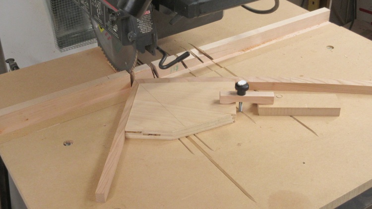
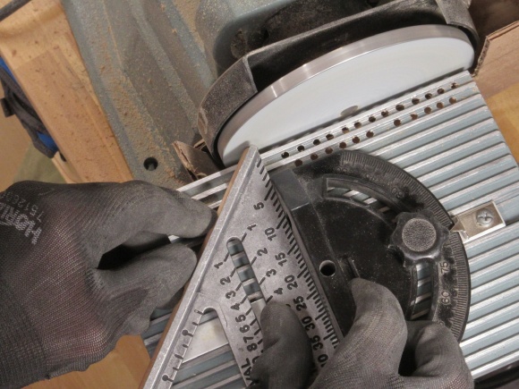
Radial-arm saw setup for a clean angled corner
The cabinet top and the shelves were a bit more involved since they needed trim on three sides. I decided to cut the trim with mitres as that seemed to look the most symmetrical.
Shelf with 3 trim pieces
A jig for the radial arm saw seemed like a fine solution for cutting a clean mitre.
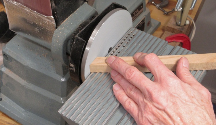
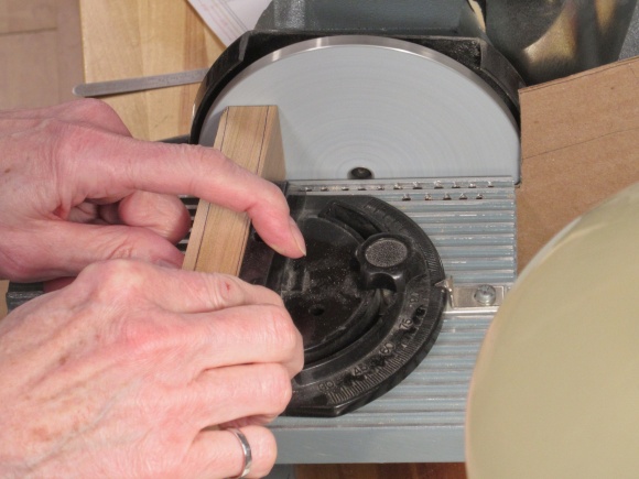
A more manual but better approach for a clean angled corner
Unfortunately, that didn't make a very good joint (not sure why) but I switched to cutting to an approximate angle and sanding for a close fit.
I had long ago removed the disc sander from my belt/disc sander since I didn't use it much but it's better than the belt for making a flat surface so I dug up the parts and stuck them back on.
I had long ago removed the disc sander from my belt/disc sander since I didn't use it much but it's better than the belt for making a flat surface so I dug up the parts and stuck them back on.
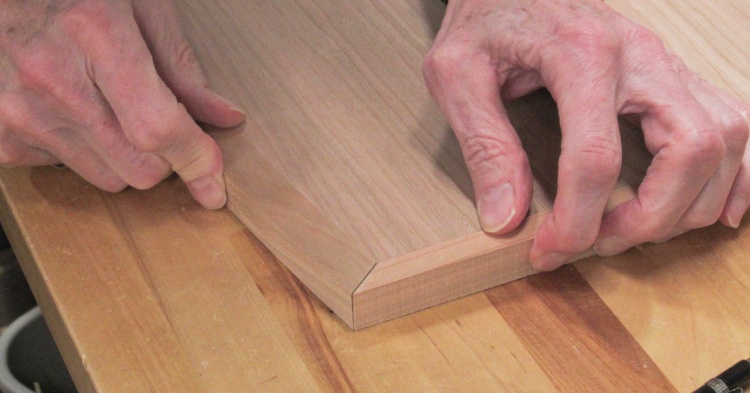
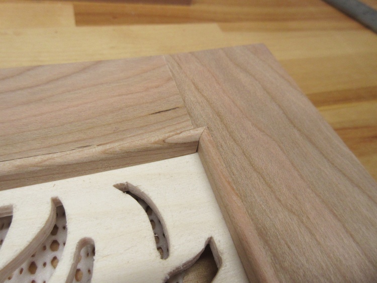
Checking a corner for fit (this one needs work)
I would try out the joint I was working on and then return to the sander if any adjustments were needed.
Gluing on curved-front and straight-side trim pieces
When the joints looked good I glued on all three trim pieces in one go.
Since it would be virtually impossible to have the trim the exact thickness of the plywood and also line it up perfectly, I instead made the trim pieces about .04" thicker than the plywood.
That meant that I needed to remove a bit to make to trim flush with the plywood. I ended up using a mixture of routing, the block plane seen here, spokeshaves and card scrapers. Those efforts were followed by sanding.
That meant that I needed to remove a bit to make to trim flush with the plywood. I ended up using a mixture of routing, the block plane seen here, spokeshaves and card scrapers. Those efforts were followed by sanding.
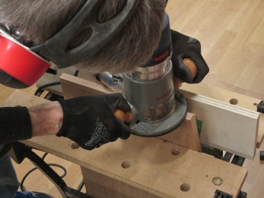
Routing side trim
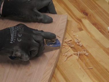
Planing curved trim
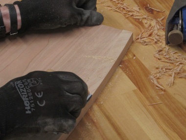
...and sanding as a final step
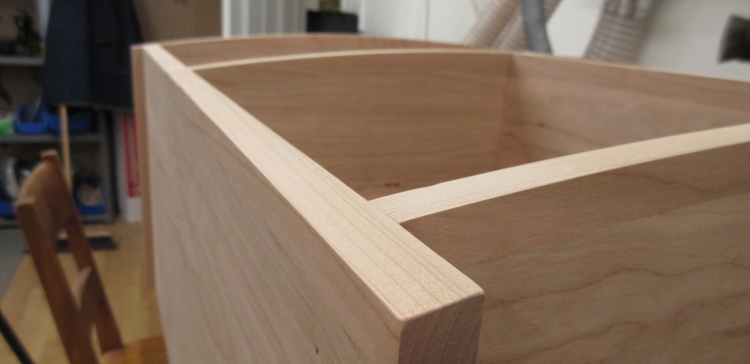
Case top with all trim in place
This shot shows the completed case top with all its trim in place.
That notch on the back edge fits around the narrower width of the back.
That notch on the back edge fits around the narrower width of the back.
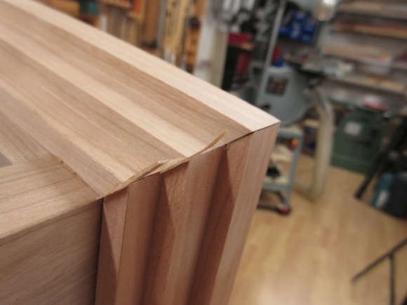
...except that left-side trim is pretty rough
Unfortunately the left-side plywood-to-trim joint was pretty ugly due to chipped veneer. That might have been OK on the underside but it was on the top side at the most obvious viewing height. Plus, I'd gouged the trim when routing.
Yah, this was going to need work.
Yah, this was going to need work.
I decided to cut off the trim and about 1 mm of the plywood which would get rid of most of the ugly bits. Then the plywood side would be sanded smooth, the bevel touched up and the trim replaced. That would make the top overhang 0.04" shorter on one side than the other but I figured that would be way less noticeable than the ugly joint.
Sawing off left-side trim
Sanding the edge smooth
Re-bevelling the front trim
Gluing on a new side trim piece
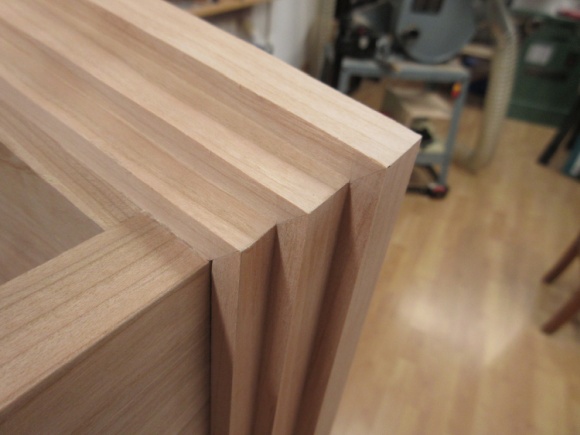
A more acceptable trim joint
And after all that, it looks decent. Whew.
The AC wire access
The plan for the cabinet's lower left quadrant was to have a charging station which meant I needed to get AC power into that area. I'd have to pass an AC plug out which would need a decent-sized hole. I decided to add the hole to the bottom piece which would get the plug into the cavity below the cabinet and then it could pass through a slot to get outside.
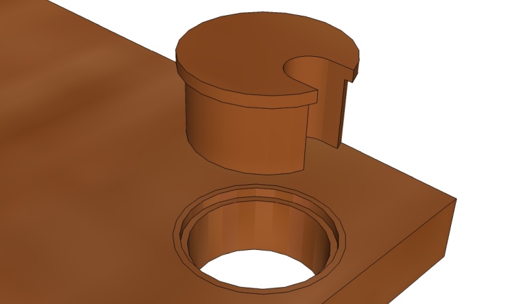
This sketch shows the AC-plug hole with a wooden plug equipped with a wire slot to fill most of the area.
This sketch shows the AC-plug hole with a wooden plug equipped with a wire slot to fill most of the area.
Of course I'd need a cherry liner for the hole in the plywood so that was turned on the lathe. Further lathe-work would yield a matching plug and then a bit of drill-and-saw work made a slot for the AC wire.

Drilling a 1.5"-diameter hole
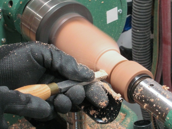
Turning a liner for the hole
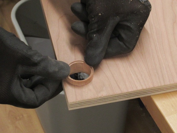
Checking the liner fit
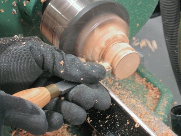
Turning the plug
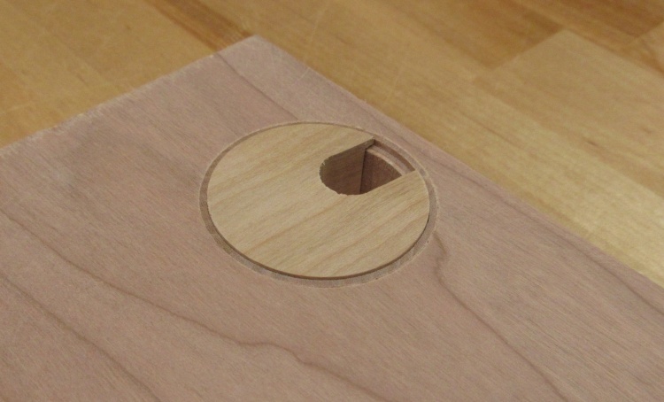
Hole with plug installed
This shows the hole with plug in place. Fit is good but the plug colour is totally different from the plywood. Good thing this is at the back corner of the cabinet (and covered with a ceramic tile).
Cabinet Sides
Next ↓ Previous ↑
The two sides were constructed in a similar manner to the shelves except that all the trim was rather easier, being straight.
A side with its trim
This sketch shows the three trim pieces needed for each side. I used thicknesses of 3/4" for the front, 1/4" for the bottom and 1/8" for the back.
The inner face also needs three routed slots that accept the two internal shelves and the back.
The inner face also needs three routed slots that accept the two internal shelves and the back.
Chopping up some straight trim for the sides
Making the trim was pretty simple.
Using a scraper to bring the trim flush
Here the trim pieces are in place and I'm making the front trim flush with the plywood, this time with a card scraper.
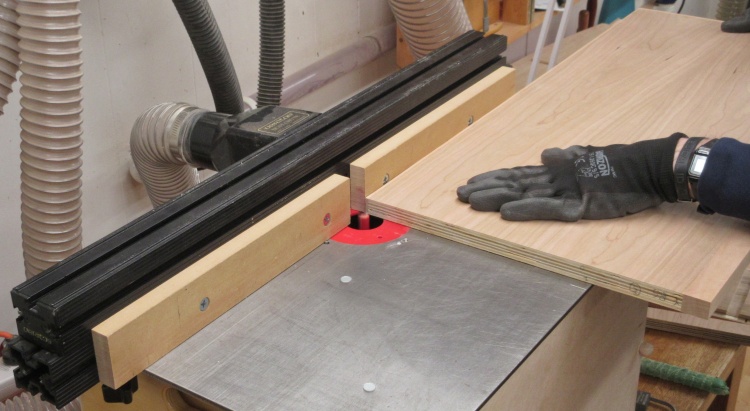
Starting to route edge rabbets
Routing the rabbets and slots was done on the router table. This took a couple passes since the 0.7" slots don't match a standard router bit diameter.
Sides with all routing done
This shot shows the post-routing inner faces of the two sides.
I wasn't very pleased with the actual construction of the cherry plywood. There were some voids and here you can see the results of inconsistent layer thickness - a consistent slot depth should show the same layer of veneer all over the board. That being said, it seemed to go together fine (after adjusting for the - sigh - different thicknesses of the two sheets of plywood I bought).
I wasn't very pleased with the actual construction of the cherry plywood. There were some voids and here you can see the results of inconsistent layer thickness - a consistent slot depth should show the same layer of veneer all over the board. That being said, it seemed to go together fine (after adjusting for the - sigh - different thicknesses of the two sheets of plywood I bought).
The Back
Next ↓ Previous ↑
The cabinet back extends from the floor to a height of 68".
The back assembly
This sketch shows the back along with its trim pieces. The slots at the bottom accommodate the two shelves and a divider.
Chopping up the back piece
Due to the size, the back required another whole sheet of plywood (although the back took only about 40% of the total area). Again it was cut into two pieces for transport and this is the wider 28" piece. Here I'm trimming the length to what's needed for the back.
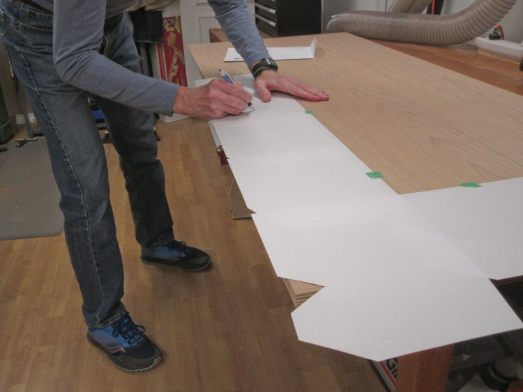
Tracing on the top profile
The shape of the back was printed out on a 1:1 plan. I actually printed only half of it but that took five 8-1/2 x 11 sheets taped together.
Here I'm tracing one of the sides onto the plywood via carbon paper. The plan is actually upside-down for this side which explains the lack of visible lines.
Here I'm tracing one of the sides onto the plywood via carbon paper. The plan is actually upside-down for this side which explains the lack of visible lines.
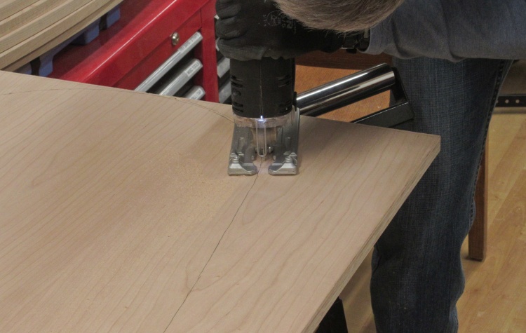
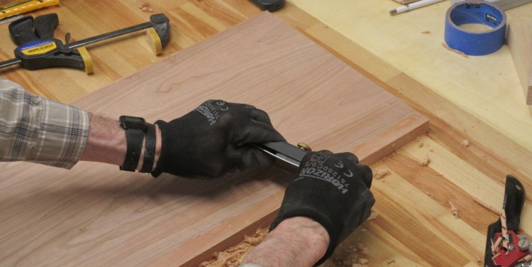
Cutting out the curved parts
The curve was cut out using a jigsaw, which unfortunately leaves a rather splintery top surface. To avoid chips in the veneer, before sawing I used a knife to cut through the plywood veneer near the line to prevent any chips extending across the line.
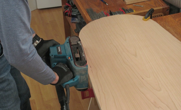
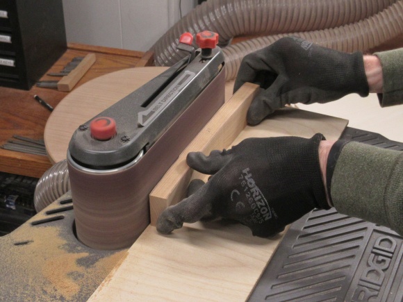
Belt-sanding to the marked line
I didn't cut very close to the line so there was extra wood that needed to be removed. For that I used a belt sander.
I would typically use a bench-top sander for this function but the piece was a bit too large and heavy to manually maneuver onto one of those.
I would typically use a bench-top sander for this function but the piece was a bit too large and heavy to manually maneuver onto one of those.
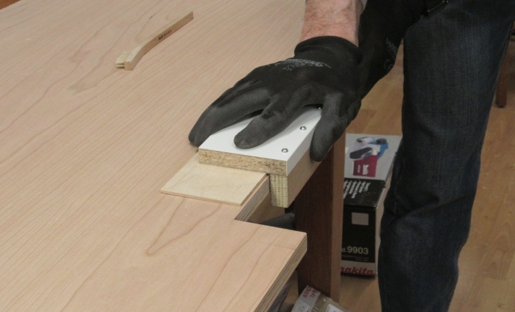
Sanding edges square
The belt sander was fairly effective but it was tough to make the square edge needed for trim application. So I made a sanding jig that let me sand the edge square to the plywood surface.

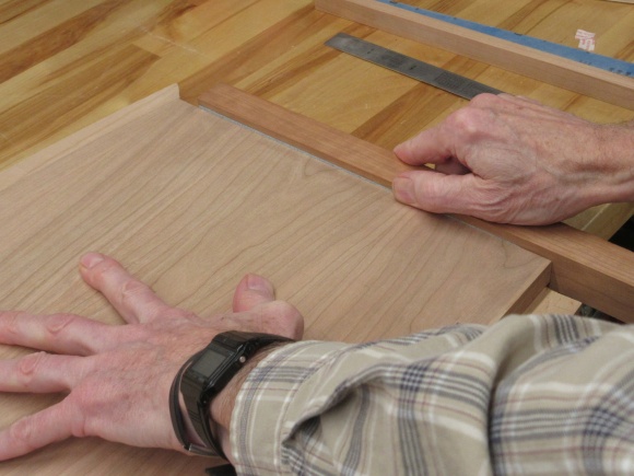
Test-fitting the pieces
I put most of the pieces together for a test-fit and to mark the location of the slots to be cut into the back.
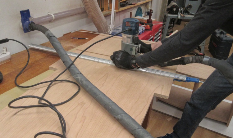
Routing shelf slots in the back
A hand-held router was used to cut the slots.
Almost all flexible vacuum cords have a ridged outside and I wanted to prevent those ridges from rubbing the plywood edge and chipping the veneer, so I wrapped the hose in a thick fabric to eliminate the ridges.
Almost all flexible vacuum cords have a ridged outside and I wanted to prevent those ridges from rubbing the plywood edge and chipping the veneer, so I wrapped the hose in a thick fabric to eliminate the ridges.
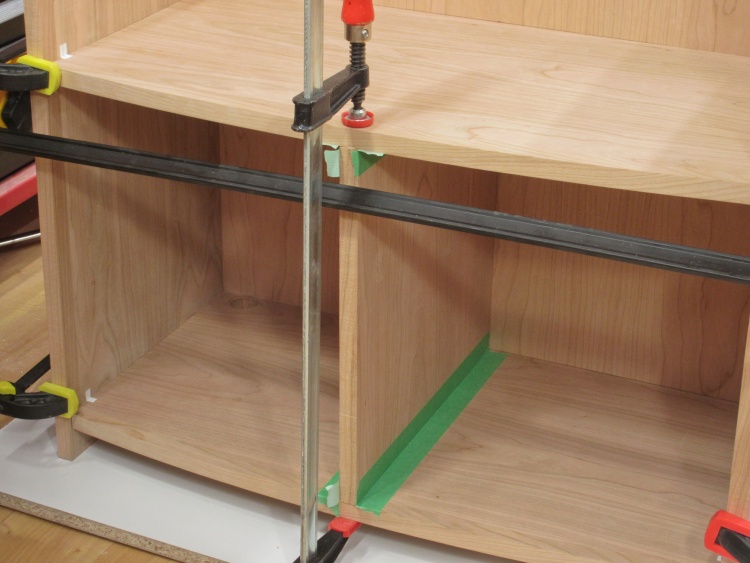
Gluing together the cabinet pieces one at a time
Then after some tweaking to get everything fitting correctly, I glued the cabinet together a step at a time. This shot shows the first step which is gluing in the vertical divider.
Alignment marks to help accurately reassemble the cabinet
I needed to partially disassemble the cabinet between gluing steps so I added alignment marks to the shelves to make sure it would go back together in a repeatable manner.
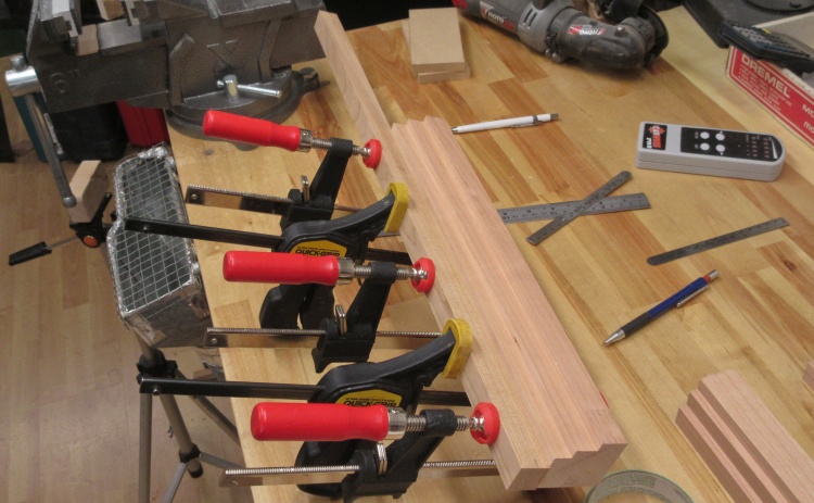
Cutting trim for the back
Three stages of gluing got the lower part of the cabinet together but I needed to do a few things before the back could go on.
Like add the trim to the back. In this shot I'm starting to cut thin (0.13") pieces of trim to cover the top edges.
Like add the trim to the back. In this shot I'm starting to cut thin (0.13") pieces of trim to cover the top edges.
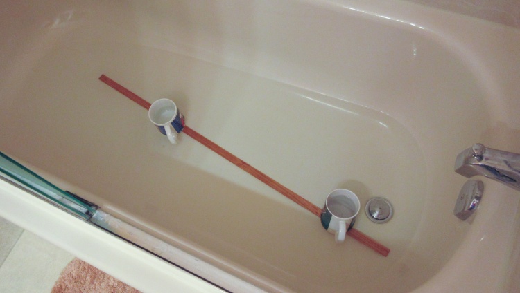
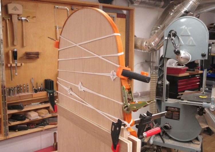
The top piece of trim having a leisurely soak in warm water
I was planning on using three pieces of trim to cover the exposed areas. The center piece wraps around the curved top so to help it make that bend I first soaked it in warm water for an hour or two.
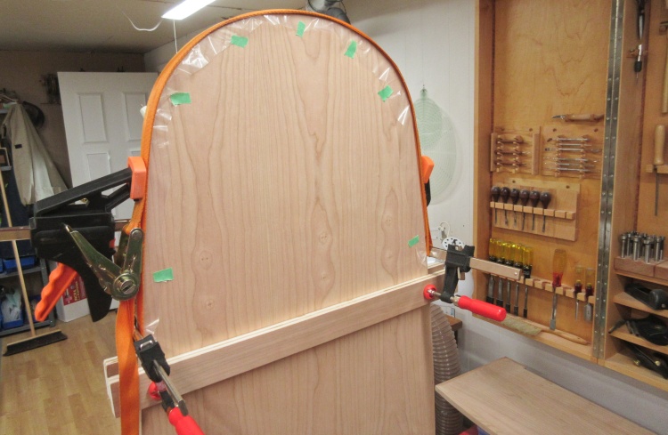
Wet trim piece bent around the back
With a layer of plastic isolating the plywood from the wet trim, I bent it over the top and secured it with a ratchet strap supplemented by a long clamp.
It was left overnight so the trim would have a chance to dry.
It was left overnight so the trim would have a chance to dry.
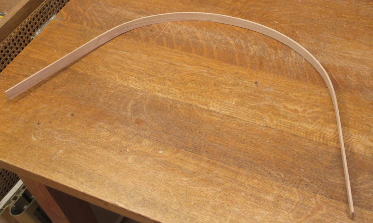
The pre-formed top trim piece after drying
This shows the top trim piece with a nice curve in it and ready for gluing.
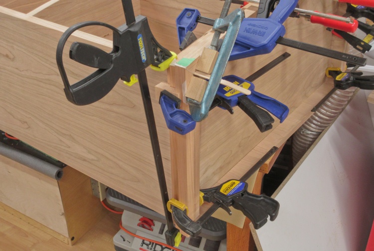
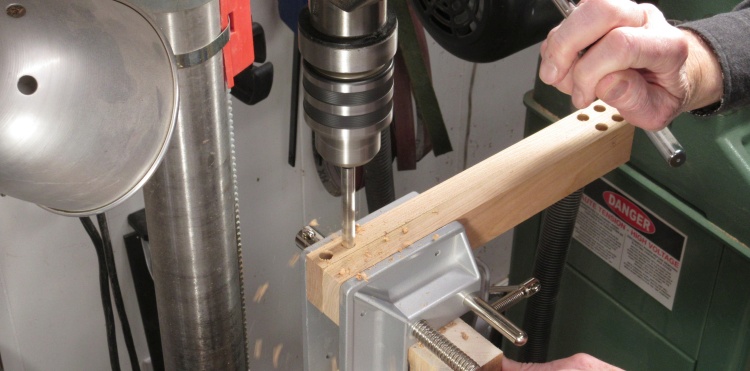
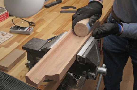
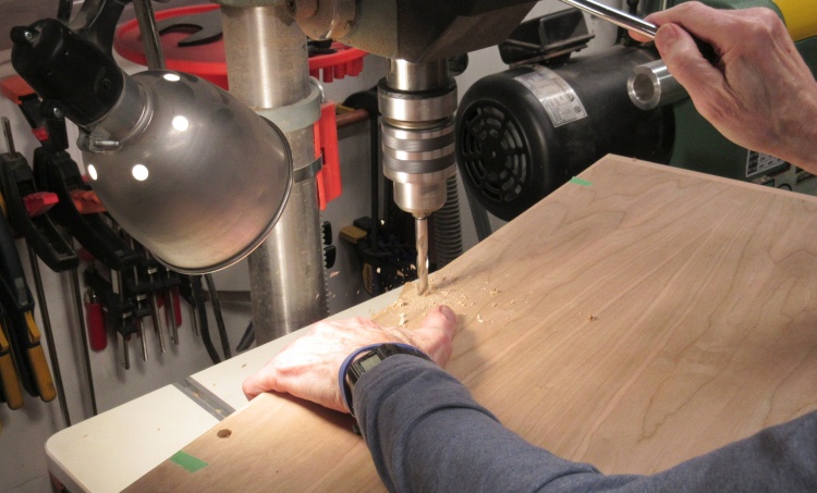
I would need to install the top before the back went on. Since it was quite likely that the cabinet would be lifted using the overhang of the top, it needed to be firmly secured to the rest of the cabinet. I used four 3/8" fluted dowels for that purpose. I first drilled small holes in the dowel locations and installed hole markers (nail ends). Then the top was set in place and pressed down to imprint the hole locations. Finally, 3/8" holes were drilled in the cabinet and top.
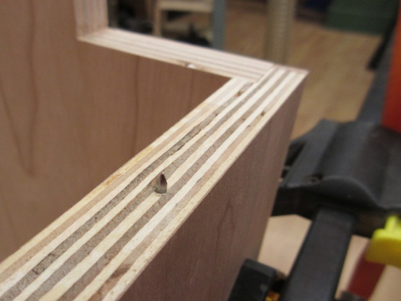
Hole-position-transfer nail
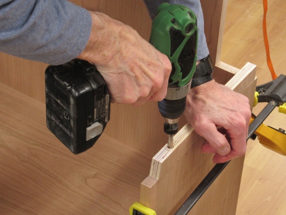
Drilling a dowel hole
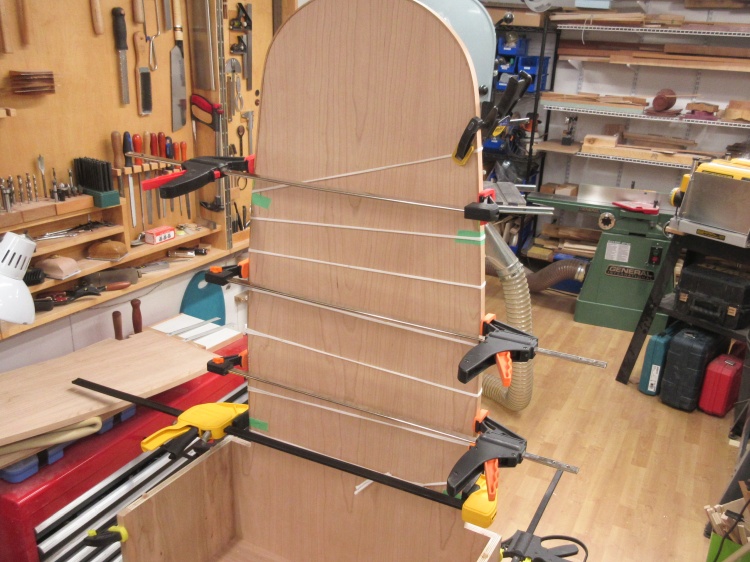
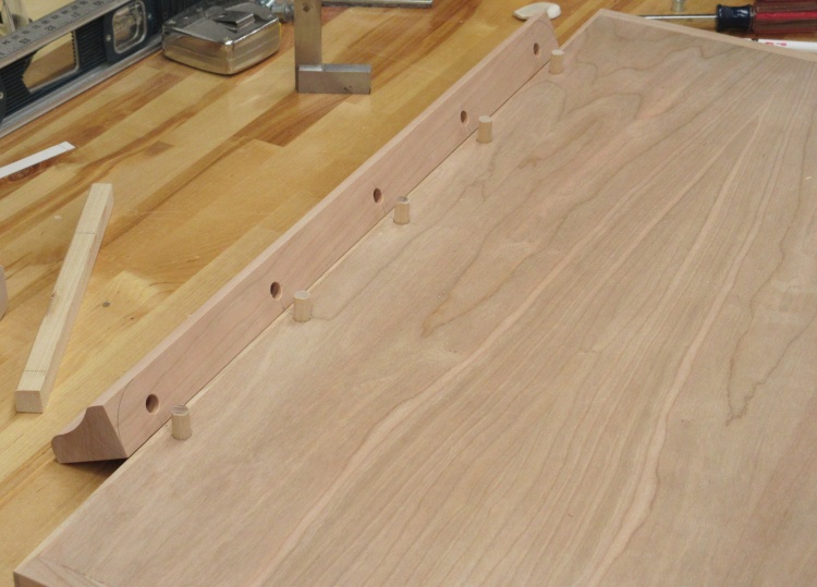
The top trim, glued and clamped
The gluing-on of the top trim was similar to the bending operation but I added the white strapping to apply pressure at a number of locations around the curve.
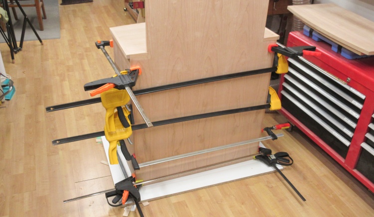
The side trim pieces now glued and clamped
Then the side trim was added. The curve was slight so they could go on without preforming. I used the strapping and clamps to hold things in place while the glue dried.
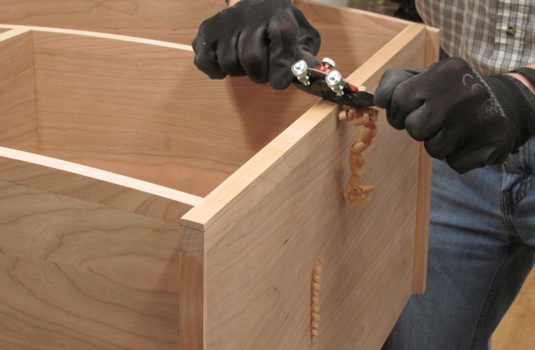
Gluing the back to the carcass
When trim installation was complete, it was smoothed off to be flush with the plywood.
Then the top was glued on and finally the back was glued in place as shown in this shot.
Then the top was glued on and finally the back was glued in place as shown in this shot.
More Carcass
Next ↓ Previous ↑
There was a bit more work to do after the back was installed;
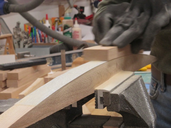
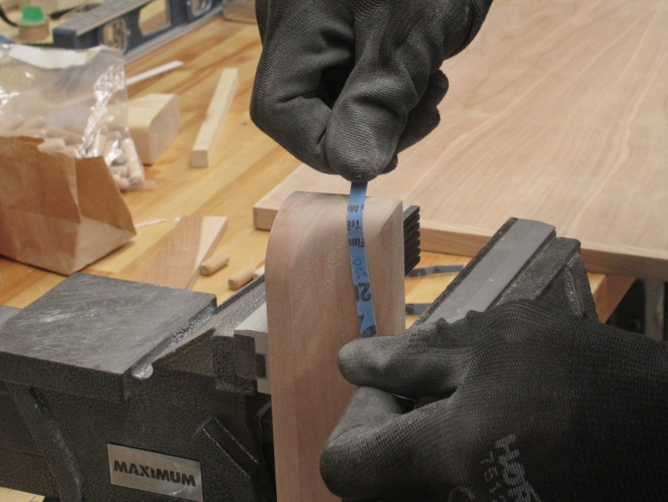
Bevelling the sides to match the shelf curves
The plan was for the front edges of the sides to be contoured to the same curve as the rest of the front. I had left those sides long so then they needed to be cut down to be flush and at the same angle as the ends of the shelves.
I used a spokeshave to do most of the wood removal. That was followed by a block plane for a finer adjustment.
I used a spokeshave to do most of the wood removal. That was followed by a block plane for a finer adjustment.
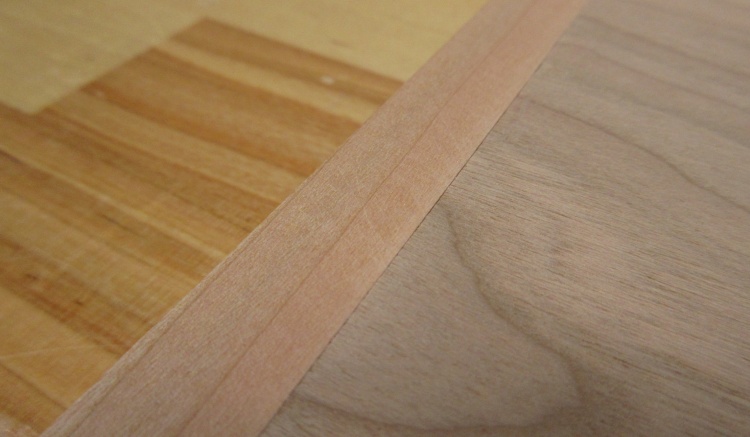
The post-bevelling result
This shows a close and perhaps slightly fuzzy image of the contoured side trim.
Some 2" cherry set up for curved cut
The last big thing for the carcass was the bottom trim.
I'll just totally ignore my first attempt at the curved portion of the trim which failed miserably due to a gluing error. This second attempt was more successful.
It started with yes, once again, the beam compass setup to cut a curved blank for the front trim.
I'll just totally ignore my first attempt at the curved portion of the trim which failed miserably due to a gluing error. This second attempt was more successful.
It started with yes, once again, the beam compass setup to cut a curved blank for the front trim.
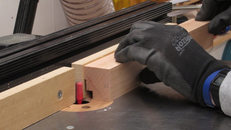
Routing the profile
A one-inch-wide piece was cut for the trim but then I (temporarily) glued it back on the main piece to make it more stable for routing.
The finished trim shape has three steps as shown by the pencil lines on the end. Note that the trim is upside-down for the routing operation.
The finished trim shape has three steps as shown by the pencil lines on the end. Note that the trim is upside-down for the routing operation.
Straight side pieces routed the same way
I cut a straight piece of cherry to be used for the two side trim pieces and here I'm finishing off the routing.
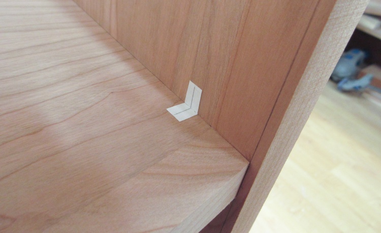
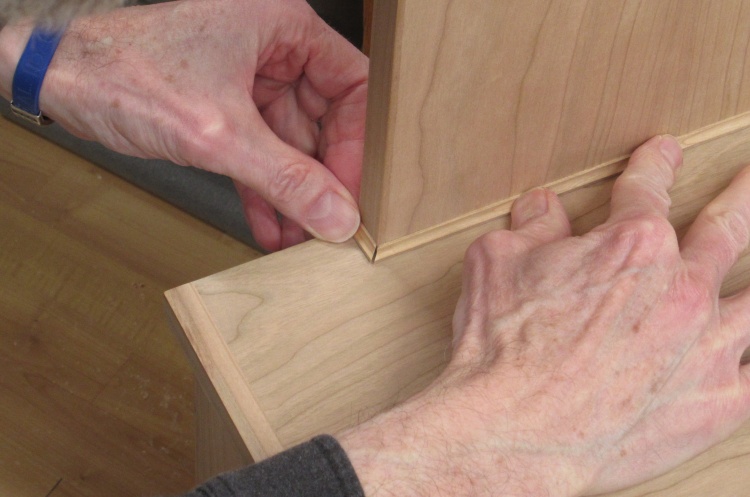
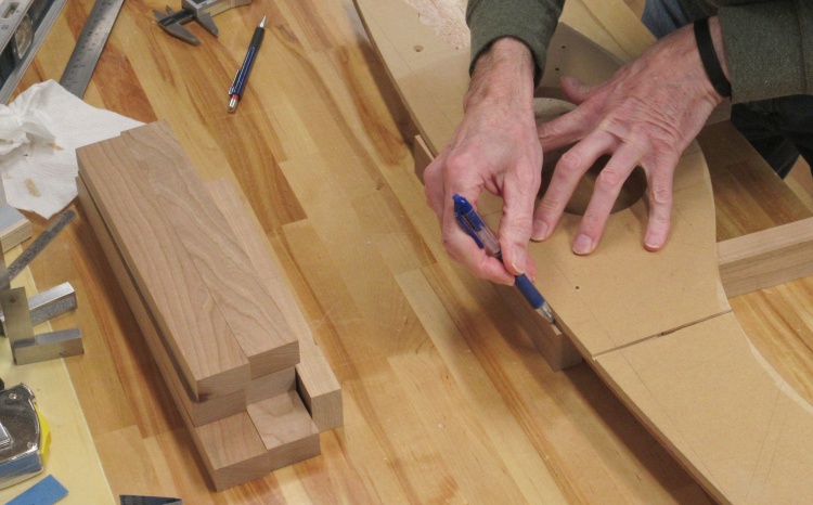
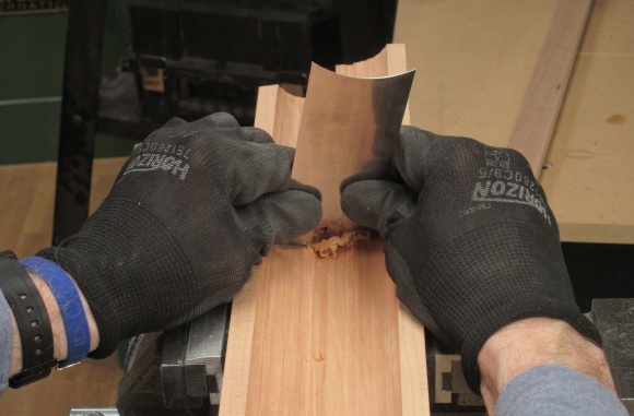
The front trim would butt up against the front of the bottom shelf but I thought it would be difficult to match the curves well enough that there would be no visible gaps. My solution was to have the trim inset into the front of the shelf. That would mean the shelf/trim interface was flat, plus then any gap is horizontal and therefore less visible.
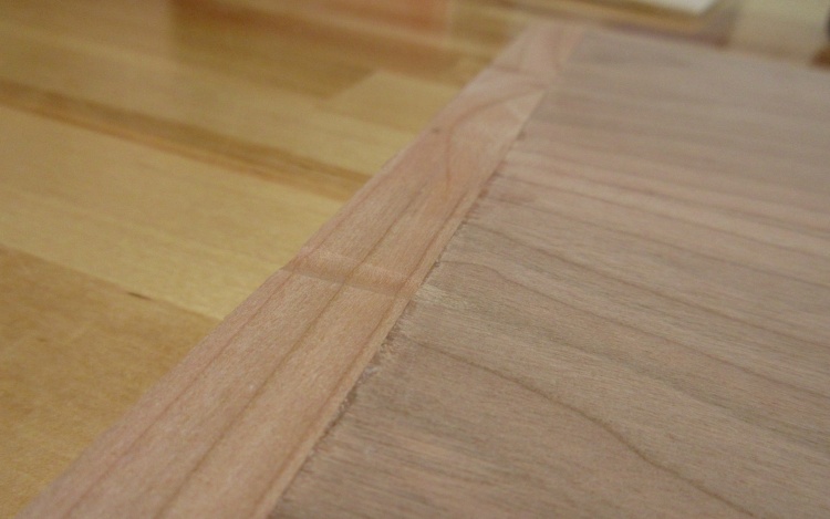
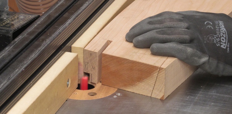
Since I cleverly neglected to route the front of the shelf before it got assembled into the cabinet, I was going to need to notch the bottom part manually. I started by scoring the wood along the edge of the trim and then cutting out a 1/8"-deep notch under that line to the bottom.
Since I cleverly neglected to route the front of the shelf before it got assembled into the cabinet, I was going to need to notch the bottom part manually. I started by scoring the wood along the edge of the trim and then cutting out a 1/8"-deep notch under that line to the bottom.
Scoring shelf at trim edge
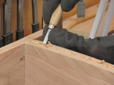
Cutting out lower edge of shelf
Mini-router helps remove wood
Smoothing the round trim edge
The trim pieces would join on the corners with not-quite-45° miters. After carefully measuring and marking I cut the miter a bit long on the curved front piece and then used the disc sander to flatten the face.

Sanding the side trim wire notch
The side pieces got the same miter treatment. In addition the left trim needed a notch to accommodate the AC wire going into the cabinet.
Gluing the bottom trim
After many tweaks and miter checks, I finally glued the trim pieces on. I did this piece by piece so there would be enough time to ensure everything was perfectly positioned. This shot shows the left-side trim being glued.
Despite my conscientious care with the miters, they still ended up crappy and gappy. Since everything was glued in place all I could do was patch them. The first shot shows the type of thin wedges used to fill the gaps, in this case a couple on the top edges of the trim. The second shot shows the joint after all the gap filling was finished. It actually looks pretty respectable, especially if you don't look too closely.
A sadly typical gappy miter
Better-looking after some TLC
Adding a small molding to the back
Lastly I routed a small molding that would hide the joint between the back and the cabinet top.
Here I'm checking the fit of a couple of the pieces.
Here I'm checking the fit of a couple of the pieces.
Door Frames
Next ↓ Previous ↑

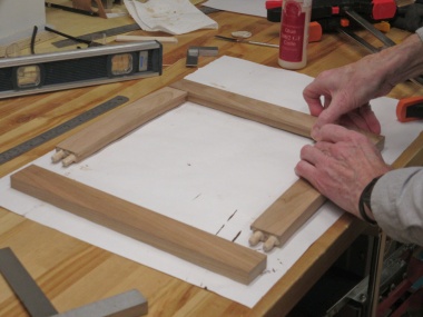
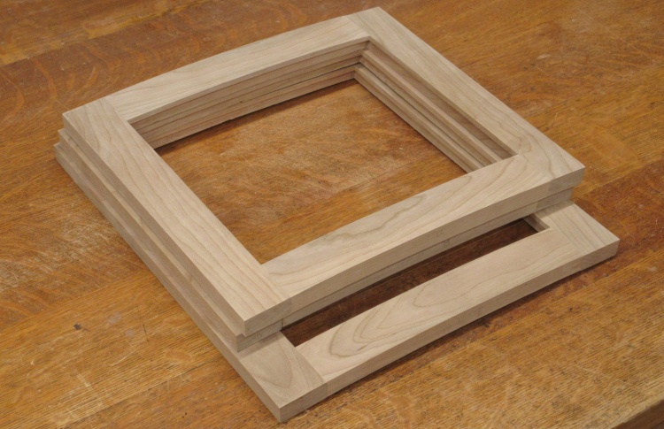
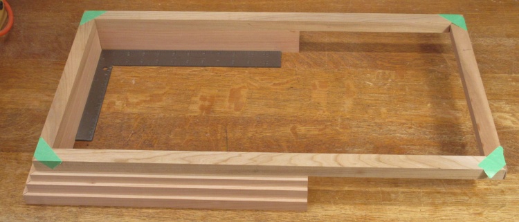
The frame bits are dowelled together
The cabinet doors use a conventional frame-and-panel construction held together with splined dowels.
The only complicating factor is that the doors need to be curved to match the profile of the cabinet front.
The only complicating factor is that the doors need to be curved to match the profile of the cabinet front.
Starting to chop up a new plank of cherry
I got to work cutting up a new plank of cherry to make the dozen pieces required for the three door frames.
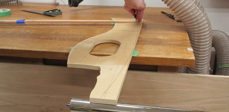
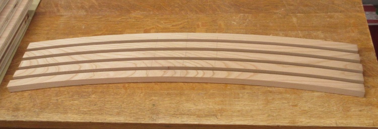
Marking curve on door pieces
The usual sawing/jointing/planing ensued resulting in the small pile of frame pieces as can be seen here.
In this shot I've dug out the curve pattern I made about 75 photos ago and I'm marking the curved profile onto the top and bottom frame pieces.
In this shot I've dug out the curve pattern I made about 75 photos ago and I'm marking the curved profile onto the top and bottom frame pieces.
The six top and bottom pieces marked
These have all been marked with the curved profile and the properly-angled ends.
I cut the ends first so the still-rectangular pieces would provide a nice flat reference surface from which to cut the appropriate angle (3.6°). It always takes several iterations to set up the radial arm saw to get an accurate cut angle so instead I just used the bandsaw followed by the disc sander to flatten the surface.
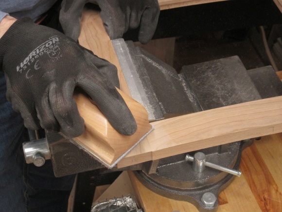
Cutting an end at the proper angle
Flattening the end
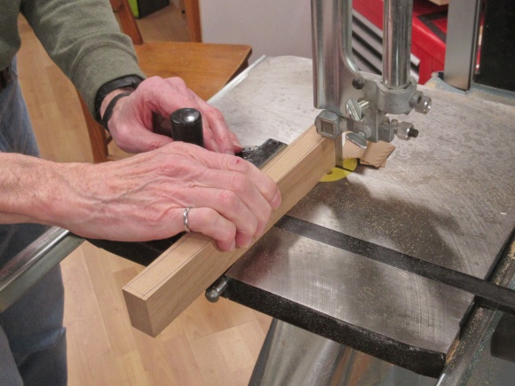
For the shorter curves of the door pieces, rather than use the beam compass setup again I just cut them on the bandsaw close to the marked lines and then smoothed the curves using the oscillating belt sander.
Cutting the curve
Smoothing the outside curve
Curves sanded using a machine typically need to be touched up if a really smooth surface is needed. I thought I'd do that so I reused various cutoffs and jigs to make convex and concave sanding forms and sanded both sides of the curved pieces until they were even.
Adjusting the inside curve
Adjusting the outside curve
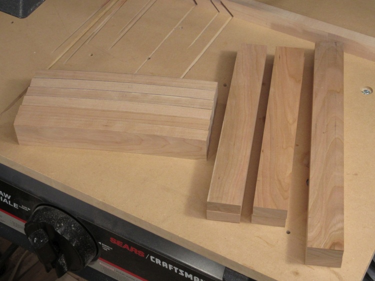
The 12 door pieces to be assembled
This is the collection of door pieces ready for the next chapter in their woody stories; getting made into door frames.
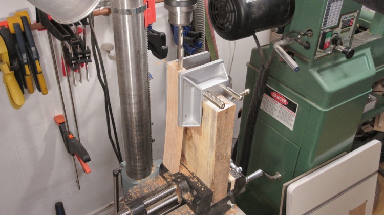
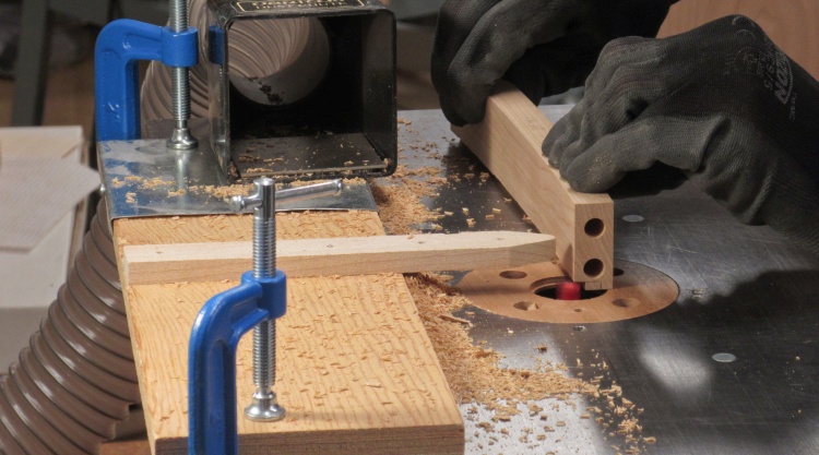
Drilling dowel holes in curved rails
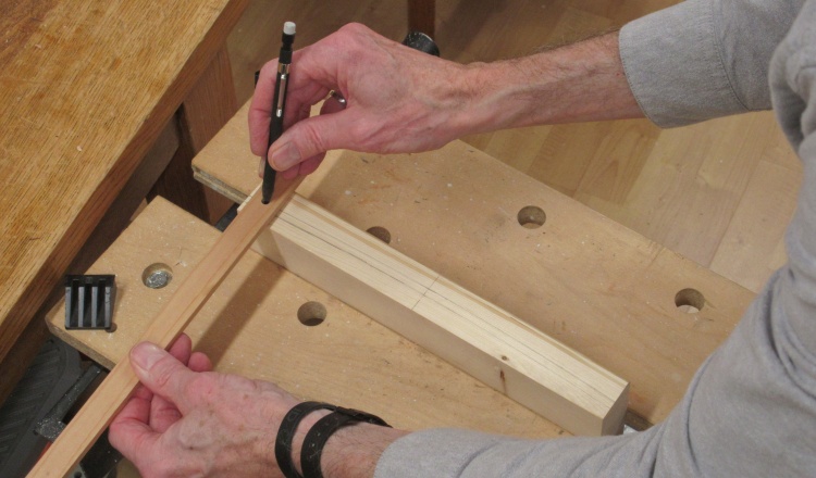
The plan was to use 3/8" splined dowels to hold the frame together. I set up the drill press to be able to drill into the frame ends and then started by drilling 3/8" holes in the ends of the curved top and bottom frame pieces.
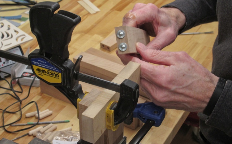
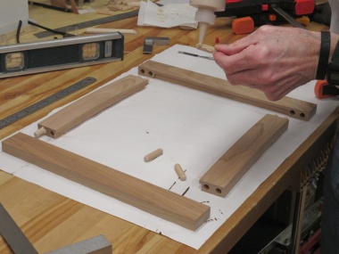
Dowel position markers in place
I had previously used nails to transfer hole positions but that requires a couple extra steps.
This time I used dowel center markers that fit right into the 3/8" holes. When pressed against the mating board they leave indents to indicate drill positions.
This time I used dowel center markers that fit right into the 3/8" holes. When pressed against the mating board they leave indents to indicate drill positions.
Drilling matching holes in straight rails
Then the straight frame pieces were drilled exactly in the marked locations.
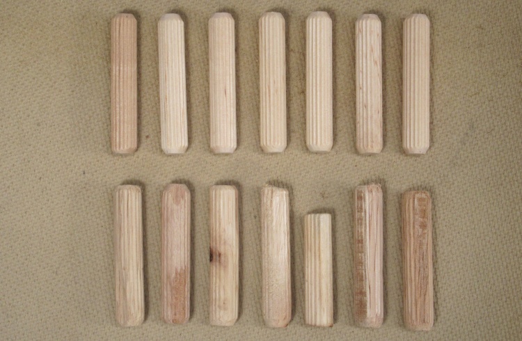
Good and bad fluted dowels
I wasn't going to have enough fluted dowels for all the doors so I picked up a package at Home Depot - the lower row in this photo. The bag said they were spiral dowels but in fact they were fluted although that wasn't actually a problem.
What was a problem was they they were not even round and they were mostly too large to fit into a properly-sized hole. Plus they were of egregiously poor quality with varying lengths, diameters and straightness.
I fired those into the garbage and made a pilgrimage to the remote North (well, Lawson Heights Mall) to pick up a pack of decent ones from the reliable Lee Valley Tools.
Routing notch on inside of rails
The last bit of prep was to route a slot to hold the panel.
Then the frames were assembled; glue applied, pieces assembled and then clamped.
Applying glue to dowels
Assembling the frame
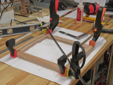
Clamped while drying
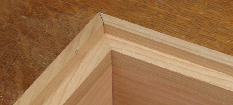
Once the glue was dry there was a bit more work to do, including squaring up the notches in the back and sanding the corners flush.
Making the notches align nicely
Making the corners flush
The three frames
That was it for the frame construction.
They would still need to be trimmed to size (they were made about 1/16" large on each side) and have the hinge mortises cut.
They would still need to be trimmed to size (they were made about 1/16" large on each side) and have the hinge mortises cut.
Door Panels
Next ↓ Previous ↑
The door panels would need to be fairly thin pieces of wood with a slight curve that matched the rest of the cabinet front. Since the piercing would leave lots of narrow sections of material, I'd need to use plywood to have enough strength in all directions to prevent breakage.
I thought I'd better do a test run since I wanted to try out a few things; making the Aspen plywood in a curved shape, trying out some cutting and sanding techniques, and making sure the pattern looked reasonable.
I thought I'd better do a test run since I wanted to try out a few things; making the Aspen plywood in a curved shape, trying out some cutting and sanding techniques, and making sure the pattern looked reasonable.
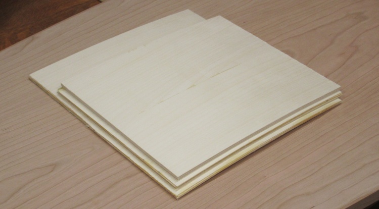
Test Panel
I decided to use a 5-layer plywood with each ply being about 0.04" for a total thickness close to 0.2". After the usual rigamarole of changing to a new resaw blade on the bandsaw and finding the best way to saw thin sections for the specific wood I was using, I managed to cut five slices for the plys. They were each jointed smooth on one side before cutting and were cut about twice as thick as needed since imperfect settings/cutting/wood grain/karma results in some sections thinner than the nominal thickness.
Then the layers were run through the drum sander multiple times to get them to a consistent 0.04" thickness. We've now caught up with the laggardly photo-taking which starts with the lamination process.
Then the layers were run through the drum sander multiple times to get them to a consistent 0.04" thickness. We've now caught up with the laggardly photo-taking which starts with the lamination process.
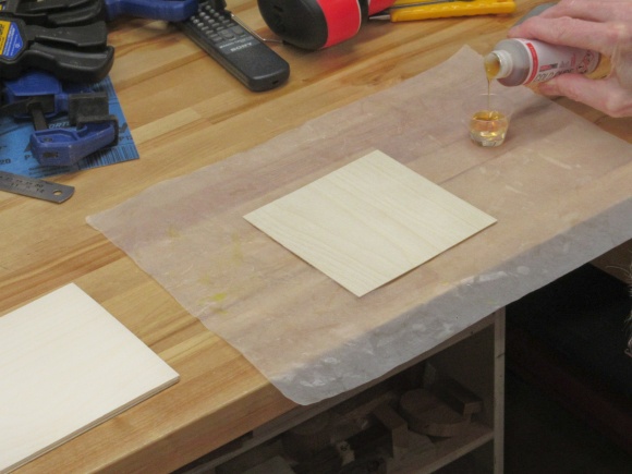
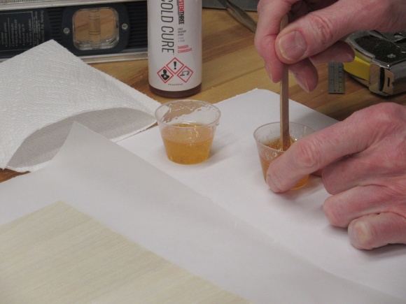
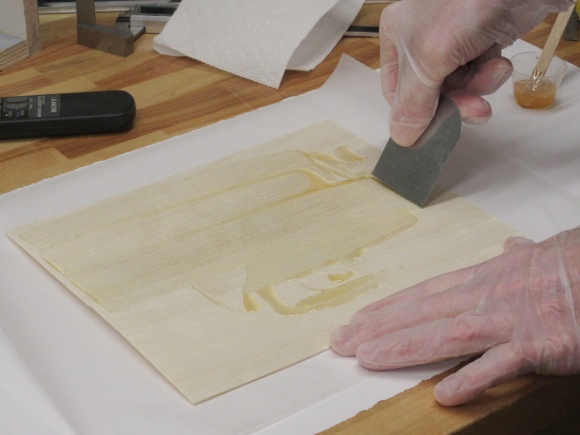
Adding the hardener

Mixing up the epoxy
I used my Cold-Cure epoxy which has a low viscosity and more importantly a long open time to prevent "glue panic". If I'd used 5 minute epoxy the 5 plys would probably in fact have to be glued in two stages which would be as they used to say in ancient Rome "dolorem in asinum". Of course the grain orientation was alternated between adjacent layers of the aspen and four applications of epoxy completed the 5-ply stack.
Spreading glue on the first ply
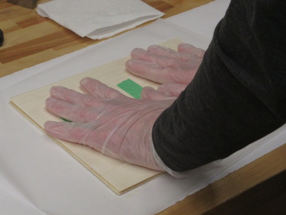
All five plys glued together
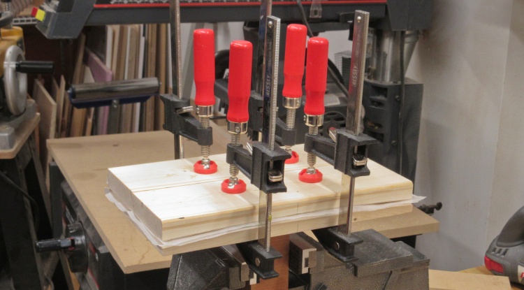
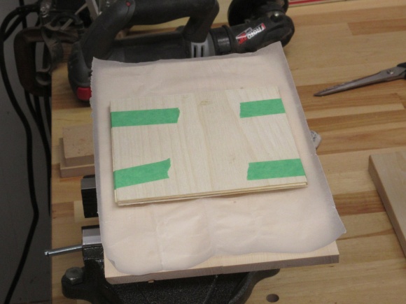
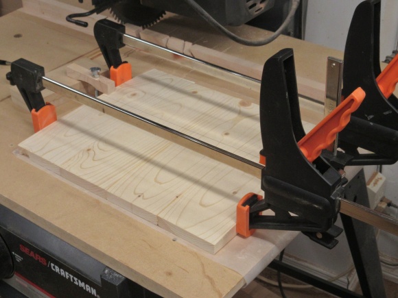
Clamping in curved form
Way back up at the top of this page I'd made a curved form out of 2x4s. It sat around until this test panel was assembled and then the panel with fresh glue went between the two halves of the form and got clamped tightly and left overnight.
Layers of wax paper prevented the form from sticking to the somewhat gluey panel.
Layers of wax paper prevented the form from sticking to the somewhat gluey panel.
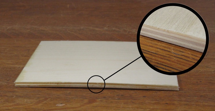
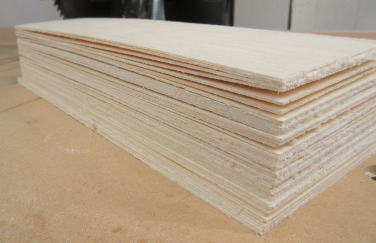
Nicely curved piece with the plys shown
The curve of the form had been made to match that of the cabinet although I thought it might need to be a bit tighter to accommodate some relaxation of the panel. But it turned out just fine - the panel ended up the correct curve and monitoring over a few weeks showed the curve was stable as well.
The magnified section reveals the five plies (after some edge sanding).
The magnified section reveals the five plies (after some edge sanding).
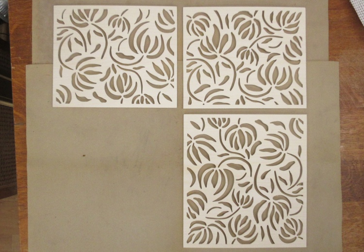
Pattern
Before the next section I should mention the incised pattern that helps define the look of the cabinet. I didn't have a specific pattern in mind when I started although I had seen a photo of a cabinet with an incised floral pattern that helped inspire this approach.
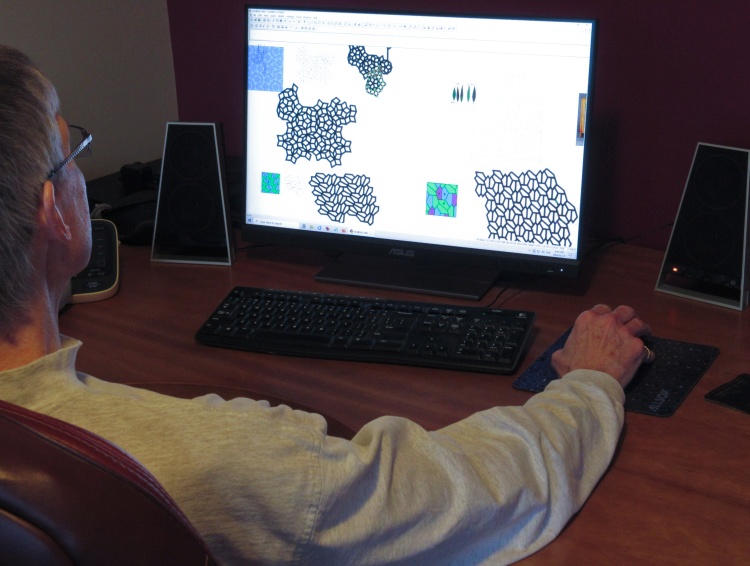
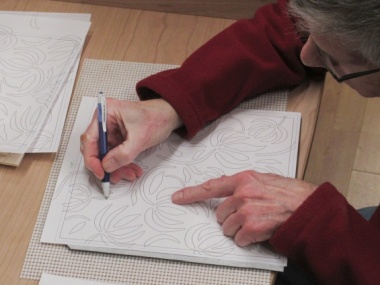
Looking at some rejected designs
One option would have been to copy the floral design on the cabinet I'd seen but I wanted to avoid that if possible.
Furthermore I didn't want too much "hole" and the remaining wood had to be thick enough for decent strength and I didn't want to cut a million holes and of course I had to like the design.
I did a fair amount ofagonizing considered cogitation over possible designs and sketched up a number of them before my dissatisfaction with them led me to look for ideas yet again. Eventually I came across the Matisse paper cut.
Furthermore I didn't want too much "hole" and the remaining wood had to be thick enough for decent strength and I didn't want to cut a million holes and of course I had to like the design.
I did a fair amount of

The original Papier Dècoupè art used
Reportedly Matisse worked almost exclusively in Papier Dècoupè the last decade of his life. It consisted of painting sheets of paper to colour them and then cutting out designs and arranging them to make the artwork. It sounds a bit like a grade 2 art project to me but if you are an senior influential 20th century impressionist I suppose even that gets respect ("Consideration of the works by exploring a host of technical and conceptual issues: the artist’s methods and materials and the role and function of the works in his practice; their environmental aspects; their sculptural and temporal presence as their painted surfaces exhibited texture and materiality..."). Gotta love curator-speak.
Matisse had many paper cuts based on various leaf shapes but this particular flower-like design seems unique among his works.
Matisse had many paper cuts based on various leaf shapes but this particular flower-like design seems unique among his works.
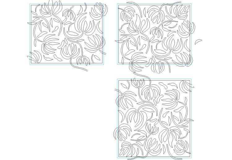
The resulting designs for the three doors
I used the general flower shapes (minus some of the more random bits) and extended the technique to provide a larger area of coverage.
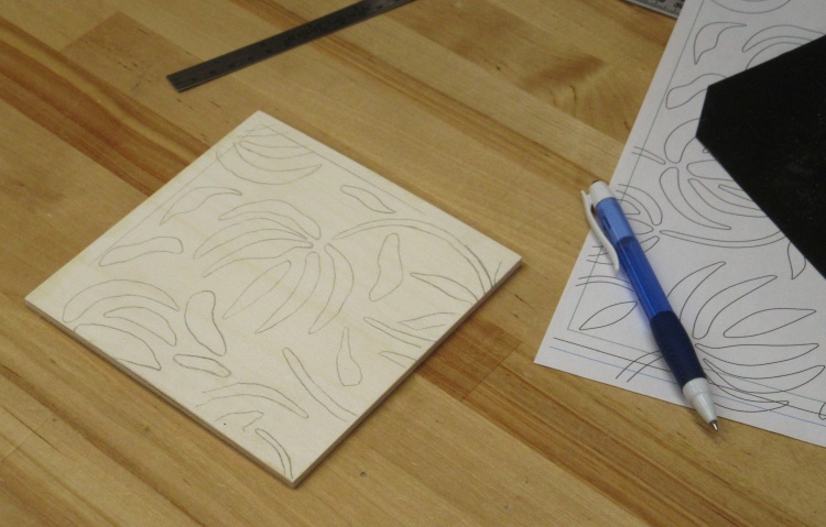
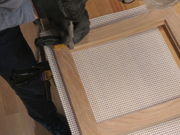
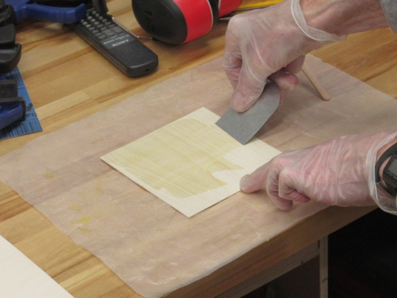
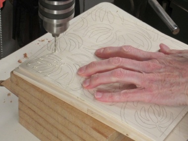
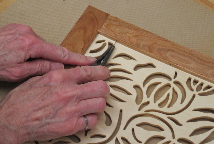
A section of the pattern copied onto the test piece
Next up was checking the cutting-out of the design. I started by tracing onto the plywood a section of the pattern I planned to use.
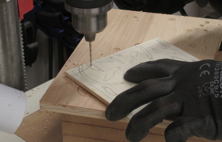
Drilling starting holes
In each opening-to-be I drilled a couple holes that would let me insert the saw blade.
Using a mini-jigsaw to cut out shapes
I had a new mini-jigsaw to try out so I, well, tried it out.
It worked reasonably well except it was a bit tough to keep the blade in sight especially since it accumulated sawdust quickly. It wasn't a very ergonomic design due to the size so that didn't help either. However it seemed the cut the soft Aspen adequately.
It worked reasonably well except it was a bit tough to keep the blade in sight especially since it accumulated sawdust quickly. It wasn't a very ergonomic design due to the size so that didn't help either. However it seemed the cut the soft Aspen adequately.
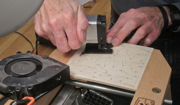
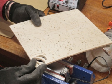
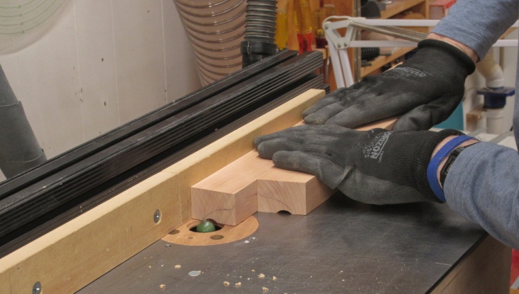
A more-ergonomic sawing setup
It turned out to work much better with the jigsaw mounted upside-down in a vice with the panel being moved manually around the blade to make the cuts as seen here.
That had a number of advantages:
- I didn't need to try to hold the silly little saw body (while pressing the underside trigger);
- It provided a clear view of the blade and made it easier to blow away the sawdust;
- It eliminated the rather awkward clamping of the panel, and;
- The clean side of the cut was on top, leaving the bottom with the slightly chipped edges.
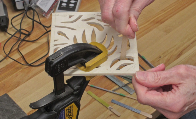
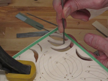
Sanding the holes
The edges of the openings were sanded with a selection of sanding sticks and files to smooth out the curves.
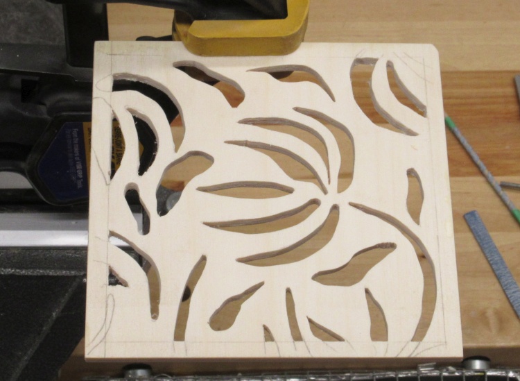
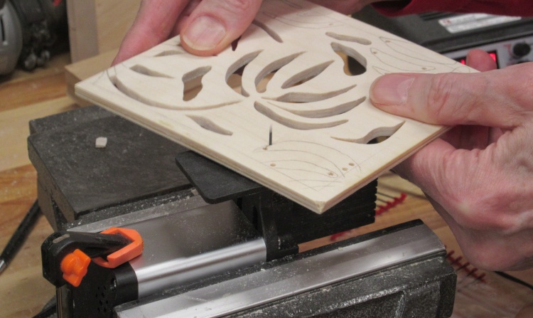
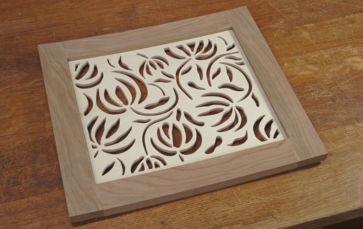
The completed test piece
I didn't bother finishing all the sanding but I decided that the resulting effect was about what I was looking for.
There were no problems with the process I had settled on so there was nothing stopping me from tackling the real panels.
There were no problems with the process I had settled on so there was nothing stopping me from tackling the real panels.
The Real Panels
I'd need three panels for the cabinet but they would all go together the same way as the test panel. I started by cutting up the aspen into the proper lengths. I wanted to minimize the width of the wood pieces since the accuracy of cutting the slices drops with increasing widths. I ended up making them half the height of the panels which would result in a single seam on the outside layers.
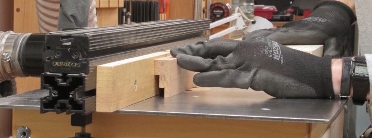
Starting to cut up the Aspen plank
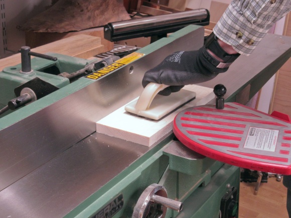
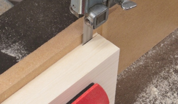
The face gets jointed flat before each slice
Of course the band saw was used to cut slices off the planks. First I'd joint the face I was going to cut off so it was flat and smooth and then take the slice off as seen below. Then I'd joint the newly cut face on the plank, take another slice and repeat. The nominal slice thickness was about 0.08" but that needed to be reduced down to 0.04" which was achieved by running them through the drum sander repeatedly. I used 120 grit on the drum and tried to take no more than about 0.006" per pass.
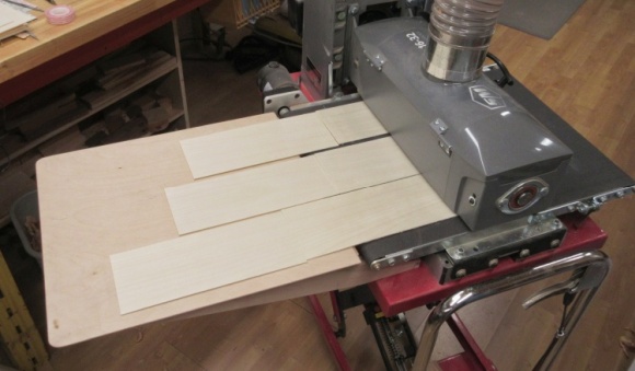
A pile of plies ready to go
This is the complete set of post-sanding pieces, now a consistent 0.04" thick. The edges are still a bit fuzzy but I'll clean those up later with a sanding block.
Re-making a Jig
Unfortunately the curved plywood press I had used for the test panel wasn't going to be large enough for the door panels. Rather than try to extend that one I just grabbed some more 2x4 stock and made one that was big enough. Four pieces were cut to length and then I set up the beam-compass jig once again to cut the curve into them.
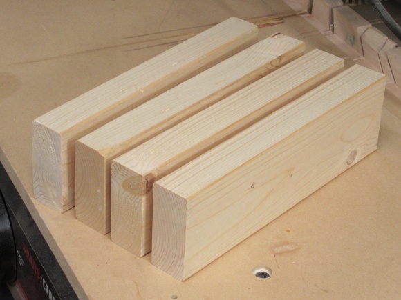
A fresh batch of 2x4 pieces
Cutting to the requisite 81"-radius curve
The four convex pieces were glued together to make one side of a press large enough for the 9x11" panel, and then the same was done with the concave pieces for the complementary side. After the glue dried I did a bit of sanding to remove high spots.
Laminating together for a panel-sized form
A bit of sanding to remove high points
Doing the glue-up
The gluing process was similar to that for the test panel. I mixed up enough epoxy for a 0.001" adhesive thickness (using two containers since it was too much for one). I then used my sheet-metal spreader which has tiny notches in the edge to make lines of adhesive.
Mixing up the epoxy
Spreading epoxy on an outside layer
Of course once again the grain orientation of the layers was alternated as the five layers were built up. The two half-sized pieces forming each of the outside plies were taped together to help ensure a tight seam. Once the last layer was in place, the stack went into the form and was thoroughly clamped.
Adding the last of five layers
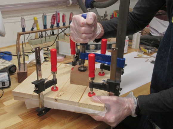
Tightening down the curved form
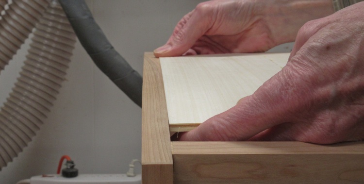
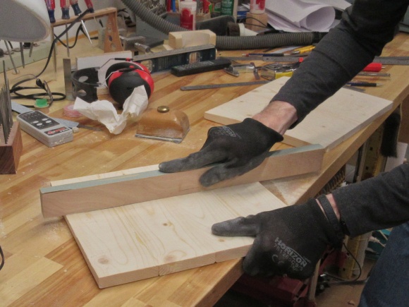
Panel curve seem to match the cabinet curve
After the panel glue was set, I trimmed an edge and compared the curve to that of the cabinet - it looked pretty close (note that the cabinet is laying on its back in this photo).
The three panels ready for trimming
The three panels awaiting the next stage in their evolution.
I used my standard 1:1-plan-and-carbon-paper technique to trace the pattern for each panel onto the outside faces, then drilled starting holes and finally started to cut out the shapes. This setup uses the same upside-down mini jig saw arrangement that was used for the test panel.
Tracing on the pattern
Drilling some starting holes
Starting to cut out the shapes
My practise was to cut a group of holes and then sand those before starting on the next group. The sanding evened out the not-necessarily-smooth sawn edges of the holes and cleaned up the ends. The following photos showed some of the edge-smoothing variety of tools I used.
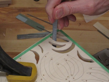
Curved sandpaper
Needle file

Abrasive "dressing" tool
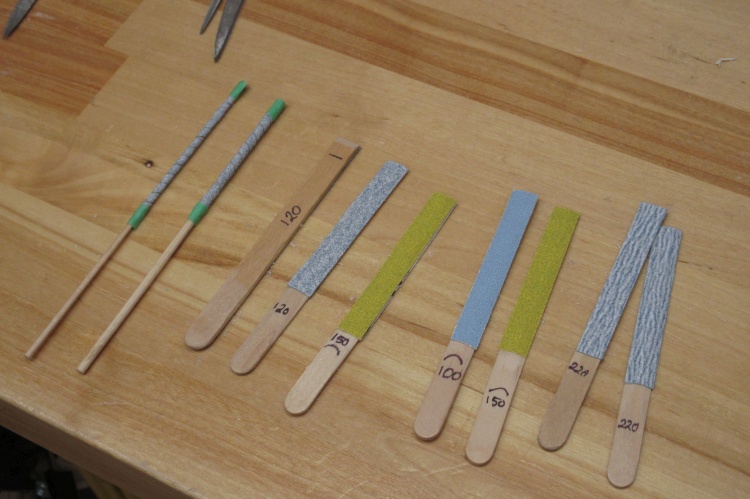
Fresh sandpaper added to sanding sticks
Between panels I replaced the sandpaper on the mostly-popsicle-stick sanding jigs I used. The sandpaper was cut to size for each stick and then held on with double-sided tape.
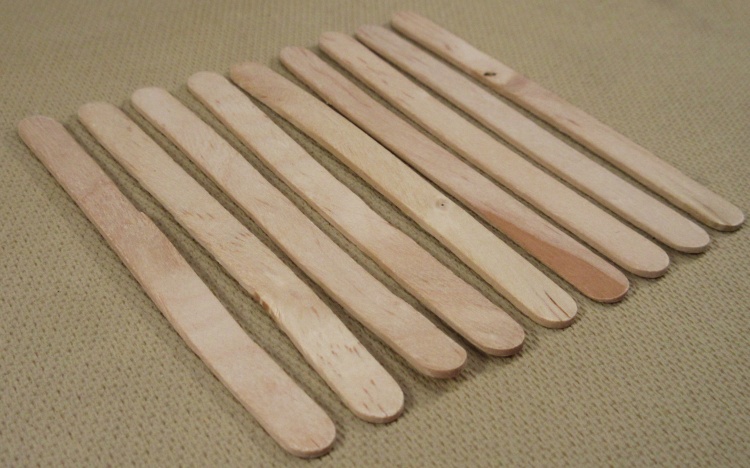
A pathetic selection of popsicle sticks
I ran out of popsicle sticks for sanding jigs so I picked up a bag at a conveniently-located dollar store. Mistake. The photo shows a selection from the bag. Almost every one was, not to put too fine a point on it, crap.
Of the 100 sticks there were maybe 10 decent ones and even those were a bit warped. Apparently one must be vigilant when buying cheap wood things.
Of the 100 sticks there were maybe 10 decent ones and even those were a bit warped. Apparently one must be vigilant when buying cheap wood things.

Cleaning up the top side of the first panel
Once each panel was completed, the top surface was sanded to smooth rough edges and remove any remaining pattern marks.
The three panels completed
I beavered away on the panels and after about a week the three were completed.
Mounting the Shelves
Next ↓ Previous ↑
I wanted to avoid the framing that a conventional shelf construction would use so that meant the shelves would need to be cantilevered, i.e. supported from only one end. It would be prudent to see if that was going to be strong enough so I rummaged around deep in the dusty areas of my cerebral cortex for information from a Statics class taken back in the early eighties.
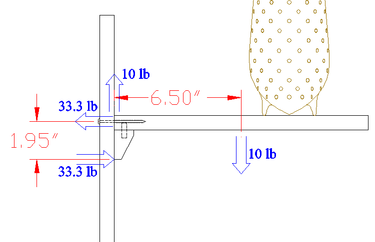
The relevant forces
If the shelf is to be static i.e. not moving, then the forces - both linear and torque - must be balanced.
The weight of the shelf plus about half the turnings I had stored on the filing cabinet were less than 10 lb. At 10 lb that needed 33 lb pulling on the screws and pushing on the support to counter the torque. That should be no problem with even double the weight.
The weight of the shelf plus about half the turnings I had stored on the filing cabinet were less than 10 lb. At 10 lb that needed 33 lb pulling on the screws and pushing on the support to counter the torque. That should be no problem with even double the weight.
Shaping supports
My simple analysis above assumes the shelf and support are one rigid assembly, so I needed to (as Jean-Luc Picard would say) "make it so". To that end I used a fairly wide support at 1.25" but tapered it to keep it from looking too blocky.
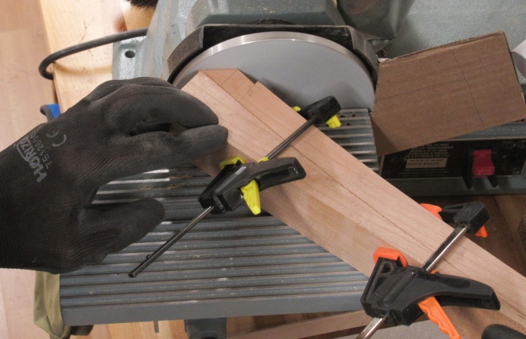
I taped the two supports together bottom-to-bottom to make a single piece for shaping. That way I could just flip the assembly end-for-end to shape both pieces with the same router setting.
I taped the two supports together bottom-to-bottom to make a single piece for shaping. That way I could just flip the assembly end-for-end to shape both pieces with the same router setting.
The resulting curves were a series of little arcs cut by the router bit so I needed to transform that into smooth curves. I started with a curved scraper to remove most of the bumpiness and then switched to coarse sandpaper on a large round form to finish the smoothing.
Scraping off major bumps
Sanding smooth
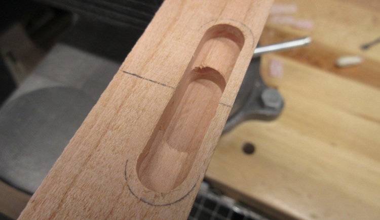
Drilling pin holes in shelf bottom
I didn't think just gluing the support to the shelf would necessarily be adequate since that would put all the force through the veneer layer of the plywood. So in addition to glue I would use five 3/8" dowel pins to transfer forces directly to the body of the plywood.
Here I'm drilling the pin holes in the shelf.
Here I'm drilling the pin holes in the shelf.
Shelf, support & pins
This shows the support with shelf and pins. I just need to finish the ends of the supports before joining everything.
Rounding the ends of the supports
The support ends were cut at an angle and then belt-sanded into a reasonable curve. In this shot I'm finishing up the sanding with finer-grit strips of sandpaper.
Gluing on a support
And then it all went together with glue and a plurality of clamps.
Once the glue was dry I jointed the rear edge (including the support) to give the shelf about 0.5° of upward slope to compensate for any slight sag it may be subject to.
Once the glue was dry I jointed the rear edge (including the support) to give the shelf about 0.5° of upward slope to compensate for any slight sag it may be subject to.
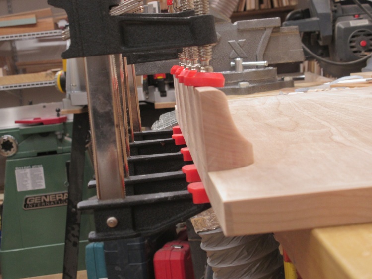
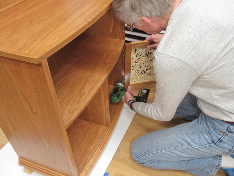
Mounting the top shelf
I used 3-1/2" structural screws for the shelves since:
a. They had nice wide heads and
b. I happened to have a box on hand.
a. They had nice wide heads and
b. I happened to have a box on hand.
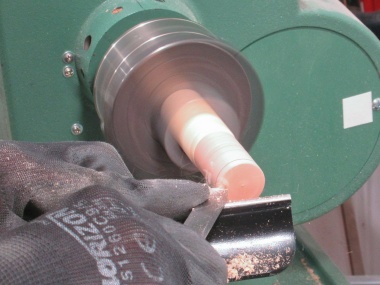
Blank for caps mounted on lathe
The screw heads in the above photo are on the back and would be against a wall so they shouldn't actually be visible. However they still looked pretty ugly so I decided to make some caps to conceal the ugliness.
I laminated together a few layers of cherry to make face-grained caps and glued those to a dowel so I could mount it in the lathe. I suppose I could have just used a thick piece of cherry but I had lots of scraps to get rid of.
I laminated together a few layers of cherry to make face-grained caps and glued those to a dowel so I could mount it in the lathe. I suppose I could have just used a thick piece of cherry but I had lots of scraps to get rid of.
I marked the desired thickness from the end which was then rounded with a scraper. That shaped section was cut off using a small saw as the lathe turned slowly and then I repeated the mark/shape/cut process for the next one. Once I had enough (8) and some spares (6) they were placed in a contoured holder jig and sanded to a more-accurate thickness. Then the flat bottom was hollowed using an abrasive bit in the Dremel to provide clearance for the screw heads.
Once done, these were set aside since they would not go in place until after the shelf was finished and assembled.
Once done, these were set aside since they would not go in place until after the shelf was finished and assembled.
Shaping a cap
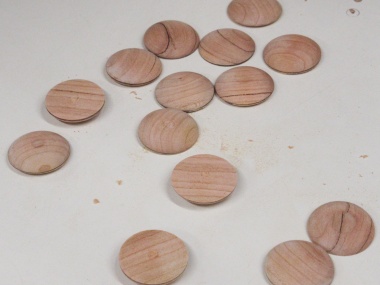
A collection of raw caps
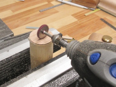
Making a hollow for screw head
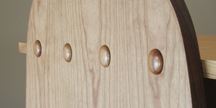
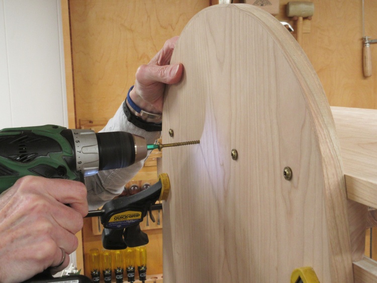
Eventually the back will look like this
Now we'll cheat and jump ahead in time for this one photo to after the finishing and assembly were done.
The screw covers would be glued in place with latex adhesive and the back will look a lot like this.
The screw covers would be glued in place with latex adhesive and the back will look a lot like this.
The shelves in place
In this midget's-eye view the two shelves are shown in place.
Charging Station Base
Next ↓ Previous ↑
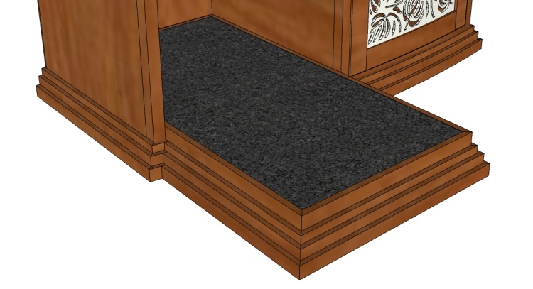
How it's supposed to look
The plan includes a tile-floored section that extends out from the open compartment of the cabinet. It includes a set-in-place wood frame with the 12 x 24" tile mounted in it.
This will provide a more heat-tolerant surface for charging battery-equipped devices.
This will provide a more heat-tolerant surface for charging battery-equipped devices.

The tile and a thick piece of cherry
I bought the tile first so I could build the frame to fit it accurately. Frame pieces will be sourced from this "8/4" piece of cherry.
Chopped up and ready to route
Standard chopping-up procedures ensued, resulting in this selection of parts.
Routing steps into the frame pieces
The thicker pieces get a three-step profile to match the base trim on the cabinet. That was a simple matter of routing as shown here.
Gluing on the long piece
Half of the frame is just a thin section that extends into the cabinet so the thinner pieces were glued on to extend the base sections.
Jigged up to cut miters in the corners
The four pieces forming the frame were to be mitered together. I built a jig to accurately hold the pieces for cutting on the radial arm saw and the end of one of the pieces is being cut at 45° in this shot.
A test fit of the four frame pieces
Despite my careful saw setup the miters were not great (which was resignedly expected) so I touched them up with the disc sander. This shows a test fit of the four pieces.
A recess for the tile routed into the top
Once the fit was good and outside dimensions established, I routed a notch in all four pieces to produce this recess for the tile.
It will eventually go in a bit further than this
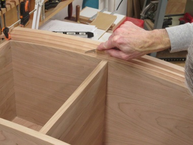
The base pieces were made long with the intent of trimming them to size later. I'd need to trim them to nicely align each step with those at the bottom of the cabinet.
For that I cut a pattern to match the cabinet base profile and then accurately marked where it should be positioned on the frame pieces.
For that I cut a pattern to match the cabinet base profile and then accurately marked where it should be positioned on the frame pieces.
Trimming the step lengths on the base
After removing most of the extra length with the bandsaw, each step was trimmed more accurately with a chisel.
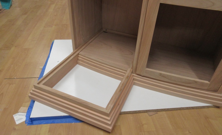
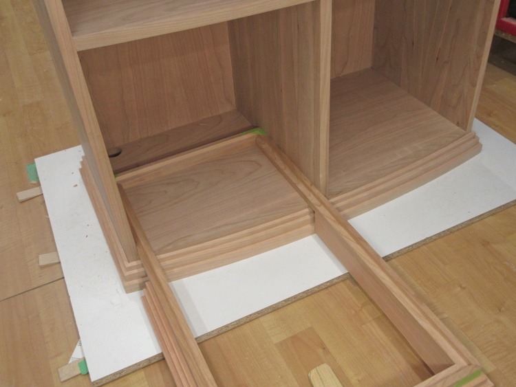
Completed base positioned in the cabinet
In the interests of keeping a much-too-long post from being even longer, I've skipped over the details of:
- finding that I'd made the base too tall,
- sawing the base pieces apart,
- correcting the height problem and
- reassembling the pieces. Then:
- gluing the four pieces of the base together with my customary Mite-R-Gap® technique and
- having to fill all the corner gaps and sand things smooth.
Which then brings us directly to the "base is finished" photo in which the base is shown, finished. Whew.
A Few Details
Next ↓ Previous ↑
Panel Holders
Panel set into back of door frame
The first of the extra bits involves implementing some mechanism to hold the door panels in place.
I decided on narrow backstop pieces that will be pinned into place after finishing.
I decided on narrow backstop pieces that will be pinned into place after finishing.
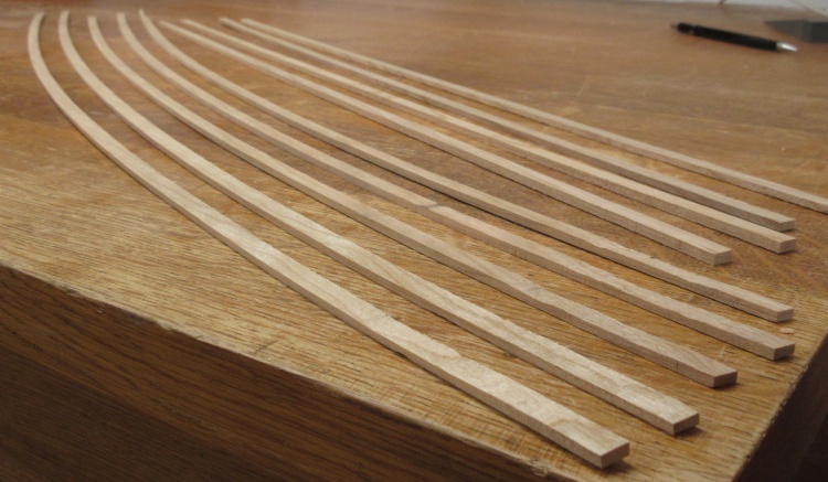
Curved and straight strips made from scraps
I needed both straight and curved backstop pieces to match the frame shapes that composed the doors.
Fortunately I already had properly-curved scraps left from making edging for the shelves. Those, along with some straight scraps were cut to about 1/8" thick and 3/8" wide.
Fortunately I already had properly-curved scraps left from making edging for the shelves. Those, along with some straight scraps were cut to about 1/8" thick and 3/8" wide.
The backstop pieces were cut to length and then an inside edge of each was rounded for a more-finished look. Finally the ends were mitered using the disc sander so the pieces would fit together nicely.
Rounding over one corner
Tiny little miters at the ends
One of the corners with the panel backstops in place
The backstops are (nominally) flush with the back of the door frames and the mitered corners provide a close fit.
The doors, panels and backstop pieces will have finish applied separately so after this fit-into-place session, the backstops will be labelled with their positions and set aside.
The doors, panels and backstop pieces will have finish applied separately so after this fit-into-place session, the backstops will be labelled with their positions and set aside.
Hinges

A sample hinge with associated jigs
For a clean look, I decided to use "invisible hinges" for the doors. These fit between the door edge and the cabinet wall and provide a full 180° opening through a complex-looking linkage.
The hinges require a mortise (AKA hole) that holds the hinge body on each side. Typically a jig is used along with a router pattern-following setup to get a consistent mortise shape.
This shot shows the pattern jig, drill bit for screw holes, a wedge to angle the cabinet-side mortises and a sample installed hinge.
The hinge mortise (less screw holes)
The mortise has wide wings that accept the screws and a deeper center section that houses the hinge mechanism.
The edges of the case follow the front curve and are consequently angled about 10° off square. This presented a bit of a problem since cutting the mortise straight in at the recommended distance from the edge would put the hole corners dangerously close to the front edge as it angled back. To ameliorate the potential disaster of a break-through, I cut the mortises with a 5° angle in the same orientation as the front edge. This was accomplished with a 5° wedge under the pattern jig. The jig and wedge were taped down to the cabinet (which is on its side in these shots) to hold it in place as the mortise was routed out.
For the deeper center portion, a pair of "shortener" pieces were taped in place to restrict the router movement.
For the deeper center portion, a pair of "shortener" pieces were taped in place to restrict the router movement.
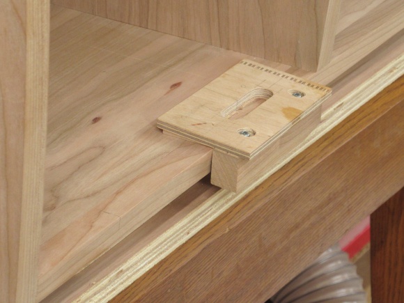
Routing jig taped in place

"Shortener" pieces in place for center section
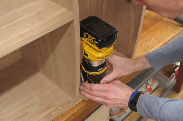
Routing out a hinge mortise
After a couple unsuccessful mortise-cutting trials due to imprecise tools, I borrowed a palm-sized router from a buddy (Thanks Gary!) and made a custom pattern-bit base for it. This worked well, producing an accurate cutting job. In this shot I'm doing a cut on one of the cabinet-side hinge mortises.
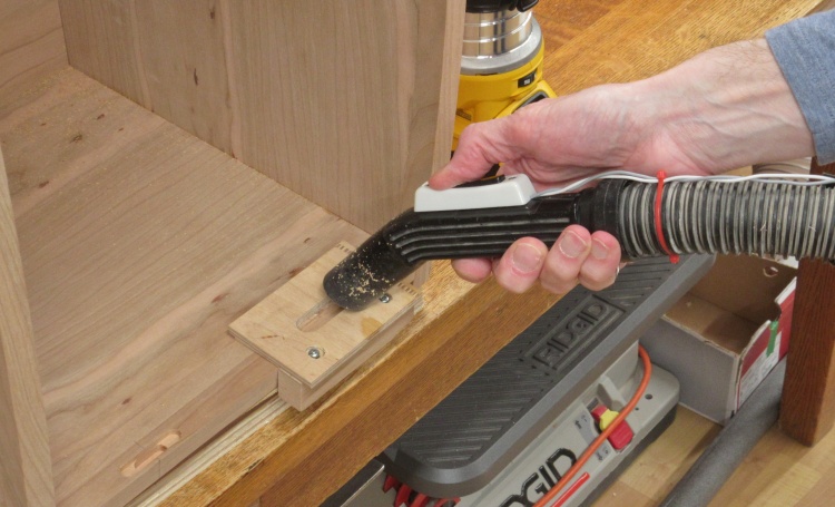
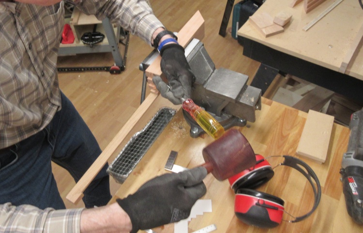
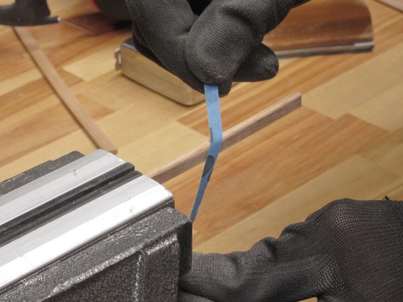
The Revolutionary Instant-On Vacuum
There was no place for chips to go so I cut only about 1/16" each pass. I made a series of cuts to get to the depths I needed with the sawdust needing to be cleaned out after each cut (of which there were 10 or 15 per mortise).
Since I was using the central-vac so often to clean out holes, I rigged up one of the hoses with a push-button switch (doorbell style, since that's the most appropriate of what I had kicking around) to let me turn the system on momentarily.
Since I was using the central-vac so often to clean out holes, I rigged up one of the hoses with a push-button switch (doorbell style, since that's the most appropriate of what I had kicking around) to let me turn the system on momentarily.
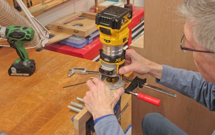
Routing a door hinge mortise
The hinge center locations from the cabinet were transferred to the doors and then the doors mortises were cut using the same technique as before.
The only differences were that I didn't need the 5° wedge and the pattern was clamped to the door instead of taped.
The only differences were that I didn't need the 5° wedge and the pattern was clamped to the door instead of taped.
Installing a set of hinges
Once all the mortises were cut I installed the doors for a test fit. The screws for the cabinet side needed to be ground down since they were too long for the 0.7"-thick cabinet wall.
Door Trimming
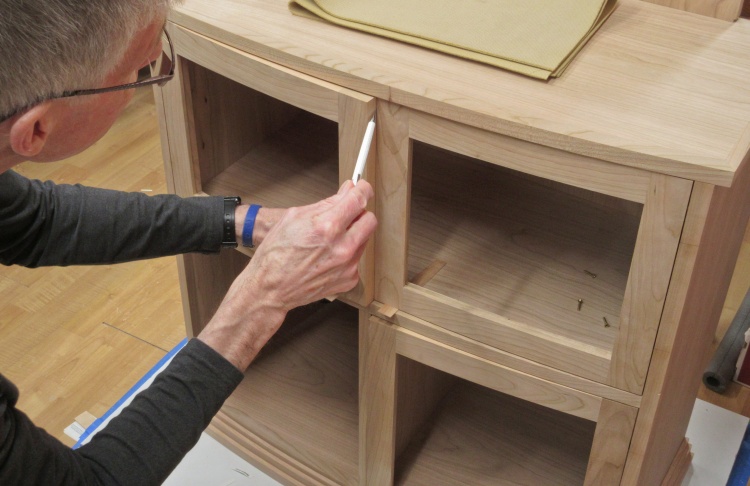
Marking door width
The doors had been made oversized so they could be trimmed to shape. Most of the trimming has already been done by the time of this shot and just the width needed to be adjusted for a small gap in the center.
The left door is already the proper width and I'm marking the overlap on the right door which will then be trimmed to size.
The left door is already the proper width and I'm marking the overlap on the right door which will then be trimmed to size.
Latches
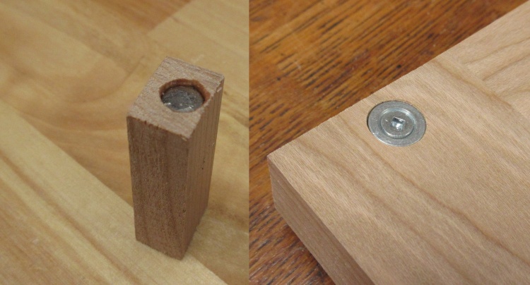
Magnetic latch & door disc
The doors needed some means to keep them closed and I decided to go with shop-made magnetic latchs. I initially made a set of three using 1/4" disc rare earth magnets (specifically neodymium iron boron) but they didn't have quite enough holding power. I switched to larger 1/4" x 1/2" rod magnets (of the same NdFeB flavour) which seemed to do the trick.
This photo shows the magnet in a wooden latch blank and the complementary metal disc screwed into the back of a door.
This photo shows the magnet in a wooden latch blank and the complementary metal disc screwed into the back of a door.
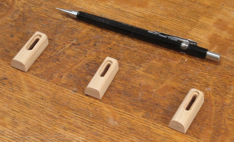
Completed latches
After a bit of shaping, sanding and the addition of a thin veneer cover, the latches were done. This shows the three, complete with a screw slot for potential adjustability.
They are widely spaced in the photo since if they are placed any closer, they jump together to look like this:
They are widely spaced in the photo since if they are placed any closer, they jump together to look like this:
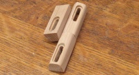
They like to be together
And that was - finally - the end of the woodworking. It took a bit over three months to make the 90-odd pieces required and glue/pin/screw them together.
Finishing
Next ↓ Previous ↑
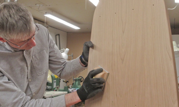
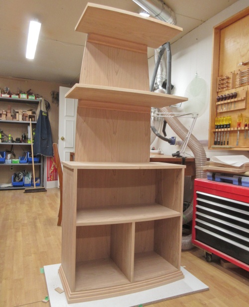
Starting the final sanding
To kick off the finishing, I started by doing a final sanding of all surfaces with 320 grit. This was primarily to remove any marks from fingers or clamps but it also let me inspect all surfaces and also remove any forgotten pencil marks.
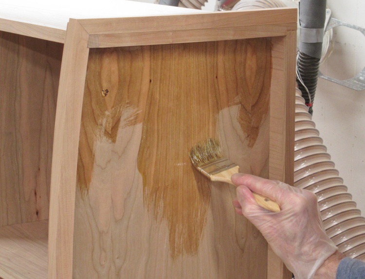
Let the varnishing begin!
I wasn't going to be able to do all surfaces of the cabinet at once so I set it on a table so I could access the bottom, and then started on that with the varnish.
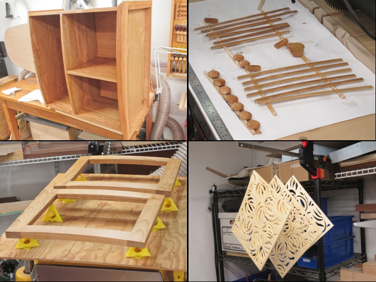
A bunch of varnished pieces
And of course all the other loose pieces got done as well. This composite shows most of them.
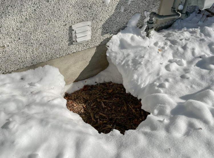
Exhaust fan excavation
I had installed an exhaust fan in the shop a few years ago so I could vent odours when applying finishing. It needed to stay on throughout the whole process which took about a week. We'd had something like 50 cm of snow just before I started the finishing and within a day the warm exhaust had evaporated all the snow right down to the mulch.
Of course all that nice heat isn't free. A bit of calculation suggests that running the fan pumps out about 1200 W worth of heat along with the air (not to mention the, um, 7 W for actually running the fan). So my one-week finishing process will increase my March heating bill by maybe 6%, and while that seems like a lot for running a fan it's probably fairly reasonable for decent air quality in the house. If only I had a way to direct that air onto the icy driveway...
Of course all that nice heat isn't free. A bit of calculation suggests that running the fan pumps out about 1200 W worth of heat along with the air (not to mention the, um, 7 W for actually running the fan). So my one-week finishing process will increase my March heating bill by maybe 6%, and while that seems like a lot for running a fan it's probably fairly reasonable for decent air quality in the house. If only I had a way to direct that air onto the icy driveway...
Final Assembly
Previous ↑
Installing panels
Once all the finishing was done, I just had to do the final assembly.
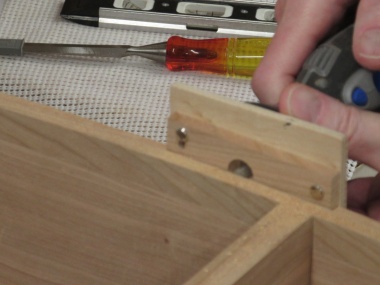
First up was to install the panels in the door frames. Here I've drilled holes through the backstop pieces and into the frame edges. Half-inch common nails are inserted to hold them in place.
First up was to install the panels in the door frames. Here I've drilled holes through the backstop pieces and into the frame edges. Half-inch common nails are inserted to hold them in place.
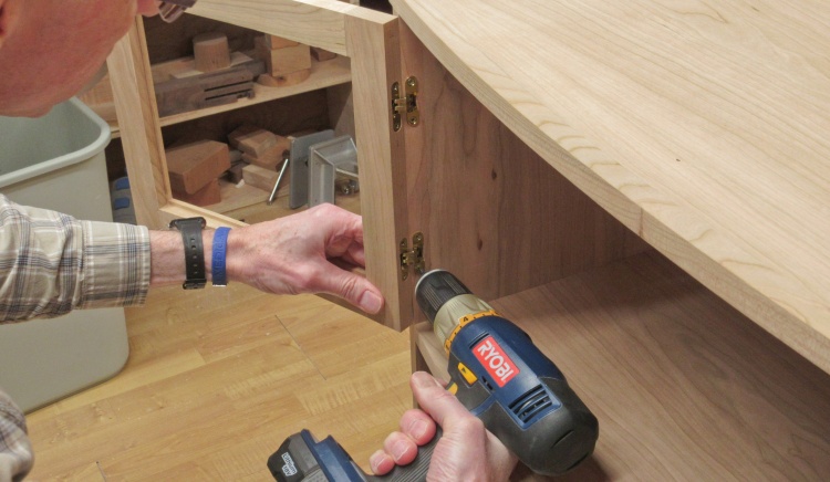
Adding a door
Hinges were installed in the doors and then into the cabinet sides.
Once the doors were in place, the magnetic latches could be accurately located and attached to the cabinet using screws (to allow for some adjustment if necessary).
Once the doors were in place, the magnetic latches could be accurately located and attached to the cabinet using screws (to allow for some adjustment if necessary).
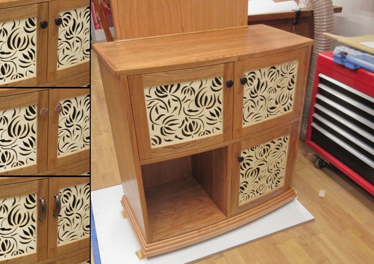
Door pulls in place
I wanted to look at a few options for the door pulls and bought three styles that I thought might look good. I taped each set to the cabinet in sequence and took photos that would allow me to do a side-by-side comparison.
We decided to go with the black cast-iron pulls since they had a nice contrast to the cherry.
We decided to go with the black cast-iron pulls since they had a nice contrast to the cherry.
Final assembly consisted of screwing the shelves in place, covering the screw heads and taping on the power bar. This is the look after setting it in place (and clearing off the side of the filing cabinet).
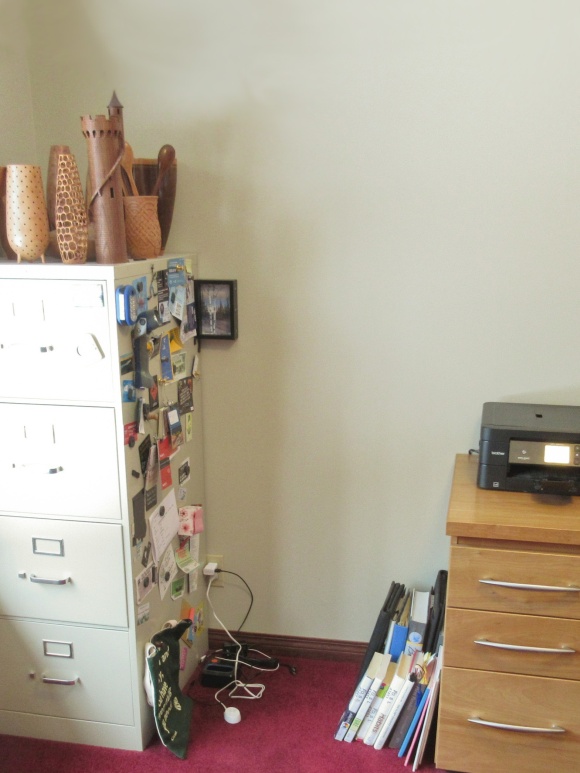
Before
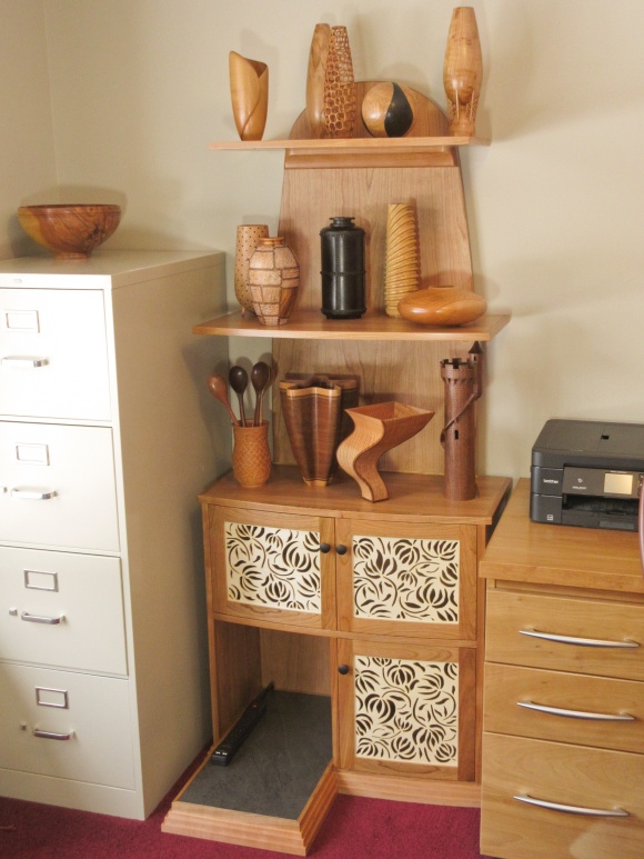
After


