My brother-in-law and family moved to an acreage recently and along with my niece's horse there reside another two horses, one of which is a Clydesdale named Connor. Connor isn't the ideal riding horse since he looks like he's about three feet wide, but he has the build and training for pulling (and has a nice personality to boot). He also has paraphanalia, and one of the items is a two-wheeled horse cart. Unfortunately the cart was made for a horse of more modest proportions than a Clydesdale, so the wooden shafts were too short and tended to poke him when he turned. I was enlisted to help solve this problem which equated to the construction of new shafts and I also volunteered to make new arms for the cart seat after seeing how pathetic the old ones were.
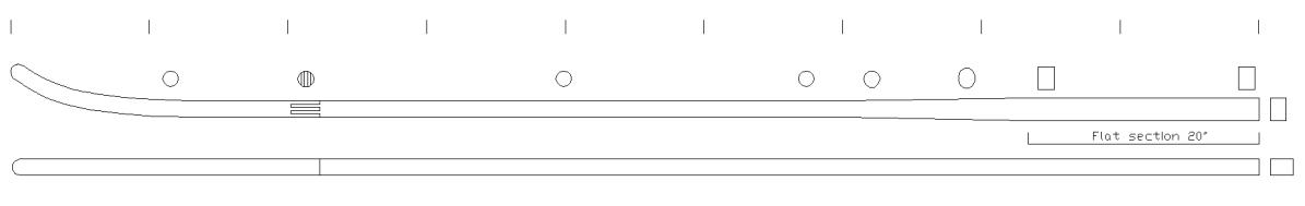
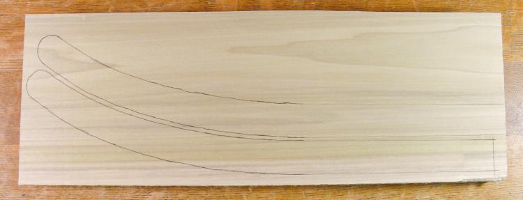
Your basic shaft. The tick marks are 1' apart.
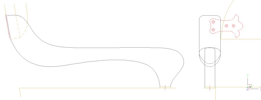
And your basic curvey arm
Shafts
The shafts are modelled on those of another piece of Connor's paraphanalia, the classic one-horse open sleigh. As an aside, I will point out that someone describing the movement of Connor pulling the sleigh with four people aboard would be unlikely to use the phrase "dashing through the snow", as he sets a determined but let's say - unthreatening - pace. But I digress. Based on the sleigh example we decided to make the shafts extend about 8 feet past the front of the cart, so with some extra length to be used to bolt them on, the length came to 9 feet.
After some discussion and consideration of the optimal wood to use, the amount required and the best construction, I ended up using Birch since it was knot-free, reasonably strong, available in large enough planks and as a bonus was reasonably priced compared to other hardwoods.
After some discussion and consideration of the optimal wood to use, the amount required and the best construction, I ended up using Birch since it was knot-free, reasonably strong, available in large enough planks and as a bonus was reasonably priced compared to other hardwoods.
General cart configuration
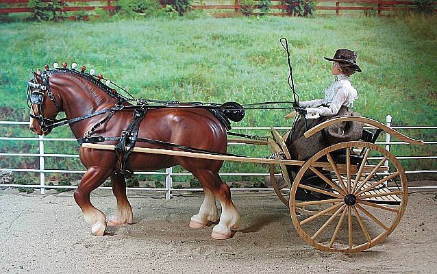
So just to place the shafts in perspective for those few among us who may be unfamiliar with draft horse harnessing, I will direct your attention to the "General Lee Draft Show Harness" model copied from the website of the venerable International Model Equine Hobbyists Association Inc. Which, as far as I can tell seems to have competitions like horse shows, only with sent-in photos of models rather than actual, you know, horses.
At any rate you can see this fine Breyer Clydesdale (apparently distinguished by small incandescent bulbs on his mane) pulling a cart not completely unlike the one the shafts are for.
At any rate you can see this fine Breyer Clydesdale (apparently distinguished by small incandescent bulbs on his mane) pulling a cart not completely unlike the one the shafts are for.
Of course the shafts are the long wooden poles extending from the cart to beside the horse. In practise the rigid shafts allow the horse to turn the cart and also to slow it down. The shafts go to either side of the horse and are often curved outwards at the front (but not in this model) to give the horse more room to turn. The shafts are not used to actually pull the cart; that is accomplished with stout leather straps ("traces") connected from the horse's harness to the cart. Or more specifically to the whiffletree of the cart (or whippletree or singletree or even swingletree). Ya gotta love the terminology.
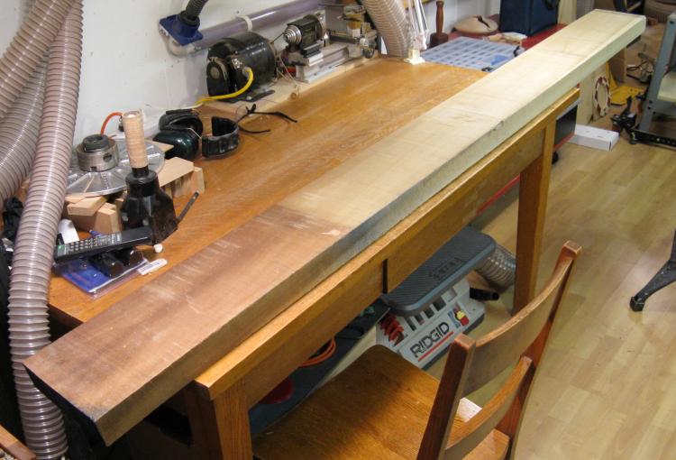
Birch plank
As the plan shows, the shafts are each made of two sections since I wasn't able to find any pieces of wood quite long enough.
The specimen shown here is a bit over 7', which was fine for the two-piece approach. It was also just over 2" thick which worked well for the desired width of the shafts.
The specimen shown here is a bit over 7', which was fine for the two-piece approach. It was also just over 2" thick which worked well for the desired width of the shafts.
Slicing off a section
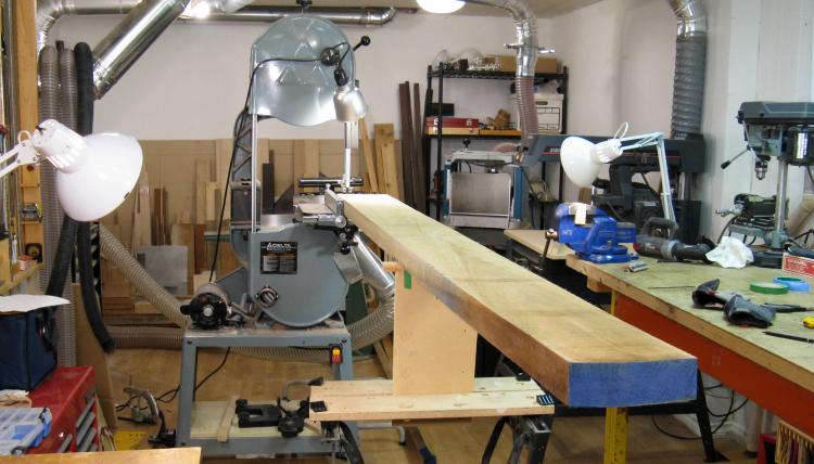
With a bit of rearrangement I was able to make enough room both ahead and behind the bandsaw to fit the board. I have a couple of adjustable rollers to support the wood but they are both behind the saw so I jury-rigged another with a Workmate and some scrap wood for the front.
Two slices ready to go
Here the two longer pieces have been cut off. The plank was pretty flat but it still had a bit of thickness variation and warp.
Normally the jointer can be used to straighten the edges of a piece of wood but the length of these made that impractical.
Normally the jointer can be used to straighten the edges of a piece of wood but the length of these made that impractical.
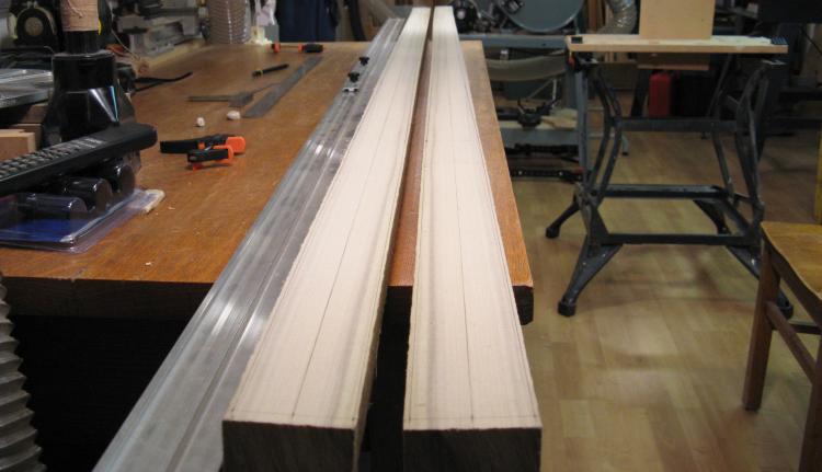
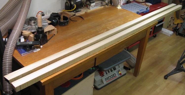
Straight sides marked
To make straight shafts and with the proper contour, a centerline and outlines were marked using the long aluminum straightedge shown beside the boards.
The finished shafts would be a consistent height but the width varies from 2" at the mounting end to 1.375" for most of the length of the shaft, with a section about 20" long where the shape transitions between the two profiles as in the foreshortened outline below.
The finished shafts would be a consistent height but the width varies from 2" at the mounting end to 1.375" for most of the length of the shaft, with a section about 20" long where the shape transitions between the two profiles as in the foreshortened outline below.
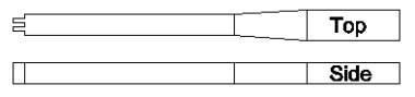
Like this, but longer
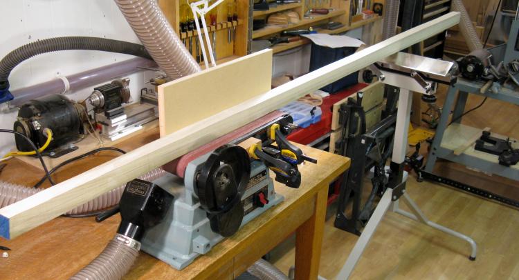
Sanding the edges to shape
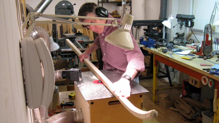
The first step was to cut the width of the shafts to the marked profile by hand using the bandsaw. The next step shown in this photo was to sand the resulting imperfect edges down to the line. I rigged up the belt sander with a flat wall to make sure the sanding was at right angles to the sides, and then just moved the shaft by hand. This let me get the shape pretty close to the lines.
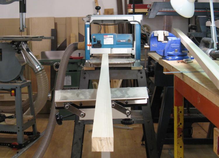
Planing to width
After the side profile was correct the shafts were run through the planer to give the top/bottom direction a consistent 1.375" thickness.
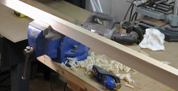
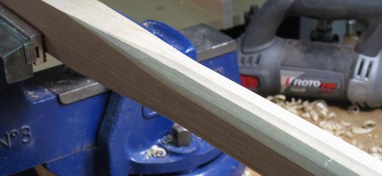
Hand planing the slope
Since the sanding was less effective when shaping the angled portions, I needed to touch up those sections where the width changed from 2" to 1.375". I was able to use a small block plane and a spokeshave to smooth those regions out.
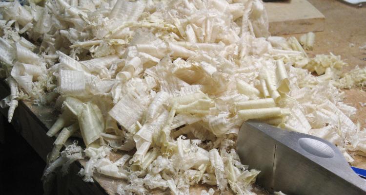
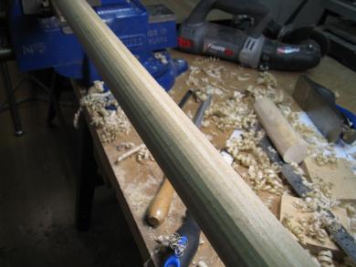
Gratuitous shavings photo
...which made some nice 1.375"-wide shavings.
Marking the curved ends
The next step was to make the curved ends. A shorter piece of the Birch was marked with the profiles of the two ends as shown here.
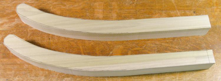
Ends cut out
Then they were cut out close to the lines with a bandsaw;
Sanded to proper outline
And finally sanded to the finished profile using a belt sander.
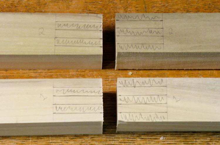
Marked for joints
Next, the two pieces of the shaft would need to be joined. I decided to use a square finger joint since that would give a fairly strong connection.
Here the ends of the four pieces have been marked.
Here the ends of the four pieces have been marked.
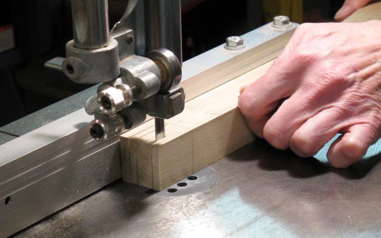
Cutting joint fingers
The bandsaw with a carefully-set-up fence was used to cut the edges of the fingers.
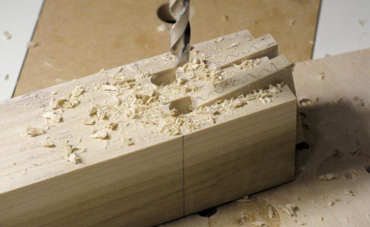
Removing fingers
And then the drill press was used to essentially cut off the fingers, leaving just a bit of wood at the ends of the slots to trim.
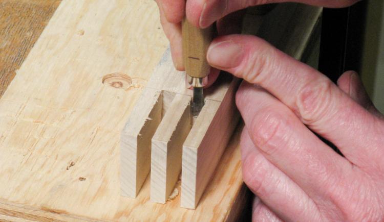
Trimming ends
The trimming was done with a small flat chisel, working from either side.
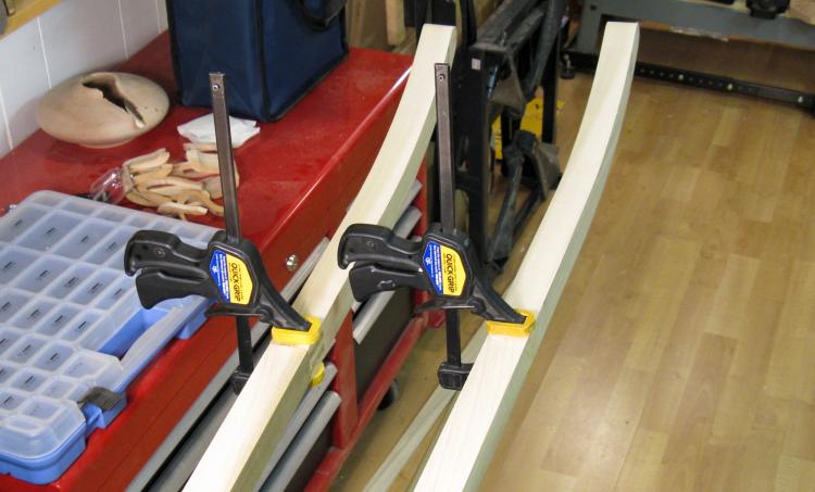
Gluing the curved ends to the longer pieces
And then with the joints all trimmed, the pieces were glued, assembled and clamped.
Routing corners
So now there are two shafts of the proper length and shape but they still have a rectangular cross-section. The ends that bolt to the cart need to be rectangular, but the rest needed to be round or oval.
Ideally I could run it through the router with an appropriate 1/4-round bit but with a cross-sectional width of 1.375", that would mean one with a radius of 11/16". I didn't have one of those so rather than try to find that rare (or nonexistent?) item, I decided to just bevel the corners and then complete the rounding by hand.
Here I'm adding a 45 degree bevel to the corners on the router table. The bevels are evident at the near end of the wood.
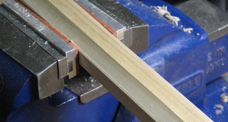
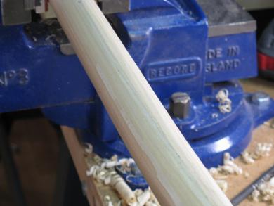
8-sided(ish) after routing
The bevelling operation made the shafts (almost) octagonal. The largest bevel bit I had wasn't actually quite wide enough and it left a small ridge so I removed that first using the spokeshave.
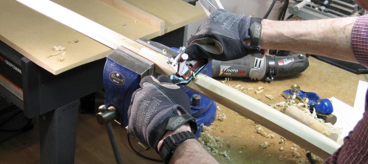
Using a spokeshave on corners of 8-sided shaft
Here I'm starting to shave the corners off the octagonal shape.
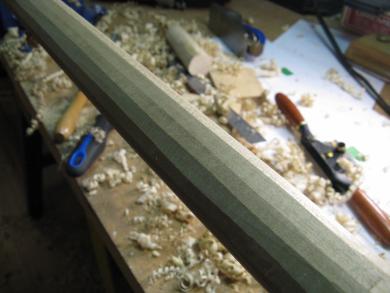
16-sided
32-sided
Almost round
This little montage gives your scrolling finger a well-needed rest and shows the shape as it progresses from the octagonal of the previous picture to hexadecagonal to (supposedly) triacontakaidigonal, and then to almost round.
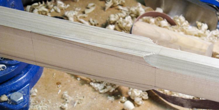
Rectangular-to-oval segment
Meanwhile, back at the mounting end, the rectangular section needed to be blended into the rest of the shaft. Here the corners are marked to have the radius transition from zero to the size used on the rest of the shaft.
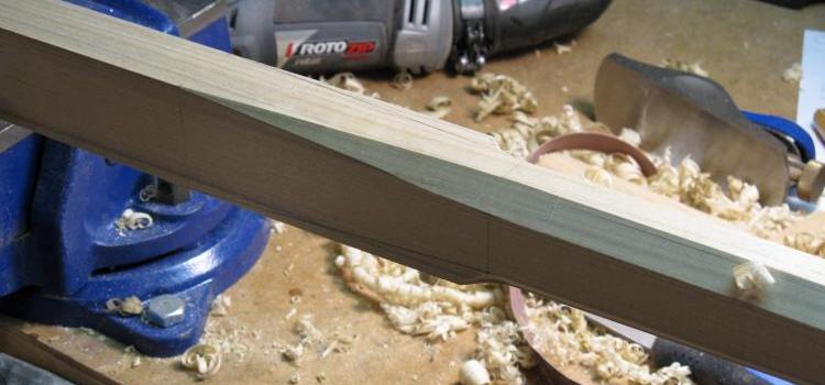
Slope made
The 45-degree bevel has been added...
Slope getting rounded
...and then the rounding continues like the rest of the shaft.
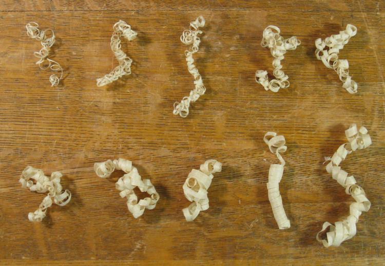
A nice sequence of shavings
Shaving the corners made a nice selection of curly shavings that varied in width as the corner was flattened out. It took about 10 strokes to get to the desired depth on the octagonal shape and here I put aside one 10-stroke sequence of shavings just for the heck of it.
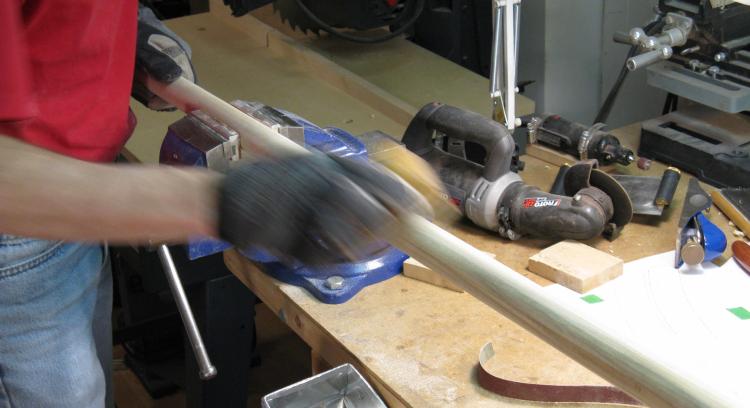
Starting to sand smooth
The last step to the rounding was to get rid of the remaining small facets and here is a nice blurry shot of using a sanding block to do so.
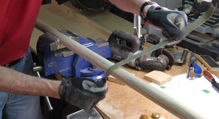
Sanding with strips
...and some more sanding with sturdy strips cut from belts for a power sander to help round the shaft.
And that was pretty much it for the shaping of the cart shafts. Except that they were pretty plain. And they weren't needed just yet. And I didn't really have another project to start on. So I thought maybe I'd do a bit of carving.
And that was pretty much it for the shaping of the cart shafts. Except that they were pretty plain. And they weren't needed just yet. And I didn't really have another project to start on. So I thought maybe I'd do a bit of carving.
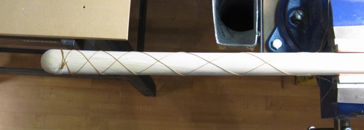
Using string as a marking guide
This shows a pattern outlined on the end using string. The ends don't need much strength so it shouldn't hurt to have some wood removed.
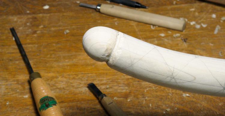
Starting to carve the end
The pattern was transferred to the wood using a pencil and then I began carving grooves starting at the end.
The end looks unfortunately phallic at this partially-done point but further carving moved it solidly towards the "decorative" end of the spectrum.
The end looks unfortunately phallic at this partially-done point but further carving moved it solidly towards the "decorative" end of the spectrum.

Basic pattern done
Here the grooves have all been cut on one shaft, with decreasing depth as they go along.

Shaping the notches
The grooves were widened and rounded using files and then smoothed using sandpaper.
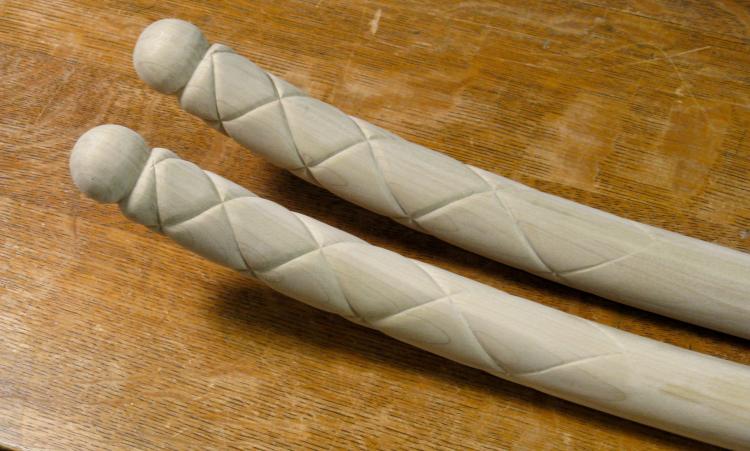
Ends done
These are the completed ends. I'm sure that a classy horse like Connor will be able to appreciate them.
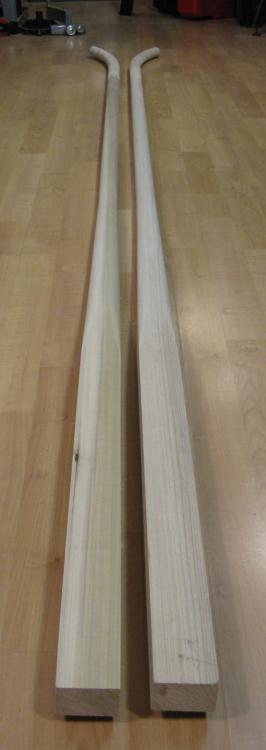
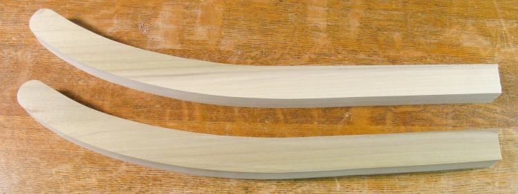
Completed shafts
And here is the completed pair of shafts.
Arms
The cart has a short seatback with a separate higher backrest that mounts on a center bracket. The "arms" that it was fitted with were really more brackets to prevent the backrest from pivoting. One which I assumed was the original consisted of a 3/8" metal bar bent and fastened at each end. It attached to the backrest with the upholstery leather formed neatly around it. On the other hand (literally) the second arm was an obvious replacement, being a flat rusty metal strap screwed directly to the backrest.

Backrest with current arms (upside-down)
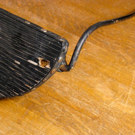
Probably the official arm
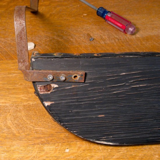
The imperfectly-matching replacement
My original intent was to replicate the steel arm (a little threading, a little tapping, a little bending - how hard could it be?). However I changed my mind after disassembling it since it looked like it would be a fair amount of work and anyway the steel rod seemed like an inferior approach to an arm rest.
It may surprise those familiar with these pages that making wooden arms was not actually the first option I considered. However wood was certainly the lowest-risk approach and should result in some decently-shaped arms with adequate backrest support. So I bowed to the inevitable and started looking at some designs.
It may surprise those familiar with these pages that making wooden arms was not actually the first option I considered. However wood was certainly the lowest-risk approach and should result in some decently-shaped arms with adequate backrest support. So I bowed to the inevitable and started looking at some designs.
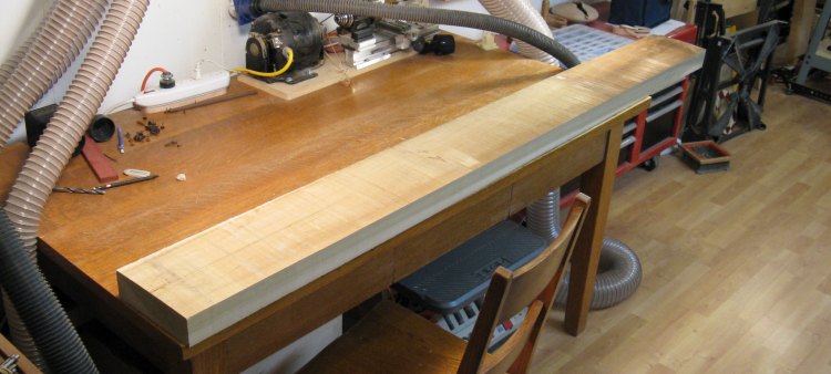
The leftover Birch
I still had a goodly percentage of the Birch we obtained for the shafts, so that seemed like a fine choice. This is what remained after a couple shafts were taken out of the original plank.
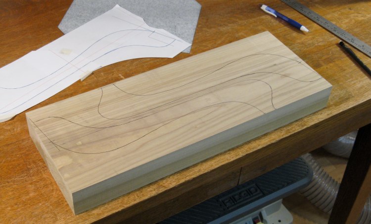
Arm outlines marked
I used my normal technique of a full-sized paper pattern traced onto the wood with carbon paper.

Sanding the arm outlines to shape
After cutting out the arms close to the lines with a bandsaw, they were then sanded down to the marked lines using the spindle sander shown here.
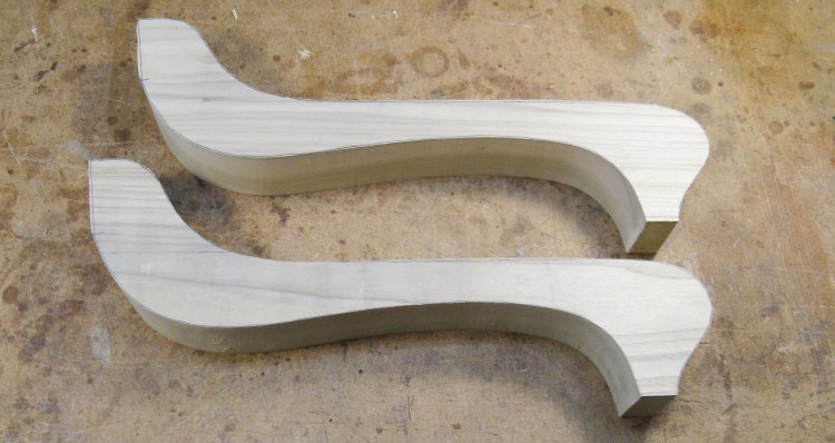
The arms with the proper outlines, ready for further shaping
The arms were thicker than I needed, so after this shot they were trimmed narrower on the bandsaw and run through the planer to remove the saw marks and equalize the thicknesses.
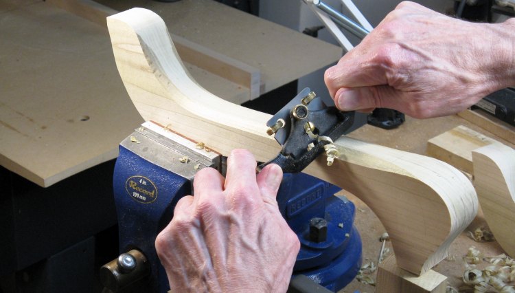
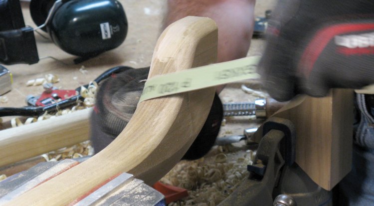
Starting the shaping
For rounding off the corners of the arms, I went back to the spokeshave again and did the bulk of the basic shaping.
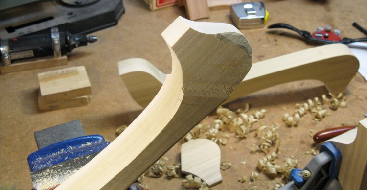
Trimmed end
The ends needed to be a bit narrower than the rest of the arm, so the front sides were sawn off as shown here.

The rasp chewing off a corner
Some of the edges that were a bit too curvy for the spoke shave were shaped with a round microplane rasp.
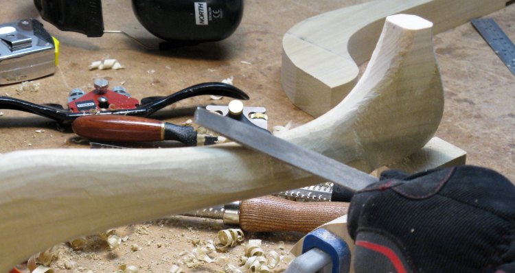
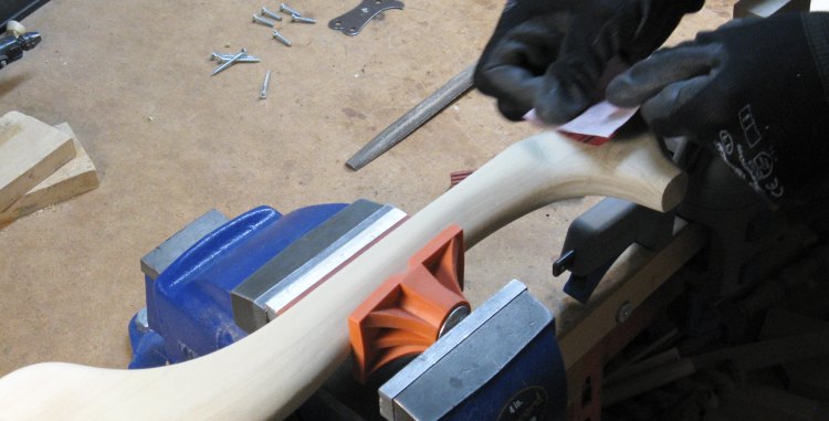
Filing off visible tool marks
And some of the rasp and spokeshave marks were smoothed out a bit with a coarse file.
Rounding everything off
And then some of the file marks were smoothed out a bit more by sanding with 100 and 120 grit to round everything off;
Some final sanding
And lastly some finer sanding with 120 to 150 grit where there were still visible marks or scratches.
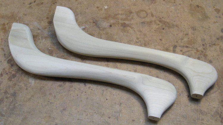
Completed arms
I drilled some mounting holes in the bottom, and the arms were complete. The plan is that the opposite ends will be trimmed to fit the exact distance and angle to the backrest when they are all installed on the cart.
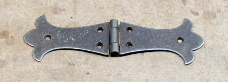
Hinge used for brackets
The arms are made to mount beside the backrest and will be held in place with screw-in brackets. I wanted something a little more old-timey-looking than a square bracket, but there isn't much choice out there.
However I was able to find a suitably ornate hinge that I figured could be modified into a couple brackets.
However I was able to find a suitably ornate hinge that I figured could be modified into a couple brackets.
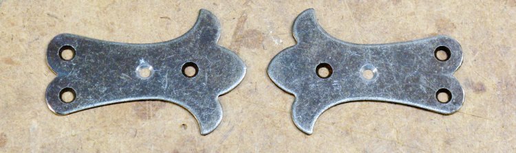
Mounting brackets
After a bit of cutting, grinding and drilling, I ended up with these two brackets, with contours suitable for the rear end of a cart.
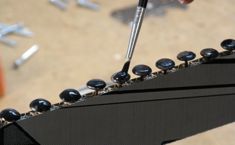
Painting tacks
About all that was left to do before cart assembly was to tack the leather trim back on to the backrest. Many of the old tacks were bent and rusted and the only replacements I found were brass rather than the black of the originals. So rather than searching further afield, I just painted the heads black as shown here (and also touched up some old tacks I was going to reuse).
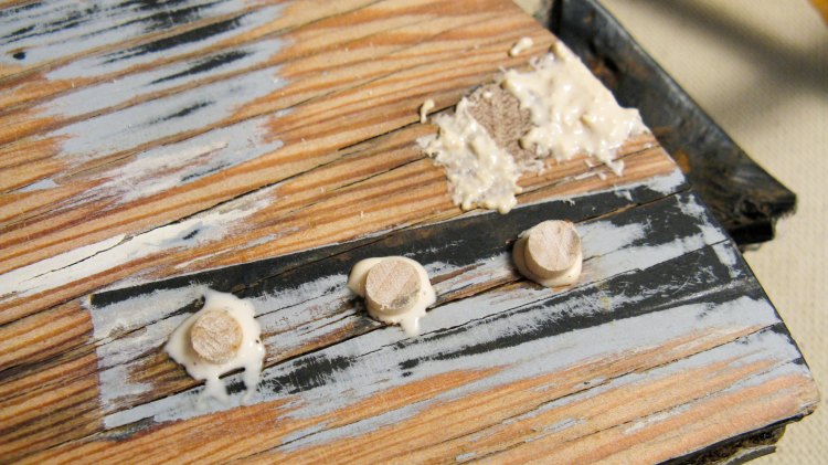
Filling holes on backrest
The backrest had some sizable holes from the previous arms, so I filled those to give a flat surface that could be painted.
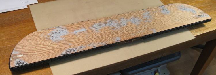
Backrest ready to go
The backrest had its old crackey paint sanded off and the filled holes smoothed over. I used the new and rejuvenated tacks to reapply the leather trim.
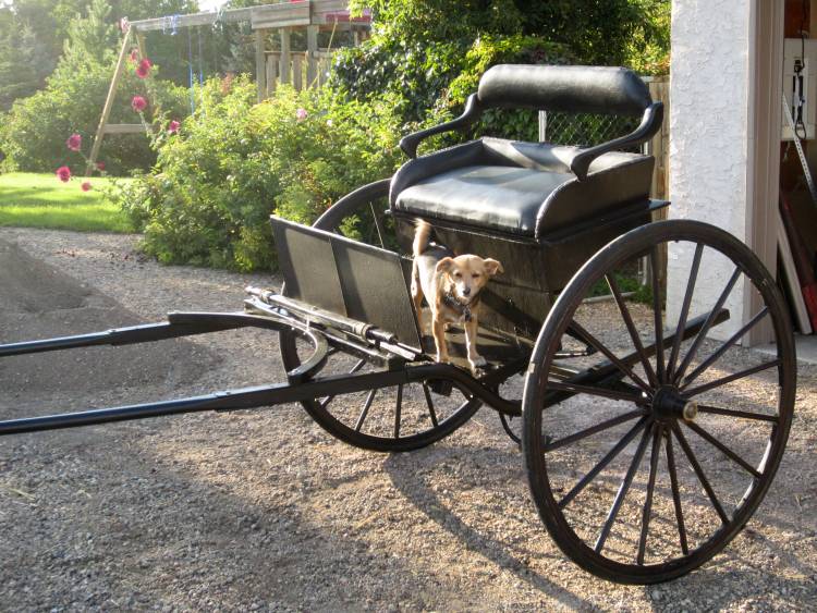
Completed cart, cargo end
The parts were painted to match the rest of the cart and then one fine day, we put it all together.
The arms were screwed on to mounting plates at the front, and were held to the backrest by the fancy brackets.
The shafts had the breeching Ds added (more great terms), and the shafts were spaced, drilled and mounted.
Here Charlie looks like he's ready to go for a ride. Or more likely he saw a black leather seat and decided it needed dusty paw prints on it.
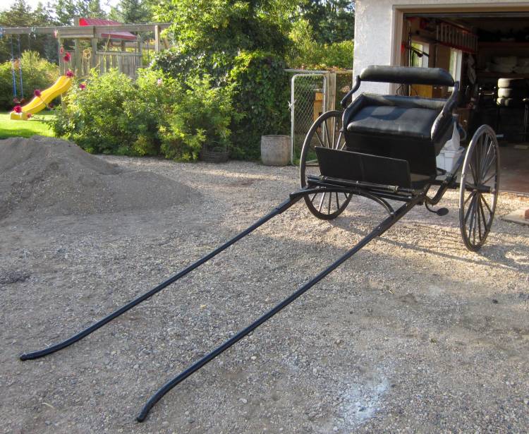
The full shafts are not as long as they look here
This view shows the full cart. We ran out of time that day to hook it up to Connor and take it for a test drive, but hey - what could possibly go wrong?


