I have to admit that the antique-style cherry chair does not really match anything we currently own, except maybe peripherally - we have some cherry furniture, and some antique (or antique-looking) furniture, and for that matter, some chairs. And we didn't actually need another chair. But the compound curves of the rear legs interested me, as well as the style of carving on the top rail and back. That being said, I think it is safe to say that it will not be the humble beginnings of a future 8-piece matching dining room set.
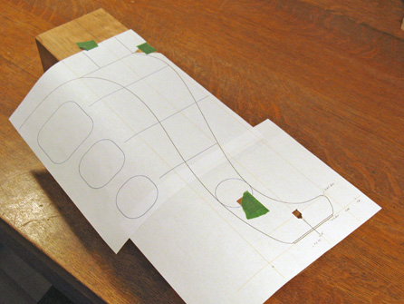
As usual, I started out with a plan that I could use to investigate design ideas, and then also use to print out 1:1 templates for cutting and carving.
As usual, I started out with a plan that I could use to investigate design ideas, and then also use to print out 1:1 templates for cutting and carving.
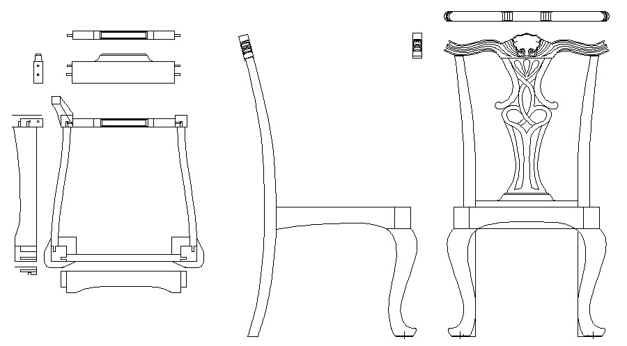
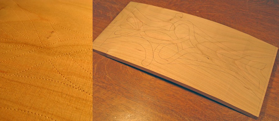
This was the final look of the plan. This is the basic outline view, but the drawings include other details such as the size of the wood stock required, carving depths and contours, etc. The time required to do the drawing was not included in the times I give for making the chair.
Wood
Reportedly much of the best Chippendale furniture was made from mahogany imported from the West Indies. However, I wasn't really interested in authenticity. And while I have nothing against South America or the Caribbean, I'm not a big fan of the look of mahogany, so I used black cherry for the chair since I thought that the grain and colour would complement the design.

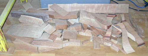
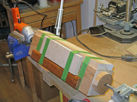
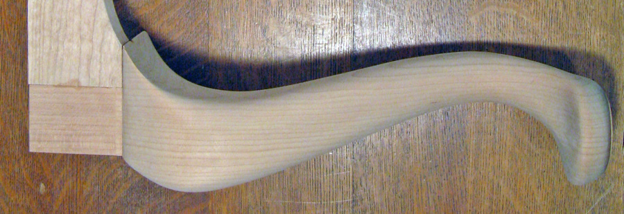
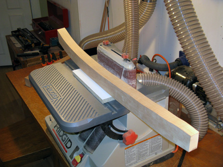
Given the curvature that I wanted various parts of the chair to have, fairly large pieces of wood were required. Many wood chairs have curved back legs, but when you look at them closely, most turn out to be curved in only one plane, meaning a flat plank an inch or two thick can be used as the raw material. Having curves in two dimensions mean that both dimensions of the wood blank need to be sizable. In this case, the back legs needed to be at least 4" x 2.6" finished size, and the front legs 4.1" square finished size.
Unfortunately, anything above 2" becomes more difficult to source, and going over 4" reduces the number of suppliers further. Fortunately I was able to find the wood I needed at A & M Wood Specialty Inc. in Cambridge Ontario. Not only did they have the sizes I was looking for, but the wood they provided was of excellent quality and generously sized.
The photo shows the rough stock used for the chair. In this shot, the top is already complete and the back splat is roughed out. Admittedly, the legs and rails still need a bit of "finishing sanding".
The photo shows the rough stock used for the chair. In this shot, the top is already complete and the back splat is roughed out. Admittedly, the legs and rails still need a bit of "finishing sanding".
Top Rail
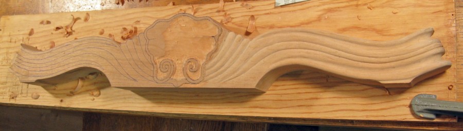
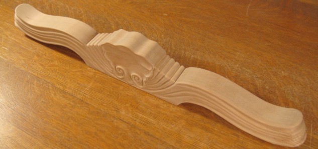
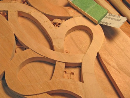
As is my usual habit, I started with what I thought might be the hardest part of the chair, which in this case was the top rail (although the back splat gave it a run for it's money). The rail was cut out and the outline was shaped as far as possible with bandsaw, spindle sander and files. Then I traced the contour pattern onto the faces and worked on giving them some depth. The first photo shows the rail with most of one end of one side roughly carved out, and the next is a closer shot of the center "shell" portion, just started. The bottom shot is of the completed top rail.
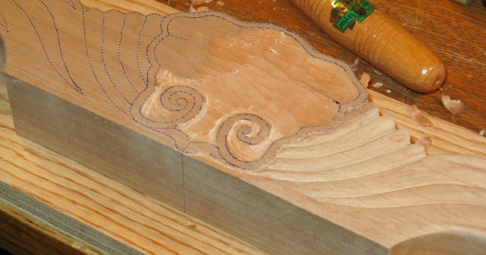
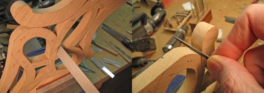
As can be seen from the slightly distorted photo below, I used a fairly wide selection of tools for carving. They range from a cheapo carving set (but with decent blades) to specific tools that I acquired individually. I had also made a custom scraper (not in this picture) to help with the narrow notches in the part, but with practice I was able to carve them using an appropriate chisel, which gave cleaner results.

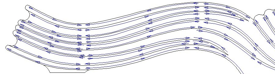
The cherry cut fairly nicely with sharp tools, but when carving a curved shape, the direction of carving is different for every part of the curve, so nice big, long, luxurious shavings were just not in the cards. And inattention to where exactly was being carved could lead to big unwanted slices and the "oh crap! Hope I can sand that out" syndrome. The diagram below gives an idea of carving directions. And yes, I was able to sand most of my goofs out.
To keep the tools sharp, I mostly used a motorized leather belt. I would charge the belt with honing compound and run the tools against the belt for a
few seconds every 5 or 10 minutes of carving. This was enough to keep them razor sharp. I don't think I ever had to reuse the sharpening stone on the tools.
The top rail took just under 40 hours to complete, including the sanding (every hour of which feels like two). As usual with oddly shaped pieces, a number of custom sanding aids were required, from "standard" sanding forms of various curvatures to little sticks with custom-shaped ends to position small strips of sandpaper to ensure ridges were sanded with the grain.
The top rail took just under 40 hours to complete, including the sanding (every hour of which feels like two). As usual with oddly shaped pieces, a number of custom sanding aids were required, from "standard" sanding forms of various curvatures to little sticks with custom-shaped ends to position small strips of sandpaper to ensure ridges were sanded with the grain.
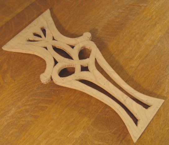
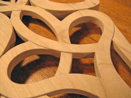
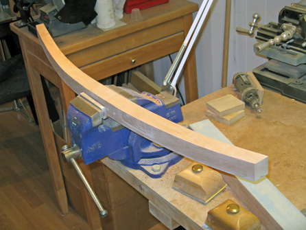
Back Splat
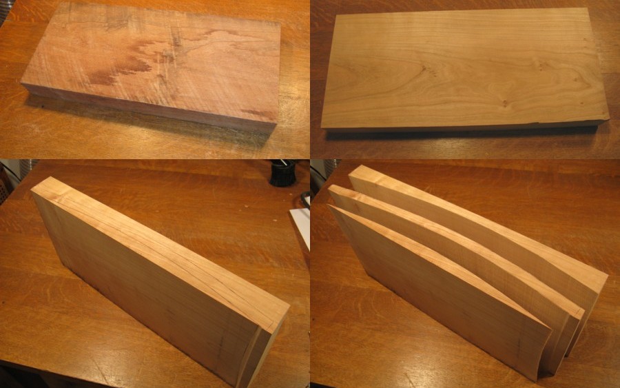
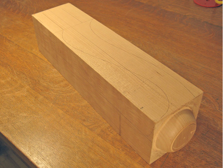
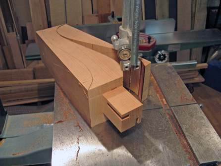
I worked on the back next. As the montage shot shows, I started with a cherry plank and cut a curved blank out of it, making it the back splat blank plank.
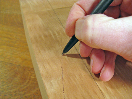
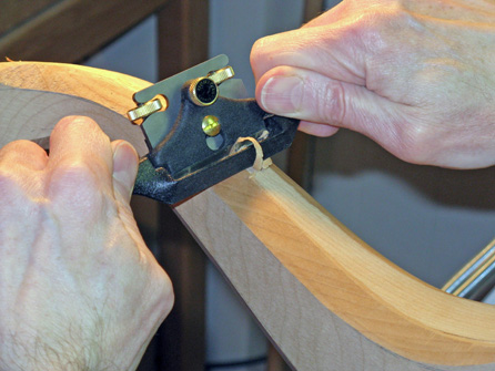
The pattern was then transferred to the blank using a pounce wheel (there is a picture of the wheel down further). The wheel produces indents in the wood along the outline, which I then use as a guide to ink in the pattern.
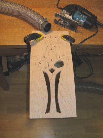
As the picture below shows, I drilled starter holes and then used a hand-held jig saw to cut out the unwanted sections of the blank, which would later be smoothed by hand.
A friend of mine once described the jigsaw as something like "the maximum amount of noise for the minimum amount of effect", and that was indeed the case with my previous low-end (B&D) jigsaw, which I had owned for many years. However, it failed to fail, so to speak, so I never had a good justification to replace it. However, I finally managed to build up a high-enough pile of rationalizations, and armed with those, bought a new, higher-end model. And it is like night and day. It cuts several times faster, and with (slightly) less noise and much less vibration. It still isn't the ideal tool for ripping a 4x8 sheet of plywood, but I no longer wince at the thought of making a 6" cut with it. But I digress.
A friend of mine once described the jigsaw as something like "the maximum amount of noise for the minimum amount of effect", and that was indeed the case with my previous low-end (B&D) jigsaw, which I had owned for many years. However, it failed to fail, so to speak, so I never had a good justification to replace it. However, I finally managed to build up a high-enough pile of rationalizations, and armed with those, bought a new, higher-end model. And it is like night and day. It cuts several times faster, and with (slightly) less noise and much less vibration. It still isn't the ideal tool for ripping a 4x8 sheet of plywood, but I no longer wince at the thought of making a 6" cut with it. But I digress.
The openings were then more-accurately sized using a combination of spindle sander, files and sandpaper. I made curved wooden forms with a variety of diameters to work as forms for the sandpaper.
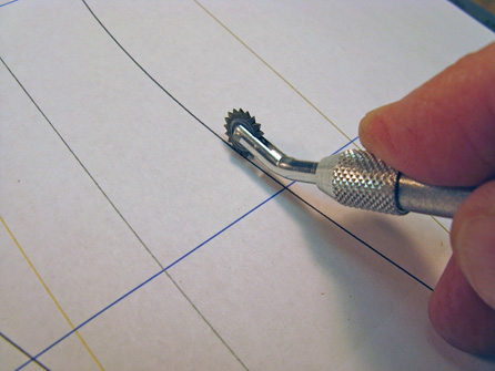
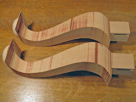
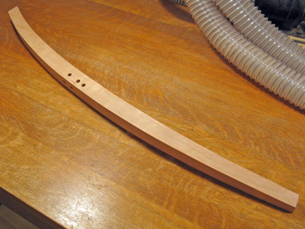
The next step was to contour the various parts of the back relative to one another. To aid in that, I had first determined the depth at strategic points from the outside face of the blank. Then, using a drill press, I drilled depth-guide holes using a flat-bottomed milling bit to the required depths, showing how far down I should carve each section. The holes that can be seen below have a value beside them that represents the depth in millimeters.
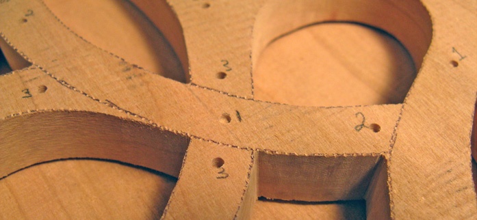
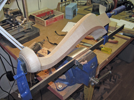
Then it was the work of maybe 6 or 7 hours to carve the front side of the back to the appropriate contours.
The process was then repeated for the rear side of the back splat as well. That took only 4 or 5 hours, so I must have been getting better. When that was done, the sanding then ate up 14 or 15 hours.
Front Legs
I started by turning the feet on the front legs. The wood was cut to length, and I marked the position of the foot. The center of the foot is offset from the center of the blank due to the leg shape. This made things a bit trickier, but the alternative was either a smaller leg or a larger blank, neither of which I wanted. I cut away the excess wood around the foot to minimize the amount of wood I would need to remove. With a regular lathe and turning tools, this would not be necessary, but I didn't have a suitable lathe, and the offset foot complicated things a bit. In lieu of proper equipment, I jury-rigged a lathe using a variable-speed hand drill in a bench vise. The other end used a tailpiece with a live center that I removed from a small lathe I have. This was clamped to the bench at the appropriate distance from the drill.
In order to turn the legs, they needed to be balanced around the spin axis. The blanks had two thicker sides and two thinner sides, so to balance the legs, I added counterweights to the two thinner sides. This would be necessary if a regular lathe was used too, except the counterweights would need to be much more firmly attached due to the higher speed. In this case, I was able to just tape them on since the piece was spun relatively slowly. Of course, in the shot below it looks like it is going at a pretty good rate, but it is a 1/25 second exposure, and the piece actually turned only a fraction of a revolution during the exposure.
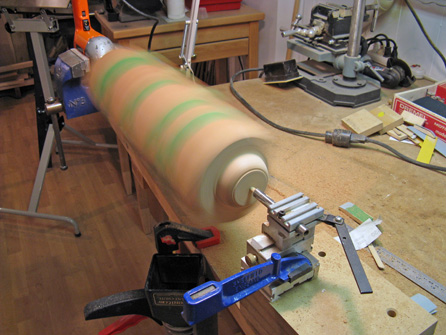
Due to the low speed and the limited strength of my make-shift setup, I didn't use regular (edged) turning tools. Instead I employed a Dremel tool with cutting and abrasive bits. I hand-held the Dremel (usually braced against the tailstock assembly) and used that to shape the feet. This provided the cutting action with very little radial force on the setup, and as a bonus basically eliminated any danger of tear-out from a tool catch. Of course, it was also pretty slow going.
Once the feet were shaped and sanded, I traced the leg shape onto two of the sides. As before, I used a printed-out pattern and traced through the paper with a pounce wheel. Just this time, I thought to take a picture of it:
Once the feet were shaped and sanded, I traced the leg shape onto two of the sides. As before, I used a printed-out pattern and traced through the paper with a pounce wheel. Just this time, I thought to take a picture of it:
I chopped out strategic sections of the plan to allow me to easily align the pattern with guide lines I had drawn on the wood, and to permit taping it down somewhere other than at the edges. After the lines were marked, they were then inked in. The photo on the right below shows a leg with the foot formed and two sides marked. But before I started on the shaping, the top portions (which form the front corners of the chair) were cut out and slotted to accept the side rails. The cutting and slotting were much easier to do while the leg was still rectangular in shape.
The cabriole leg shape often has a square cross-section with rounded corners nearer the top, changing to fully round nearing the bottom. Either way, they usually look the same from the front and side. This means that the profile can easily be cut out by using the same pattern from the front and side (although after doing the top, you must flip the pattern over to use the mirror image for the side). The legs were rough-cut using the bandsaw. I first made the two cuts from the side, and then reattached the waste pieces using tape. This maintained the square cross-section of the leg, which made the next step easier. Which was to roll the leg 90 degrees and make the two cuts required from the front.
The photos above show a waste piece being cut off on the saw, and the two roughed-out legs. The darker brown areas are where I went too slow or twisted a bit too much when sawing, causing some burning (well, mostly toasting) of the wood.
The next step was to sand the legs on the spindle sander to bring the contour close to the final shape, smooth out saw-caused imperfections, and remove toast marks. Following that, the corners of the legs could be rounded. I held the leg in a suitably-sized bar clamp mounted in a bench vise, which gave me access to the whole leg. It was also easy to rotate it to get at all the corners.
The next step was to sand the legs on the spindle sander to bring the contour close to the final shape, smooth out saw-caused imperfections, and remove toast marks. Following that, the corners of the legs could be rounded. I held the leg in a suitably-sized bar clamp mounted in a bench vise, which gave me access to the whole leg. It was also easy to rotate it to get at all the corners.
I basically stuck to a radius of 0.75" which went from the rounded square cross-section at the top to fully round at the "ankles". The profiles can be seen on the photo of the paper pattern north about 1650 pixels from here. I used a variety of tools, starting with a belt sander to make the original bevel on the corners. This bevel was then further beveled closer to round with a combination of tools, including spokeshave, solid rasp, microplane rasp, round files and finally, sandpaper. The foot was blended into the leg and all tool and scratch marks sanded out with sandpaper up to 320 grit.
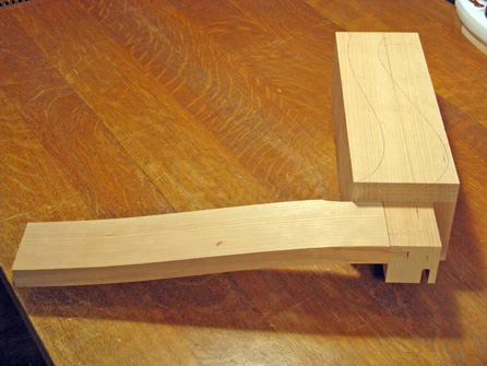
The above shot shows the completed right leg, already glued to the front rail. The glue squeeze-out still has to be removed, and the leg curve blended with the rail curve. I made the inside curve of both the leg and rail such that there was a bit of extra material left at the ends of the curves where they came together. This let me do final shaping after the two pieces were assembled, ensuring a smooth curve between the pieces. The front legs took about 22 hours to complete.
Seat Rails
The plan was to use mortise and tenon joints between the rails and the front legs for strength. At the rear, the rails would instead be dowelled into the rear legs to ensure there was enough rear leg material remaining so that leg strength was not compromised. The biggest question was how to do the side rails. The front of the seat was wider than the rear, so the side rails need to accommodate this difference. I originally had envisioned straight side rails that were angled out, but that makes the ends a bit more complex since the tenons at the front and the pins at the back would need to be at an angle to the rail. After some reconsidering, I decided to change the rails so they were curved. That way, they could contact both the front and the back legs square-on.
After that, the seat rails were pretty straightforward. The side rails were cut out of slightly wider pieces to account for the curvature. The photo on the left below shows the blocks I attached to help keep the wood exactly vertical for cutting. The two side rails with the front tenons cut out are shown below on the right.
After that, the seat rails were pretty straightforward. The side rails were cut out of slightly wider pieces to account for the curvature. The photo on the left below shows the blocks I attached to help keep the wood exactly vertical for cutting. The two side rails with the front tenons cut out are shown below on the right.
As mentioned above, I made sure the rails were fit to the front legs prior to shaping the legs. The left photo below shows one of the side rails in one of the legs. The curved contour of the rail bottom has yet to be cut.
The front rail was even easier than the sides, since it was just flat, and the rear rail was flat, but with a buttress (plinth?) for the back splat, formed with the aid of a table-mounted router. The right-hand photo below shows the rear rail and the two side rails being test-fit, using some proxy rear legs. I had made these little leg sections so that I could use them as a guide to drill the holes in the rails and in the real legs in order to match up the dowel holes. All together, the seat rails took around 12 hours to complete.
The front rail was even easier than the sides, since it was just flat, and the rear rail was flat, but with a buttress (plinth?) for the back splat, formed with the aid of a table-mounted router. The right-hand photo below shows the rear rail and the two side rails being test-fit, using some proxy rear legs. I had made these little leg sections so that I could use them as a guide to drill the holes in the rails and in the real legs in order to match up the dowel holes. All together, the seat rails took around 12 hours to complete.
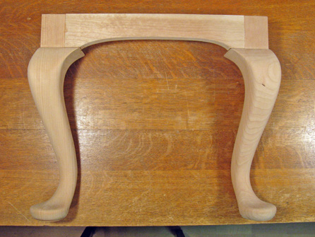
Rear Legs
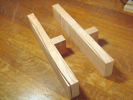
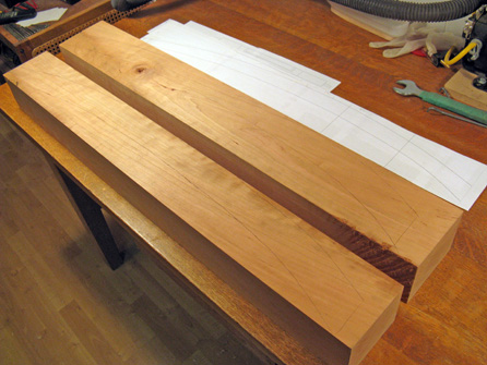
The rear legs were cut out of pretty large stock, but the finished size was no more than 1.5" square. I was concerned about warpage, since the stresses on the wood of the leg could change substantially when the waste was cut away. So instead of cutting the legs close to the finished size, I instead cut them about 0.5" large all around to get rid of most of the excess wood. And then I just let them sit for 2 or 3 months while I worked on other parts (which I guess is an advantage of a long project). That way, if they wanted to warp, there would likely still be enough wood to get to the finished shape that I wanted. The photo on the left below is the two leg blanks, and on the right are the two legs cut out oversized.
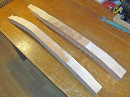
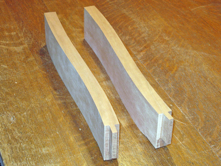
In the end, it didn't look like they warped much, but it's better to be safe than sorry. After their "ageing" period, it was then just a matter of cutting them close to the desired shape and sanding the heck out of them. I used a belt sander to do the outside curves and straight sections. For the inside curves, I used the belt sander with a curved form to give the belt a gentle curve. This got the legs very close to the desired shape. I then used some standard sanding blocks and a couple custom sanding blocks to remove any waviness left by the belt sander (or perhaps more accurately: waviness left by my operation of the belt sander). The photo on the left below (looking like something out of the movie Brazil) shows a leg on the belt sander.
The photo on the right above shows the leg in the middle of hand-sanding. The long baby-blue block on the bench is a straight sanding block I used to flatten out the straight sections of the legs.
The legs were sanded up to 320 grit, which was sufficient to remove any visible scratches. The photo to the right shows a completed leg with the holes drilled for the pins to hold the rear and side rails.
The legs were sanded up to 320 grit, which was sufficient to remove any visible scratches. The photo to the right shows a completed leg with the holes drilled for the pins to hold the rear and side rails.
Assembly
Theoretically, the whole chair could have been assembled all at once in one mad frenzy of gluing and clamping, but since glued joints are pretty tough to disassemble if an error is made, I did the assembly in five steps.
I started the assembly with the front rail and the front legs. The three pieces were glued together at the mortise and tenon joints at the corners. I didn't use any other fasteners since the glue joint alone should be adequate. Doing just these three pieces let me make sure the legs were correctly positioned and vertical with only two glue joints to worry about.
But as it turned out, despite the simple assembly and a dry run, I managed to position something incorrectly in the clamping setup, and the front rail was not correctly seated on the legs. You can see one of the resulting gaps in the left photo below, between the rail and the curved leg section. But of course the real test of a woodworker is how well he* can fix his screw-ups. And let me tell you, I get a lotta practice. The photo on the right shows the same joint after the gap has been filled with home-made filler (glue + sawdust), and after the finish has been applied. I won't bother with a comprehensive recounting of other fixed errors since the web site is limited to 100 MB.
*or she, of course, or perhaps zie, for those woodworkers with an hermaphroditic ...um....configuration.
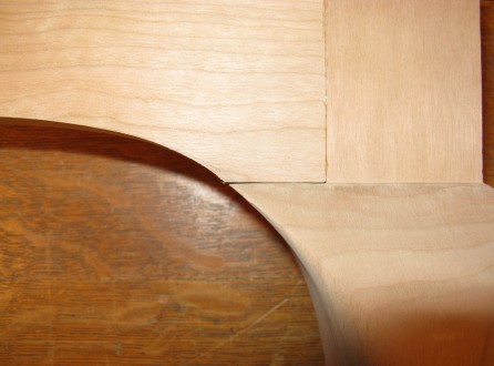
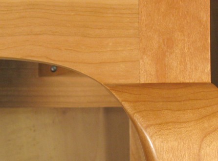
You can also almost see a faint pencil line on the bottom of the curve of the rail in the left photo above This is the desired finished curve. The rail and the leg were sanded together down to this line to produce the more continuous curve that can be seen in the right photo.
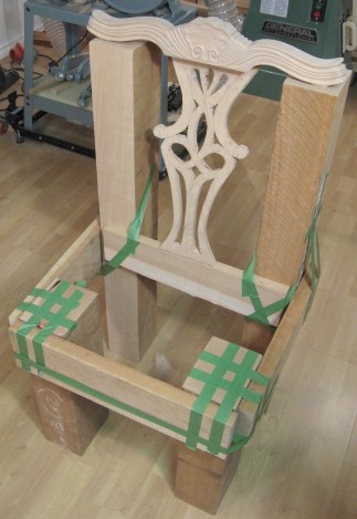
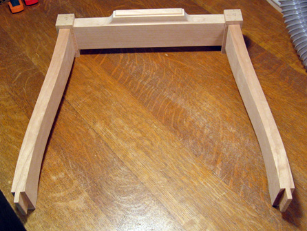
The photo on the left below shows the assembly. The rail can be seen to be a bit above the ends due to my "gluing problem", so it was just planed down to match. The second step was to attach the two side rails. The original three-piece assembly was clamped to the side rails as shown on the shot below on the right. This formed the main section of the frame for the seat, so I wanted to make sure that it would be flat on the top, and square. Clamps held everything tight, flat and at the correct angle. I used the rear rail and proxy legs to make sure the side rails were correctly positioned, and used a wooden spacer (seen going diagonally across the frame with a little yellow clamp on it) to ensure the assembly was square.
The photo on the left below shows the assembly. The rail can be seen to be a bit above the ends due to my "gluing problem", so it was just planed down to match. The second step was to attach the two side rails. The original three-piece assembly was clamped to the side rails as shown on the shot below on the right. This formed the main section of the frame for the seat, so I wanted to make sure that it would be flat on the top, and square. Clamps held everything tight, flat and at the correct angle. I used the rear rail and proxy legs to make sure the side rails were correctly positioned, and used a wooden spacer (seen going diagonally across the frame with a little yellow clamp on it) to ensure the assembly was square.
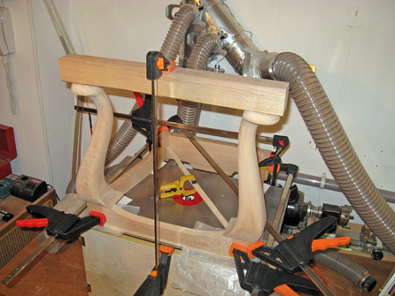
Once this assembly was done, I was able to complete the curve shaping by blending the leg curves into the rail curves as mentioned above, using the spindle sander and hand-sanding.
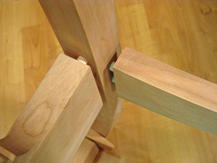
The third step was to assemble the three-sided seat rail assembly made above to the rear legs and rear seat rail. As mentioned previously, the rails connected to the rear legs using pins fitting into blind holes drilled in the rails and the legs.
The third step was to assemble the three-sided seat rail assembly made above to the rear legs and rear seat rail. As mentioned previously, the rails connected to the rear legs using pins fitting into blind holes drilled in the rails and the legs.
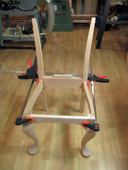
The above photo shows the side and rear rails with pins fitting into the rear leg. To the right is a shot of how the pieces were clamped together for gluing. When they were actually glued, the top rail was put in place and a spacer was used between the rear legs at the bottom make sure that everything was at the right angle.
The clamps shown in the photo are cheapo MasterCraft knockoffs of the original Irwin Quick-Grip brand. The Quick-Grips are great clamps, but they were pretty costly when they first came out. They were useful enough so that it made sense to have a couple around, but generally, the more clamps, the better. The seat frame gluing used seven clamps, and that is not an unusual number. A few years back, buying gas at Canadian Tire sometimes supplied a coupon that permitted one to buy the Mastercraft clamps at about 1/10 the cost of the originals, so I stocked up. And a good thing that I did, since they are not very strong. It is easy to apply a bit too much pressure and snap off the end of the clamp. I only destroyed one making the chair, but I have 3 or 4 headless clamp carcasses kicking around the shop.
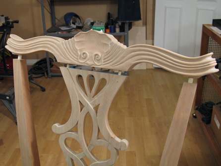
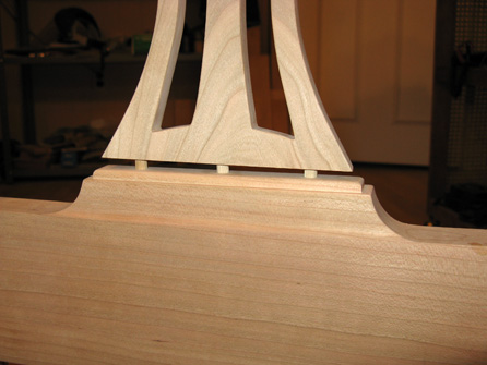
The fourth assembly stage was to add the back and the top rail. Grooved pins were also used for these two parts, as shown in the photos below. As with the other stages, these were glued and clamped.
The fourth assembly stage was to add the back and the top rail. Grooved pins were also used for these two parts, as shown in the photos below. As with the other stages, these were glued and clamped.
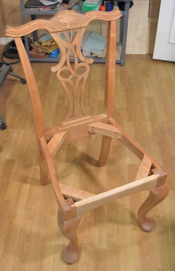
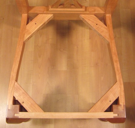
The final assembly stage was to add corner braces to the seat section. The idea was to add strength to the corner joints, and also provide a larger base on which to mount the seat. These parts were unique in that they were glued and screwed to the side rails - the screws are the only non-wood parts in the chair frame (other than glue, of course).
Seat
The seat was a bit of an afterthought. Oh, I knew I needed one, but I hadn't put much thought into exactly how I would make it. I knew I wanted to keep the overall seat height fairly low - it is easy to go 2 or 3 inches high, but I didn't think that would look too good - and I didn't want an odd-looking seat material whose pattern would distract from the woodwork on the chair. To avoid the latter problem, I decided on leather for the covering. That turned out to be a fair amount of work due to the thickness of the leather, but at least it is a timeless sort of covering - no "what was I thinking when I picked that fabric?" issue in a few years.
My original thought was to have the chair seat overlap the edges of the chair a little bit. However, I looked through photos of a number of Chippendale-style chairs and found that without exception, they all had the seat inset from the frame of the chair. So I figured I might as well conform.
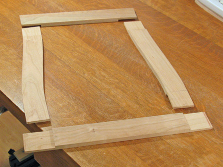
For extra cushioning, I decided to use the frame-and-webbing construction. I started with a frame made from leftover cherry. I wanted it to be as thin as possible, but it needed to be strong enough to handle the forces exerted through the webbing. I used half-lap joints on the corners, with the thought being that these would resist twisting forces (all sides of the frame will be twisted inwards since all the force from the webbing is on the top of the frame). The photo to the right shows the four finished sides of the frame, ready to be joined.
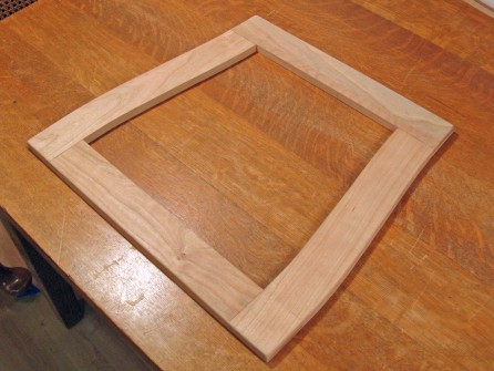
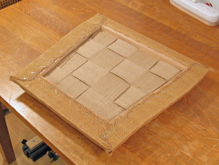
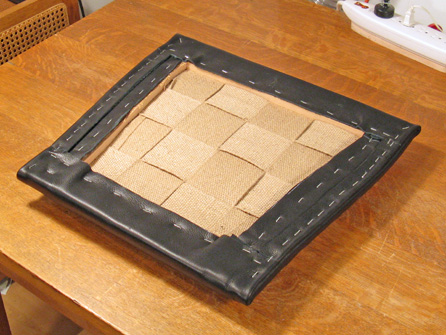
The series of photos below shows the stages in the seat construction. On the lower left, the assembled seat frame is shown. The sides were beveled a few degrees inwards at the top so they wouldn't show through the upholstery. The next stage was to add the webbing. I used a thick jute strip that was woven from adjacent sides to keep it together. It was stretched to be under tension prior to being stapled to the frame.
The series of photos below shows the stages in the seat construction. On the lower left, the assembled seat frame is shown. The sides were beveled a few degrees inwards at the top so they wouldn't show through the upholstery. The next stage was to add the webbing. I used a thick jute strip that was woven from adjacent sides to keep it together. It was stretched to be under tension prior to being stapled to the frame.
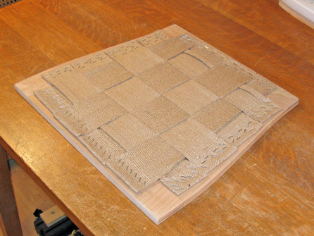
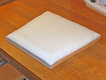
The next two photos show the seat padding. I used high-density foam and cut contours on the edges. However, it turned out that the foam contours easily showed through the leather. To help with that, I added a burlap cover that was stretched over the foam to smooth it out a bit. Burlap seems like a pretty crude material to use in upholstery, but some investigation showed that it is pretty commonly used. I had a bunch in the garage for yard work, so I chopped some off the roll, removed the dead leaves and other plant bits from it, and stapled 'er on.
I had originally thought that a one inch thickness of even high-density foam would not be firm enough, so my first try was to use a softer 2" foam, and pre-compress it down to an inch. I used a thick thread and a longish needle to manually sew through it, first on a 2" grid, and then finer when that didn't work very well. However, even more closely-spaced sewing (and burlap facing on both sides) still left large lumps between the points at which it was sewn. I managed to get the thickness down to maybe 1.5", so that looked like it wasn't going to work, and I went back to the high-density foam approach.
I had originally thought that a one inch thickness of even high-density foam would not be firm enough, so my first try was to use a softer 2" foam, and pre-compress it down to an inch. I used a thick thread and a longish needle to manually sew through it, first on a 2" grid, and then finer when that didn't work very well. However, even more closely-spaced sewing (and burlap facing on both sides) still left large lumps between the points at which it was sewn. I managed to get the thickness down to maybe 1.5", so that looked like it wasn't going to work, and I went back to the high-density foam approach.
Unfortunately, I was able to find only 2" thick foam in the high-density variety, so I ended up starting with that. To get it down to 1" thick, I sharpened up our 10" kitchen knife and sliced my way through. That worked out reasonably well, and I put the sliced, not-quite-flat, side down and left the nice finished side for the top.
The next stage was to cover the seat with the leather, which was straightforward except for the corners. The leather was pretty thick - three layers stacked up to 0.25" - so there was a limit to the number of folds the corner could have if the sides were not to sit way off the chair frame. After a couple hours of trying things out, I finally settled on folding the front and rear around under the seat. This has a fold that is visible from the side and is 3 or 4 layers thick at the corner, but it was better than anything else I could come up with. To compensate for the extra thickness at the corners, I did a couple things. First, I added two layers of leather on the front and rear edges of the seat under the leather cover to thicken up the middle portions so they were similar to the thicker corners. And then on the sides, I added a similar two layers of leather (folded to show a round edge), but on top of the leather cover. These pieces also extended the fold that started at the corner, giving it an "I did this on purpose" look.
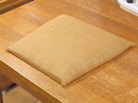
The shots below show the bottom side of the seat with just the burlap covering, and then with the full leather covering applied.
The next stage was to cover the seat with the leather, which was straightforward except for the corners. The leather was pretty thick - three layers stacked up to 0.25" - so there was a limit to the number of folds the corner could have if the sides were not to sit way off the chair frame. After a couple hours of trying things out, I finally settled on folding the front and rear around under the seat. This has a fold that is visible from the side and is 3 or 4 layers thick at the corner, but it was better than anything else I could come up with. To compensate for the extra thickness at the corners, I did a couple things. First, I added two layers of leather on the front and rear edges of the seat under the leather cover to thicken up the middle portions so they were similar to the thicker corners. And then on the sides, I added a similar two layers of leather (folded to show a round edge), but on top of the leather cover. These pieces also extended the fold that started at the corner, giving it an "I did this on purpose" look.
The shots below show the bottom side of the seat with just the burlap covering, and then with the full leather covering applied.
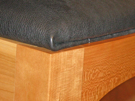
A close-up of the corner below shows how the leather is folded on the side. The final stage was to add a dust cover to the bottom. A common cover material is cotton (muslin), and another is landscape cloth. Since I already had some landscape cloth, it was back out to the garage. I chopped a length off the roll, and then washed the mud out of it - I apparently used for some temporary yard project - then I cut it to size, and stapled 'er on. I also had some old hose out in the garage too, but I couldn't think of any good way to work that into the seat.

The seat was attached to the chair frame with screws through the corner braces. The finished seat looks a bit irregular due to my imperfect upholstering skills, but it has been pointed out that that makes it look more like an antique, so I'm gonna go with that. Making the seat took around 10 hours.
The User Experience
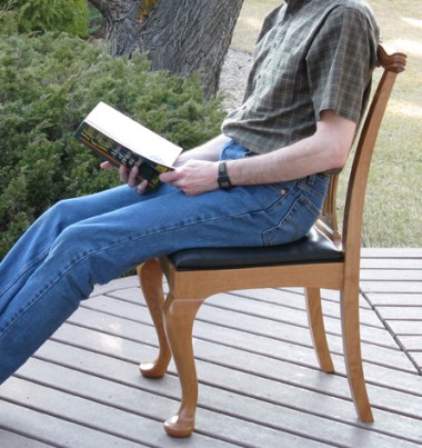
Well, the comfort of the chair is actually not too bad, in a dining-room-wooden-chair kind of way. The seat is pretty firm, and the back does not interfere with the spine too much. That's probably about as good as one can expect comfort-wise from this type of design.
Leftovers