Note: This is a rather long page so I've provided links to the various "chapters";
1. Design
2. Pieces
3. Base
4. Drawer Fronts
5. Top
6. Case Assembly
7. Drawers
8. Final Assembly
1. Design
2. Pieces
3. Base
4. Drawer Fronts
5. Top
6. Case Assembly
7. Drawers
8. Final Assembly
Details
Just before starting this drawer set I had read a Fine Woodworking magazine article - yes, there are still magazines, mostly bought by old people - that described the traditional cabinet-drawer-making procedure. This involved dovetail joints holding pine sides to the hardwood front, with a pine bottom fitted into slotted sides and maple skids on the bottom for less wear.
However there's no real need for dovetail joints unless you like making them (I don't) or plan to show them off to your woodworking cronies (not enough cronies). And there are much better solutions than a tight-fitting rectangular drawer in a rectangular hole sliding on wood. Like side-mounted slides, for example. Then you don't need to be careful to pull the drawer out straight, plus you can pull it out all the way without it falling out. And pine is historically used for the drawer since it is a fairly stable wood - but of course not as stable or indeed hard, strong or straight as the plywood I planned to use. So this drawer set isn't going to generate any magazine articles but it should be convenient and robust.
However there's no real need for dovetail joints unless you like making them (I don't) or plan to show them off to your woodworking cronies (not enough cronies). And there are much better solutions than a tight-fitting rectangular drawer in a rectangular hole sliding on wood. Like side-mounted slides, for example. Then you don't need to be careful to pull the drawer out straight, plus you can pull it out all the way without it falling out. And pine is historically used for the drawer since it is a fairly stable wood - but of course not as stable or indeed hard, strong or straight as the plywood I planned to use. So this drawer set isn't going to generate any magazine articles but it should be convenient and robust.
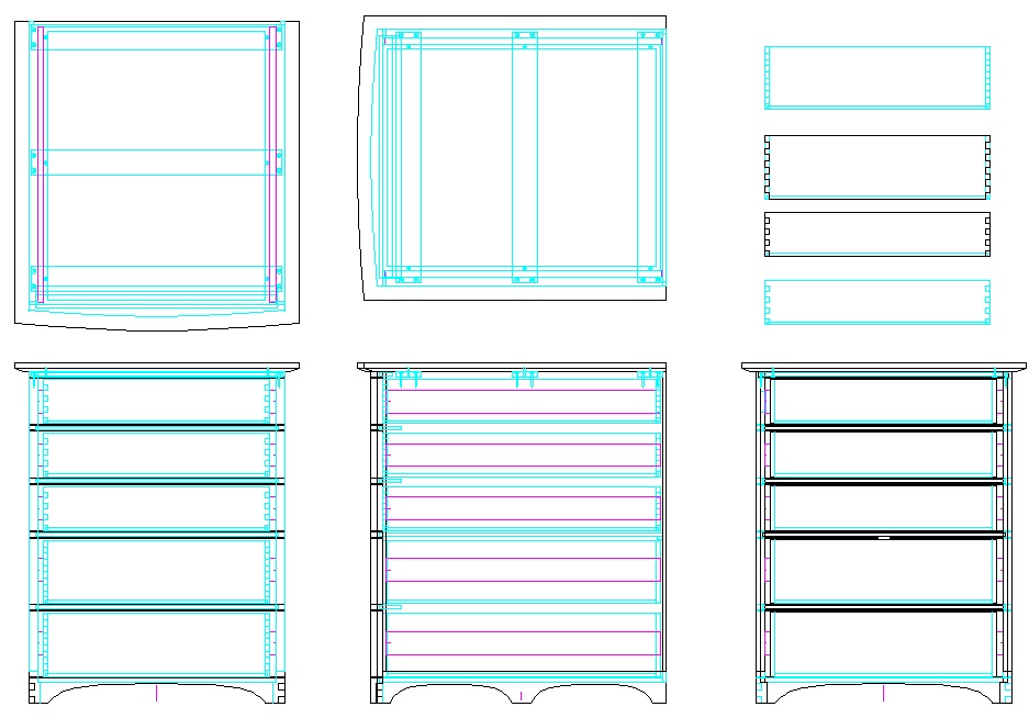
The 2D plan
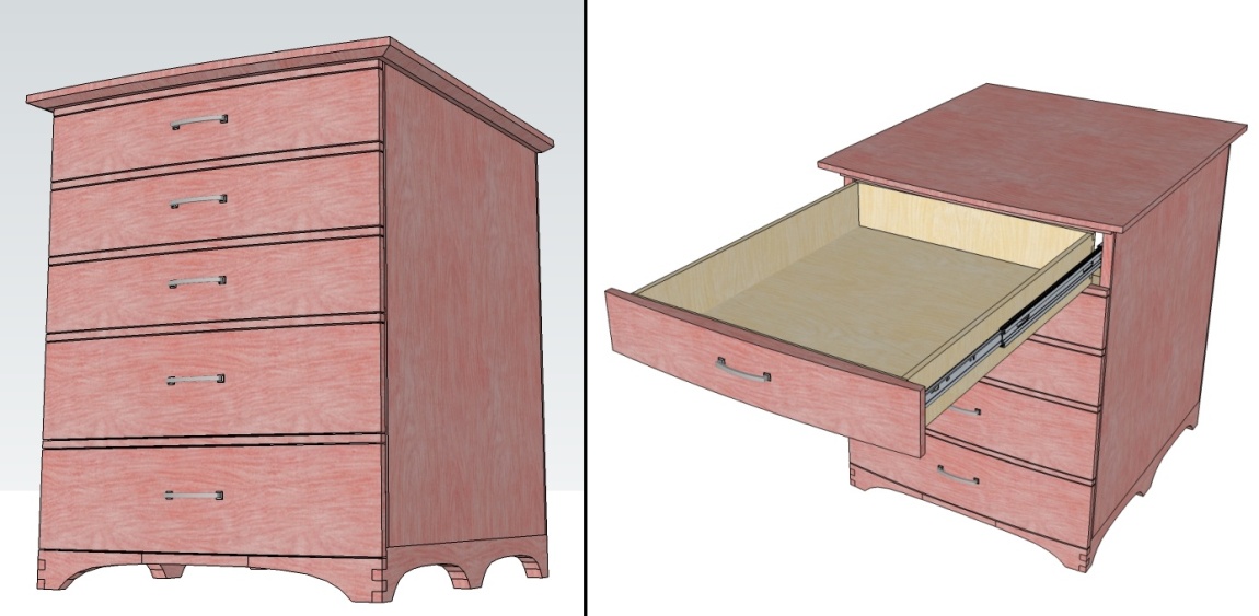
The 3D view in a not-very-convincing Cherryish color
Design
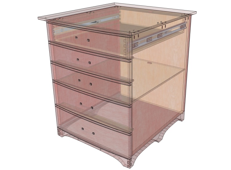
An X-ray view with only the top drawer in place
I wanted to make the drawer set look decent but was trying to avoid anything too fancy; it will be sitting in a closet after all.
I opted for a short base with curved feet to hold it up out of the carpet, then a small-overhang solid top with a bottom-side bevel. The drawer fronts and top will have a slightly rounded profile with drawer fronts flush with the sides.
The drawer bodies would be 3/8" plywood mounted to the case with full-extension slides.
Producing Pieces Out Of Planks And Plywood

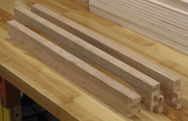
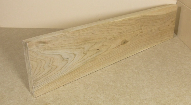
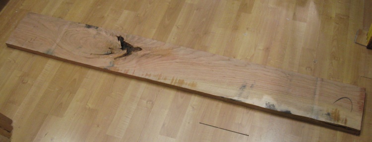
A fair pile of disreputable-looking cherry
The only retail source of hardwood in Saskatoon is Windsor Plywood so one is at the mercy of their stocking levels. In this particularly merciless instance they had no cherry in the thickness I needed and only a couple thicker pieces that were too knotted and cracked to be useful.
But they also had cherry "shorts" which were generally bad pieces, but shorter and fortunately cheaper. I was able to find enough of those to be able to get all the pieces I needed from the good sections.
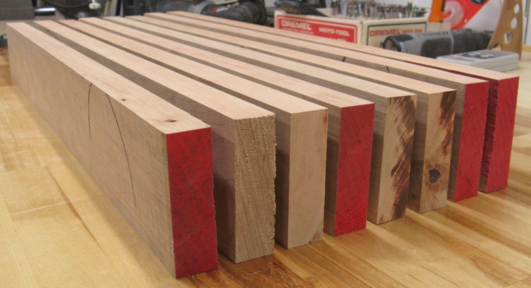
This shot shows the five planks I used.
But they also had cherry "shorts" which were generally bad pieces, but shorter and fortunately cheaper. I was able to find enough of those to be able to get all the pieces I needed from the good sections.
This shot shows the five planks I used.
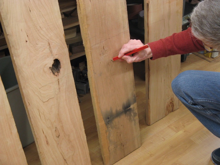
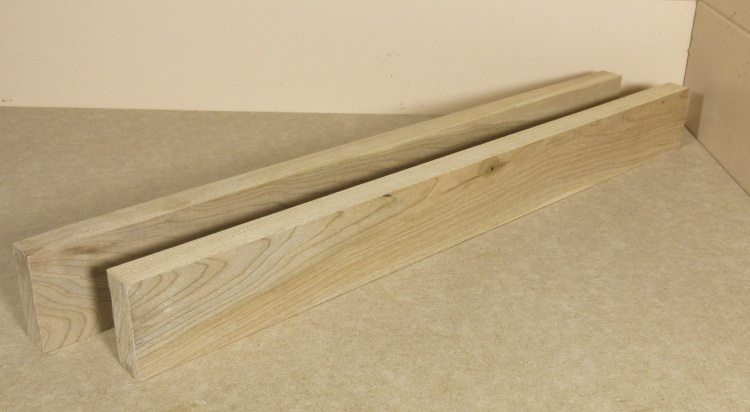
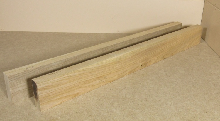
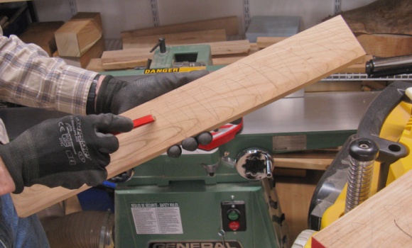
Mapping the planks into pieces
I spent some time mapping out which pieces would come out of which plank. They were already slightly thinner than what I needed so surface roughness was a problem, not to mention cracks and knots.
But ultimately I was able to get what I needed with essentially no leftovers except for scraps too short to be useful for these drawers.
But ultimately I was able to get what I needed with essentially no leftovers except for scraps too short to be useful for these drawers.
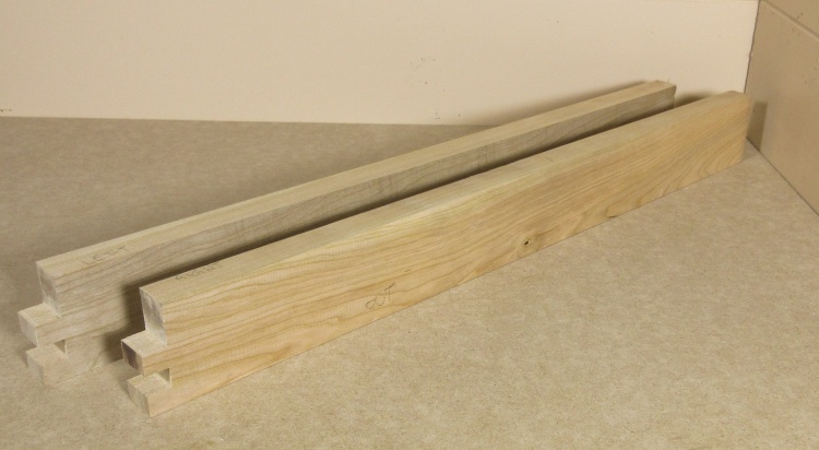
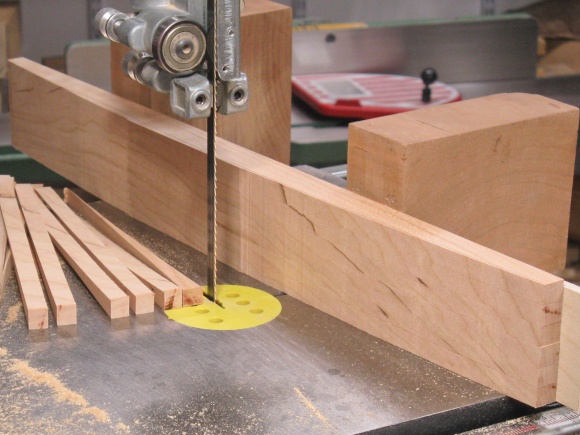
Then it was a matter of cutting the planks into the proper-sized pieces. I used my normal cut-it-up tag-team of radial arm saw and bandsaw.
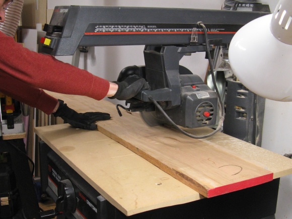
Starting to chop the pieces to length on the RAS
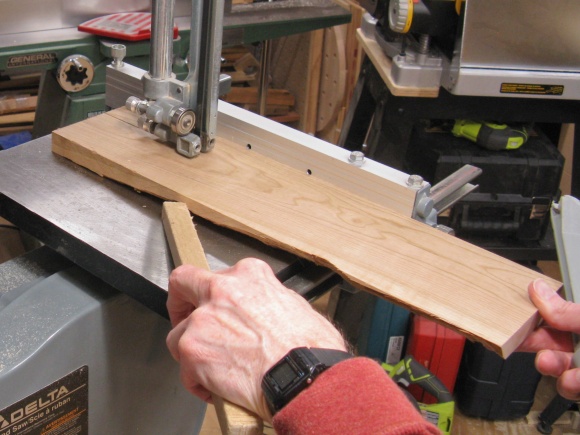
Further slicing with the BS
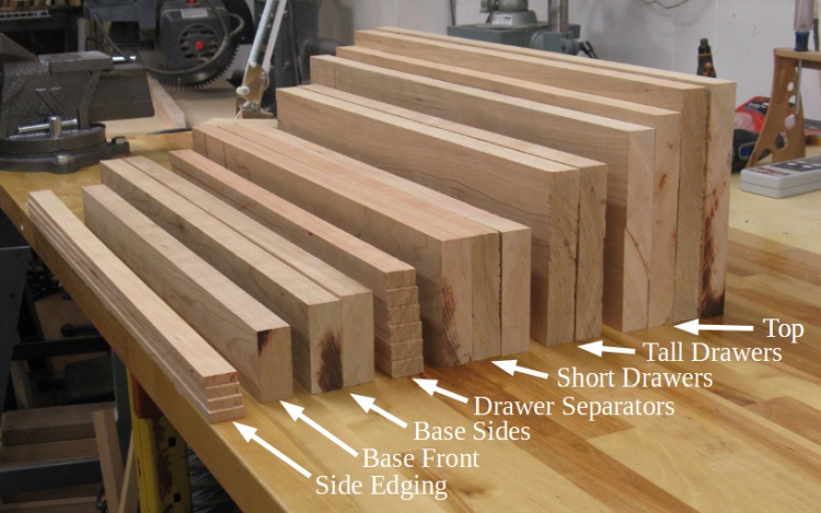
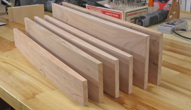
The full set of cherry pieces
It didn't take too long to turn the planks into pieces. Sawing efforts produced the group in this annotated photo which includes all the cherry pieces needed for the drawers.
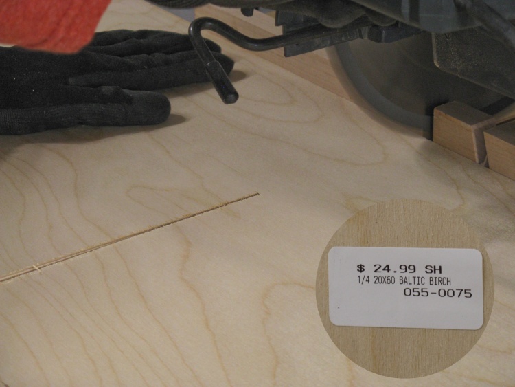
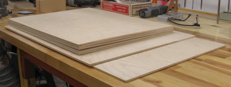
The plywood supply
The drawer set also used plywood for drawer bodies and parts of the case.
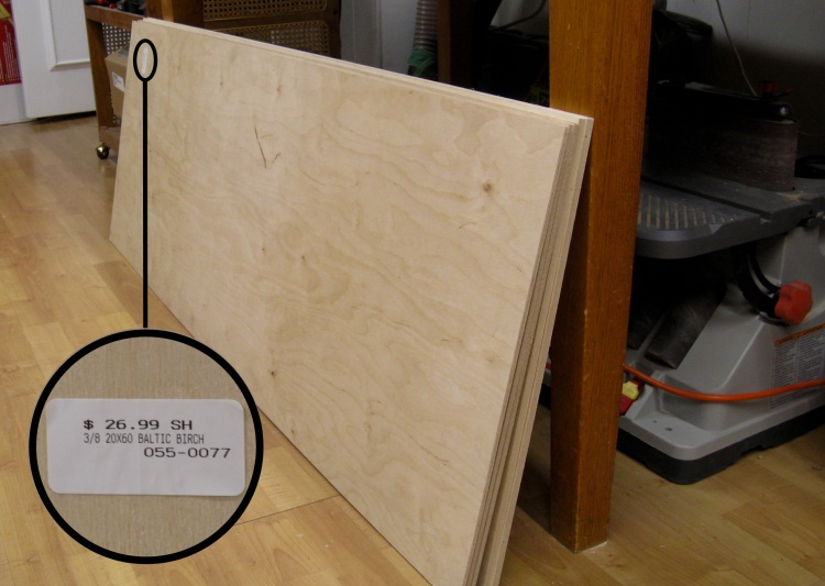
This shot shows the small stack of 1/3-sheets (20" x 60") of 1/4" and 3/8" thickness Baltic birch plywood.
This shot shows the small stack of 1/3-sheets (20" x 60") of 1/4" and 3/8" thickness Baltic birch plywood.

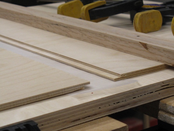
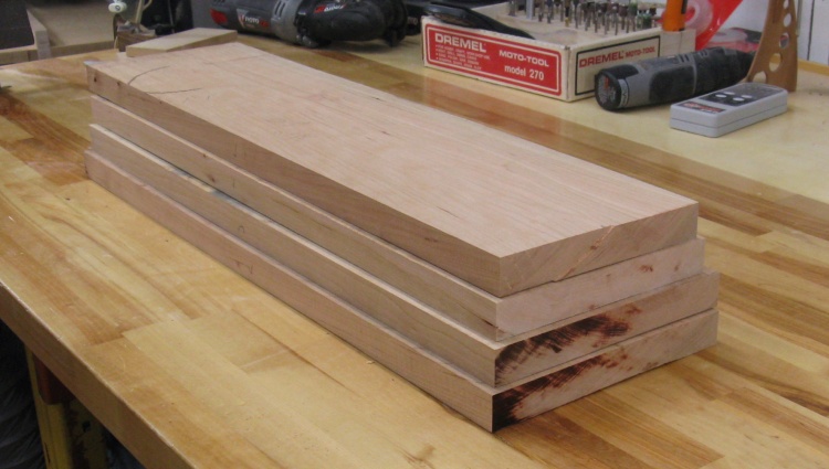
3/8" plywood chopped into drawer-sized pieces
The 3/8" plywood was used for the drawer sides and this photo shows the complete set after cutting to size.
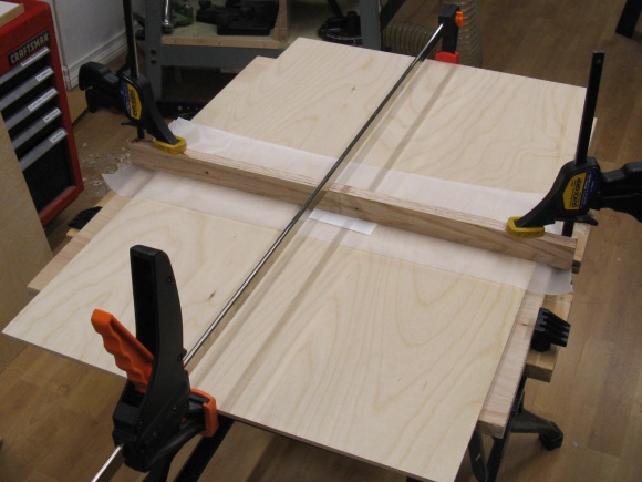
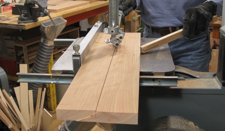
1/4" plywood getting cut to length on the RAS

The 1/4" plywood bits
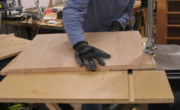
The 1/4" plywood was used for a few parts as shown above.
This shot shows a piece too wide being cut on the RAS. I've made one cut as long as possible then flipped the plywood over to cut from the other side.
This shot shows a piece too wide being cut on the RAS. I've made one cut as long as possible then flipped the plywood over to cut from the other side.
I was left with a number of too-small-for-the-drawer-set scraps so I decided to join a couple of those to avoid having to get hold of another sheet of plywood. These two pieces are being joined with a simple router-cut lap joint. The resulting piece will be used as an internal divider in the case so the look of the joint won't really matter.
Lap joints on a couple smaller pieces
Gluing them into a more useful size
The spring collection of 1/4" plywood pieces
This shot shows most of the 1/4"-thick plywood pieces the drawer set will use.
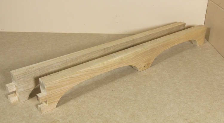
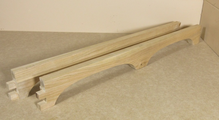
Base
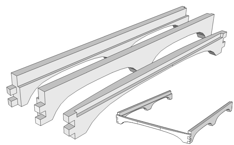
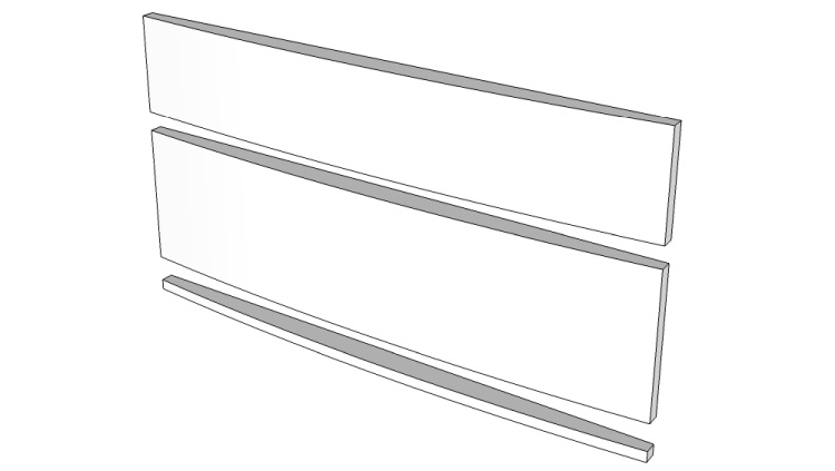
The three base pieces (before being woodified)
After everything was cut up, I thought I'd start out by making the base.
This diagram shows what the three pieces of the base will need to end up looking like.
The pieces include a curved front and two mirror-image sides with 1/2" box joints used to join the pieces at the front corners.
This diagram shows what the three pieces of the base will need to end up looking like.
The pieces include a curved front and two mirror-image sides with 1/2" box joints used to join the pieces at the front corners.
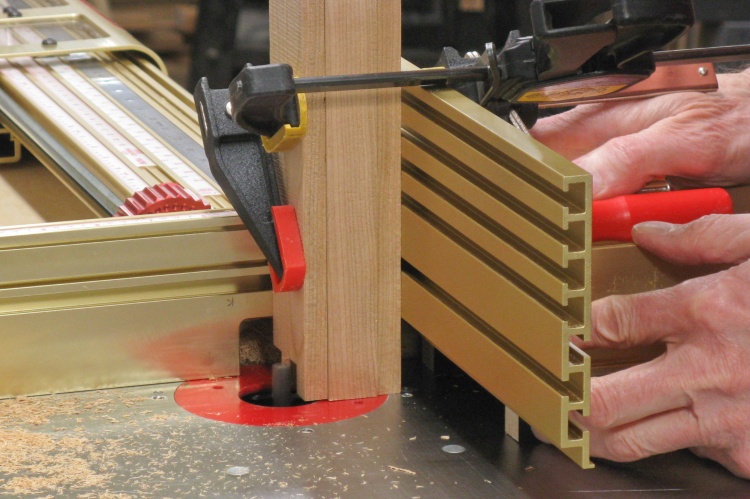
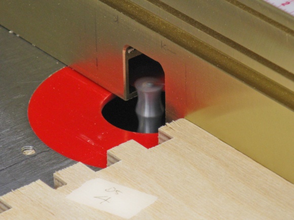
Cutting corner box joints on router table
One of the first things I did was to cut the box joints for the corners. I started with a test piece to get exact jig settings and in this shot I'm part way through one of the ends of the front piece.
I originally tried a 1/2" bit for the 1/2" box joints but that didn't produce a clean joint. Results were better when I switched to using a 3/8" bit and made multiple cuts to get the 1/2" gap.
I originally tried a 1/2" bit for the 1/2" box joints but that didn't produce a clean joint. Results were better when I switched to using a 3/8" bit and made multiple cuts to get the 1/2" gap.
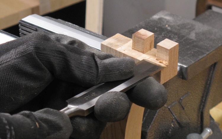
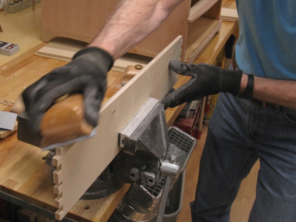
Cleaning up the joints on the right side piece
The joints were cut through the full thickness of the side but they ultimately needed to span just over half the width.
To narrow them down, they were trimmed with the bandsaw and this photo shows me cleaning up an end after that operation.
To narrow them down, they were trimmed with the bandsaw and this photo shows me cleaning up an end after that operation.
The curved profile of the base piece's "feet" was traced on the wood, cut with the bandsaw and then sanded smooth. In these shots I'm working on the two sides which have been taped together so they can be done at the same time.
Cutting side profiles

Cleaning up the curve
Base pieces partly done
This photo is an interim shot with the joints formed and the base curves cut. But as I would say if I was a character out of a Western, they ain't done yet.
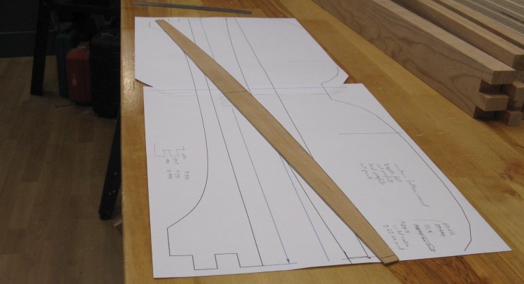
A thin wooden pattern for the front curve
I was going to need to mark the front base piece with the appropriate curve and then cut it out. And I'd eventually need to do that for another ten pieces so with that much repetition I figured a pattern I could trace would be come in handy.
For that I sliced off a piece of cherry to about 0.06" thick and then marked, cut and sanded it to the proper curve.
In this shot it sits on the full-sized paper plan used to trace out the curve.
For that I sliced off a piece of cherry to about 0.06" thick and then marked, cut and sanded it to the proper curve.
In this shot it sits on the full-sized paper plan used to trace out the curve.
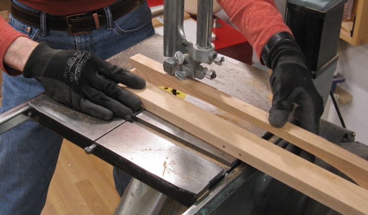
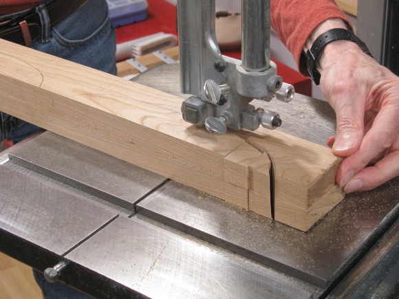
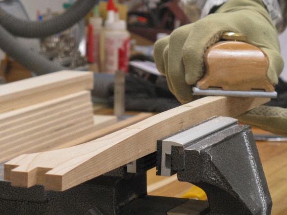
Cutting the curve into the front base piece
I traced the curve on to the front base piece using the pattern and then taped on a small plank to keep it vertical.
In this shot I'm doing the curve cutting on the bandsaw.
In this shot I'm doing the curve cutting on the bandsaw.
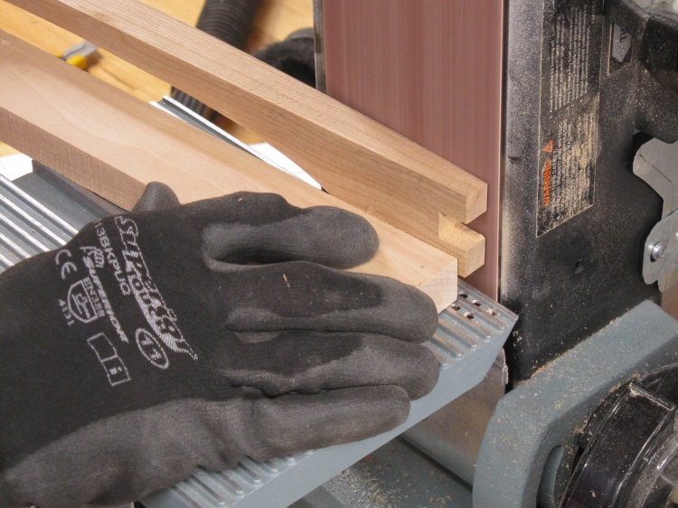
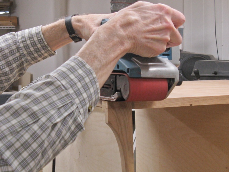
Smoothing the curve on the belt sander
I left the plank in place to keep the piece vertical and moved over to the belt sander to smooth my somewhat wobbly bandsaw cut to get the shape closer to the marked-on line.
The belt sander worked great to smooth the curve but the cost was 120-grit scratches across the grain. Those needed to go, so they were hand-sanded off using a sequence of 150, 220 and finally 320 grit sandpaper. After the surface reached an "ooh, feels smooth" state I also rounded the front corners to about a 1/4" radius and sanded those smooth as well.
Then getting rid of the belt sander marks
...and rounding the outside corner
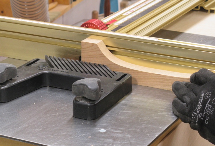
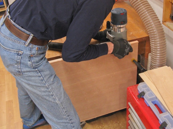
A base piece getting some profiling on the router
The side base pieces would receive the same corner-rounding attention as the front but first all the pieces had various necessary slots routed into them like the right side piece in this photo.
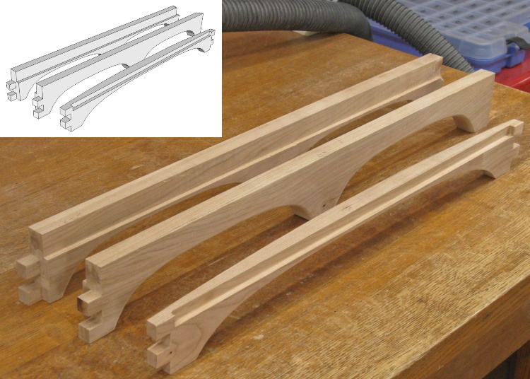
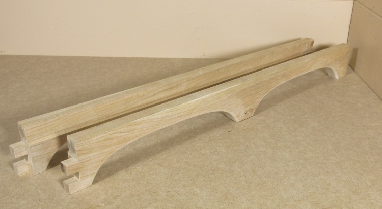
Base pieces (almost) complete
This photo shows the completed base pieces posed just like their digital doppelgängers.


This image lets you step through the operations performed to fabricate the two base sides. Click the arrows to progress through.
This sequence includes a bonus cut-the-biscuit-slot stage not yet done in the previous photo.
This sequence includes a bonus cut-the-biscuit-slot stage not yet done in the previous photo.
Drawer Fronts
The three varieties of front pieces needed
The drawer fronts are purely decorative and get attached to the front wall of the drawer body.
The fronts were pretty simple; each was just an appropriately-sized rectangle with a slightly rounded face.
This sketch shows the three varieties needed;
- three of the short drawers,
- two of the tall drawers and
- five of the drawer separators.
The fronts were pretty simple; each was just an appropriately-sized rectangle with a slightly rounded face.
This sketch shows the three varieties needed;
- three of the short drawers,
- two of the tall drawers and
- five of the drawer separators.
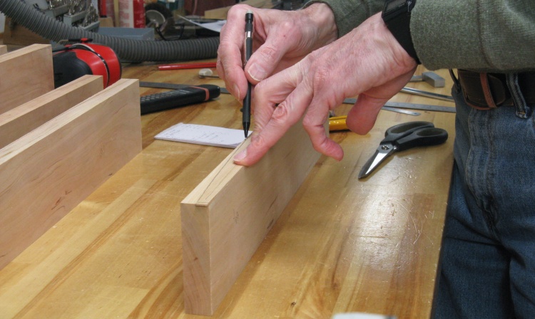
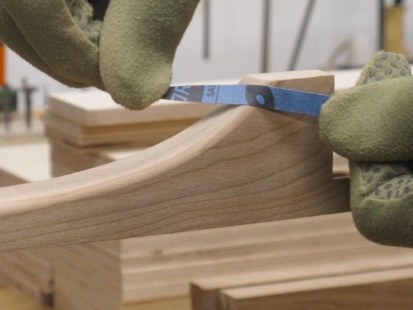
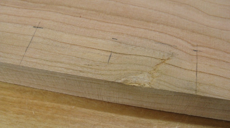
Marking the curve on a short drawer front
After finding the thinnest front (they varied a bit depending on the original plank used), I adjusted the wooden pattern to fit that thickness.
I then traced out the pattern with a pencil to mark the shape on one edge of the front.
To ensure the front was symmetrical side-to-side, I used only half the pattern. I traced half of the curve on the first end of the front and then flipped the pattern end-for-end and used the same half of the pattern to trace the second end.
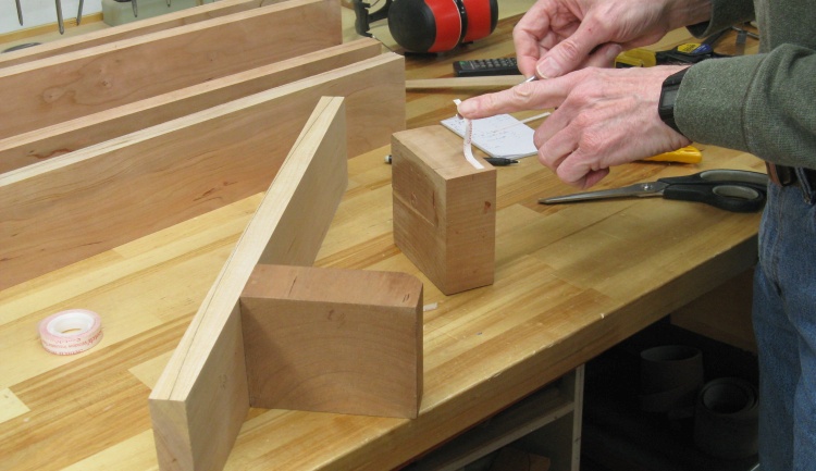
Taping on a couple handles
For more-convenient handling of each front, I taped a pair of square blocks onto the back which kept the piece vertical and gave me something to hold while sawing and sanding.
In this not-at-all-staged photo I'm pulling off the double-sided tape backing for the second block.
In this not-at-all-staged photo I'm pulling off the double-sided tape backing for the second block.
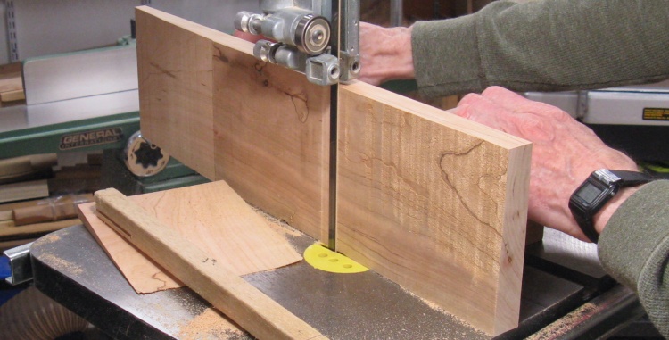
Cutting the curve on the bandsaw
After ensuring the bandsaw table was square to the blade, I cut the fronts just outside the marked line.
The center portion of the fronts didn't usually get cut since the line was too close to the edge.
The center portion of the fronts didn't usually get cut since the line was too close to the edge.
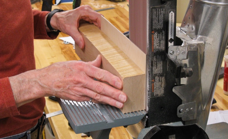
Cleaning up the curve
I left the blocks in place and moved over to the belt sander to round off the saw cut. The 120 grit belt cut fairly slowly but that gave me good control of the shaping.
Sanding off the cross-grain scratches left by the belt sander
As with the base front, the next step after removing the blocks was to sand out the scratches left by the belt sander. I also sanded the four edges while I was at it, going up to 320 grit.
There are 0.4"-thick dividers between the drawer fronts and the set needed five of them. Rather than shape those individually, I taped all the blanks (plus a spare) to a piece of 1/4" plywood and did the cutting and sanding with them all together.
Inter-drawer pieces stacked for cutting
Curve cut
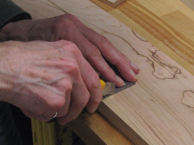
A bad spot on one of the tall drawer fronts
One of the tall drawer fronts had the edge of a knot including a shallow crack right in the middle. The back of this piece was even worse so I couldn't just flip it around. Since I didn't have any extra cherry to make another front, I thought I'd see how a repair would look.
This photo shows the bad spot with the pencil outline showing the extent of a patch to cover it up.
This photo shows the bad spot with the pencil outline showing the extent of a patch to cover it up.
I cut out the rectangular area with a utility knife and then chiseled out the edges and most of the center portion. To keep the floor of the patch area flat I used a Dremel to route the floor about 0.05" below the surrounding area. I then cut a tight-fitting patch from a scrap piece of cherry and glued that into place.
Slicing around the area
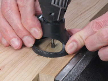
Dremel-routing for a flat bottom
New piece glued in and well clamped
Fix looks decent after sanding
After the glue was dry, the patch was sanded flush with the surface.
It actually looks fairly decent but while trimming the edge of the patch flush I fumbled the board on the jointer and gouged out a corner. Sigh. One patch - maybe OK. Two patches...no.
It actually looks fairly decent but while trimming the edge of the patch flush I fumbled the board on the jointer and gouged out a corner. Sigh. One patch - maybe OK. Two patches...no.
Russ bows to the inevitable and gets another crappy piece of cherry
So then it was back to the North end to Windsor for another piece of cherry (and this was one of the better ones).
So I cut out a new front, trimmed to size, jointed it flat, cut the curve and sanded it smooth.
So I cut out a new front, trimmed to size, jointed it flat, cut the curve and sanded it smooth.
Drawer fronts and separators done
This shows the five completed drawer fronts along with the between-drawer pieces which form the stack on the left.
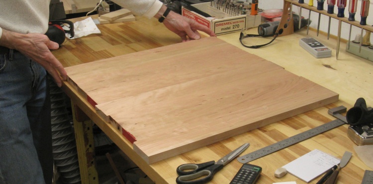
Top
Stack of pieces for the top
These four pieces would form the top of the drawer set. The total width was a bit more than was needed so I decided to cut them into narrower pieces of more consistent width since I thought that might look better.
Cutting into more-uniform widths
Cutting to width was done on the bandsaw.
The raw top pieces ready for next steps
That resulted in these eight almost-consistent-width pieces. A couple were 0.1" narrower than needed so another couple were made 0.1" wider to compensate.
Then it was over to the jointer to flatten faces and edges. I started by flattening one of the wide faces on each piece. In the first shot I'm scribbling on the surface with a construction pencil so it will be obvious which areas still need flattening. After that I jointed the edges to make them straight and square - necessities for tight joints.
Marking up a face
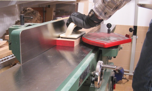
Flattening that face
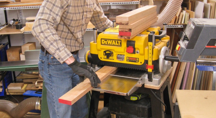
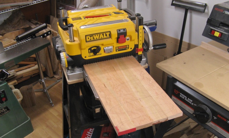
Planing to a uniform thickness
The next step was to plane the pieces to a consistent thickness. With the newly flattened faces down, this also removed any thickness variation in the boards.
The planer seemed to be in a good mood and wasn't doing any obvious snipe, but it isn't a big problem on a top like this one anyway as it can easily be sanded out.
The planer seemed to be in a good mood and wasn't doing any obvious snipe, but it isn't a big problem on a top like this one anyway as it can easily be sanded out.
Finding a good sequence for the planks
I spent a bit time finding the best sequence of boards, matching colors and making sure the edge joints would be gap-free.
Then it was time to start laminating the top. There were a couple advantages to doing it in two stages; 1. It would be much easier to glue and align four pieces rather than eight and 2. Then each half would still be narrow enough to go through the planer to have any height misalignments removed.
I worked on the Workmate with a flat board on top which let me get clamps in convenient spots. I also set the planks on some consistent-height square pieces which let the clamps be better centered on the planks. Cauls were clamped at the ends to help ensure the pieces were vertically aligned.
I worked on the Workmate with a flat board on top which let me get clamps in convenient spots. I also set the planks on some consistent-height square pieces which let the clamps be better centered on the planks. Cauls were clamped at the ends to help ensure the pieces were vertically aligned.
Applying glue for the first half
The first four planks glued together
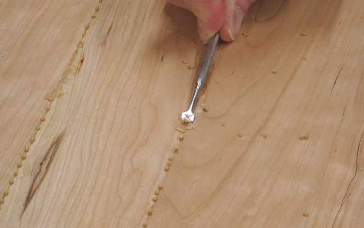
Scraping off the squeeze-out
I made sure to use a generous amount of glue, as is evident by the half-dried squeeze-out on the bottom.
In this shot I'm using a modified dental tool to scrape off the glue drops.
In this shot I'm using a modified dental tool to scrape off the glue drops.
Planing first half smooth
And as promised the half-top was put through the planer to even-up the faces and remove any remaining glue.
The top side got the (barely-visible) pencil scribbles so I could tell when all areas had been planed.
The top side got the (barely-visible) pencil scribbles so I could tell when all areas had been planed.
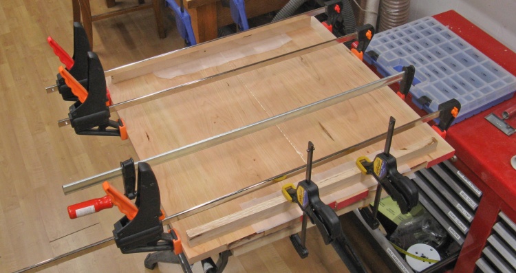
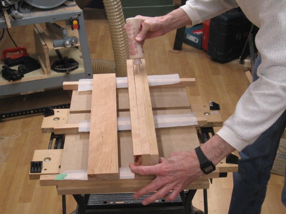
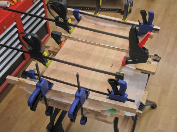
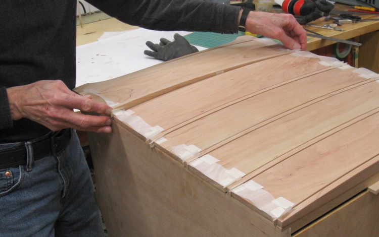
Putting the two halves together
The second half was made in the same manner and then the two were glued together as shown here.
The boards used for the top were made a bit long so they could be trimmed after assembly. That was done with the radial arm saw although it needed two cuts to get through the full length of the sides. Following that the front edge was marked by tracing a paper pattern and then cut into a curve on the bandsaw.
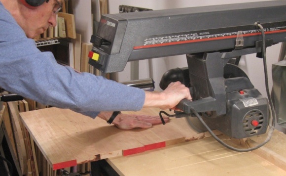
Trimming the edges
Rounding the front
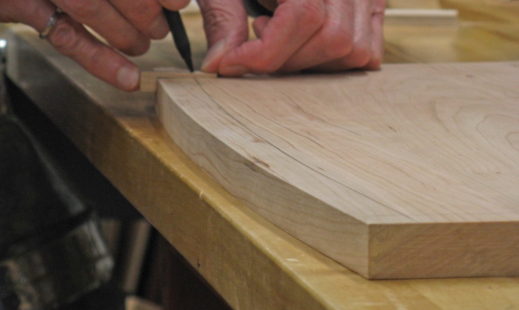
Marking the bevel
After some sanding on the front edge to smooth out the curve, the top was ready to be marked for the bottom bevel.
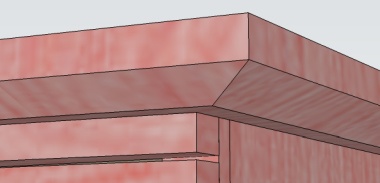
The bottom bevel
The bottom side (which in this photo is the upper face) and the edges were marked using a jig to run lines parallel to the corners as a guide to the bevelling operation.
This type of bevel would be a bit tricky to cut with power tools so rather than arrange some special jig to let me do that, I decided to just cut it by hand.
The worst part was actually sharpening the hand tools, especially the plane which had a few nicks in the blade so it needed a fair amount of metal removed. But once that was done it went relatively smoothly;
I started by using the draw knife to cut off the bulk of the corner, then switched to the spokeshave which was set for a fairly heavy cut (~0.01"). Finally when the bevel was close I finished off with my little block plane set for lighter cuts (about 0.003"). I'm not sure I'd be completely satisfied with the resulting bevel if it was exposed but my less-than-perfect smoothness would be fine on the underside of the top.
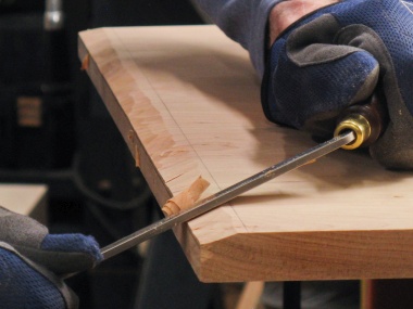
Coarse cuts with draw knife
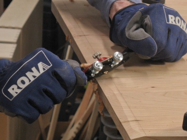
Medium cuts with spokeshave
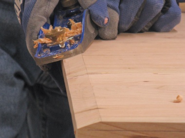
Finer cuts with block plane
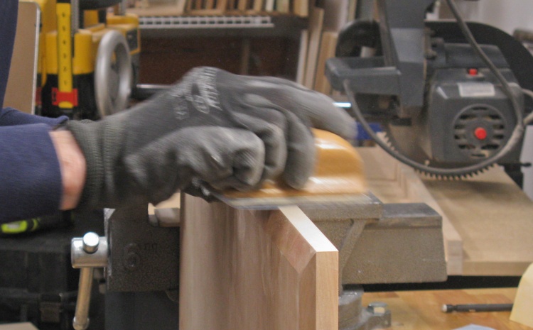
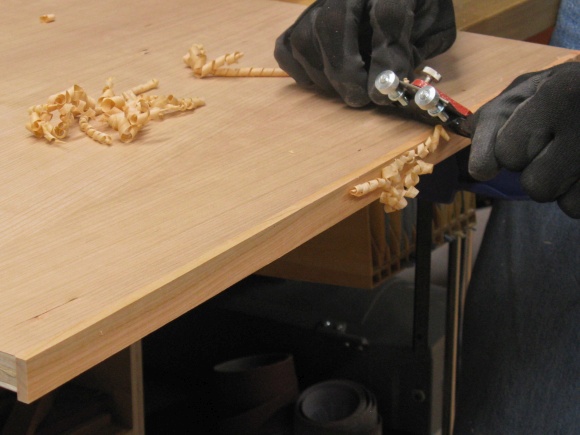
Smoothing out the end-grain sides
The last bit of work on the top was of course sanding. The random orbital sander was used on the faces and then I hand-sanded the edges to a no-scratches-visible state as in this shot.
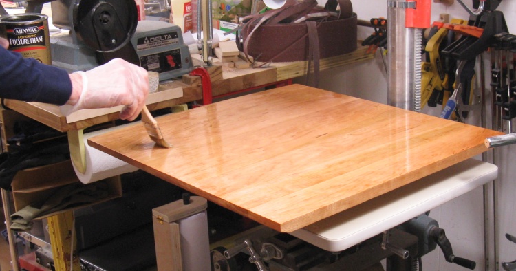
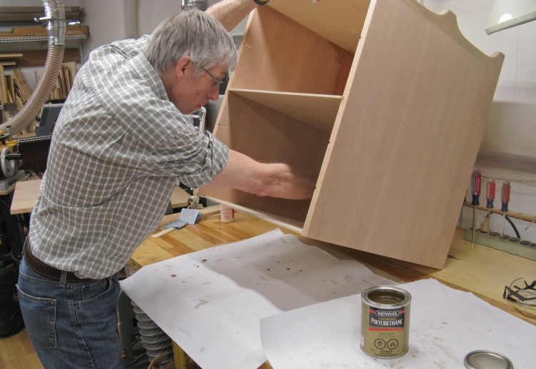
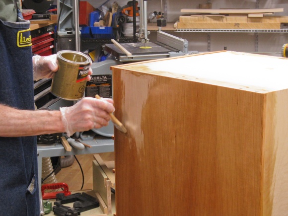
The first coat of varnish going on to the completed top
And then the top was ready for finishing, with this photo showing the first coat of varnish being applied.
I employed a bristle brush for this first coat since it can hold more finish than a foam brush. Then for a smoother finish I switched to cloth-wrapped foam brushes for the second and third coats. As usual the surfaces were sanded with 220 grit between coats.
I employed a bristle brush for this first coat since it can hold more finish than a foam brush. Then for a smoother finish I switched to cloth-wrapped foam brushes for the second and third coats. As usual the surfaces were sanded with 220 grit between coats.
Case Assembly
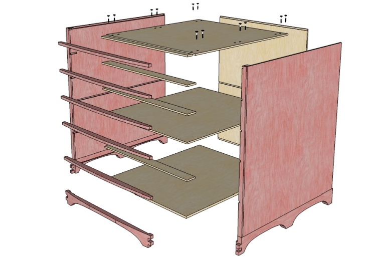
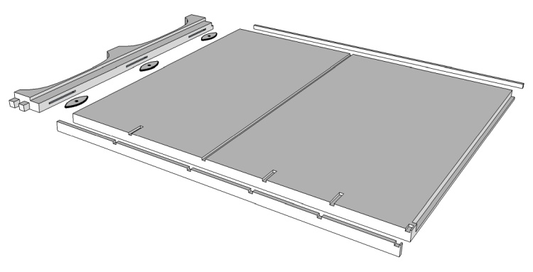
Exploded view of the case (less top)
The case is composed of two side assemblies connected at bottom, middle and top. This somewhat cluttered exploded view shows all the parts.
It is all held together with glue except for the internal top panel, which gets supplemental screws.
It is all held together with glue except for the internal top panel, which gets supplemental screws.
The right side assembly
Each of the side assemblies is composed of cherry plywood mounted on a solid cherry base with solid edging applied to front and back edges.
This uncolored diagram shows an exploded view of a side assembly with the base at its bottom edge and trim on front and back edges.
This uncolored diagram shows an exploded view of a side assembly with the base at its bottom edge and trim on front and back edges.

A 2' x 4' sheet of cherry plywood
I had cleverly planned to be able to use a single quarter-sheet of cherry plywood for the sides of the case although I feared I'd need to buy a whole 4' x 8' sheet of plywood and leave 3/4 of it unused. But fortunately I was saved by Windsor Plywood's iffy stocking - they didn't have any.
I didn't want to have to apply veneer to plywood (which was a last-ditch option) so in desperation, I searched for other sources of cherry plywood. Much to my surprise Home Depot came through and even sold quarter-sheets - exactly what I needed. I ordered one (available on-line only) and it arrived in a week or so while I worked on other parts of the drawer set. This is the quarter-sheet leaning up against the table.
I didn't want to have to apply veneer to plywood (which was a last-ditch option) so in desperation, I searched for other sources of cherry plywood. Much to my surprise Home Depot came through and even sold quarter-sheets - exactly what I needed. I ordered one (available on-line only) and it arrived in a week or so while I worked on other parts of the drawer set. This is the quarter-sheet leaning up against the table.
I needed pretty much the whole quarter-sheet. It got cut into two pieces, trimmed to width and then the exact size was tweaked by using the jointer (which was set to take about 0.015" off per pass).
Chopping the plywood to size
...and tweaking dimensions with jointer
The front facing wood glued on
Of course when you use regular plywood, you need to "deal with the edges". That usually involves attaching some solid-wood edging to cover up the unsightly wood plys visible on the edges.
And that's just what I did here by gluing on a 1/4"-thick piece of cherry to the front edge. The cherry was cut oversized so I could later trim it flush.
A similar but narrower piece of cherry went on the back edge.
And that's just what I did here by gluing on a 1/4"-thick piece of cherry to the front edge. The cherry was cut oversized so I could later trim it flush.
A similar but narrower piece of cherry went on the back edge.
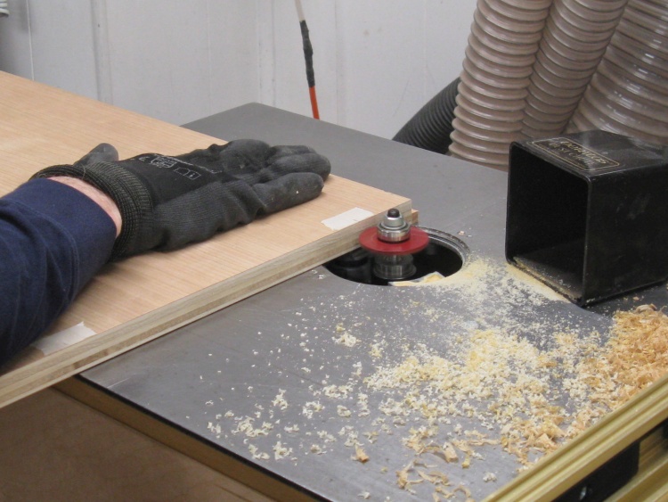
So then there's the "trim it flush" part. I was able to use a flush-cutting bit in the hand-held router for one of the sides but the other side had the grain in the wrong direction (where the router would chip out pieces) so that one was cut flush by hand with a spokeshave. That's more time-consuming but also much quieter and rather more satisfying.
Routing one of the sides
...and hand-trimming the other
Cutting a biscuit slot in a side piece
My plan was to use biscuits to strengthen and help align the joint between the base and plywood and in this shot the router is cutting one of the three biscuit slots into the bottom edge of one of the sides.

Like those
Internal routing done on sides
The sides also received some slotting on the inside faces courtesy of the router.
This photo shows the two sides with long slots cut for the center divider and shorter ones for between-drawer supports.
This photo shows the two sides with long slots cut for the center divider and shorter ones for between-drawer supports.
Gluing the side to the base
The next step was to glue the base to the sides. I used three #20 biscuits to better connect the pieces.
Here I'm applying glue to a biscuit before stuffing it into a slot in the base.
And then in a step only important enough to rate an inset photo, the base and side were clamped together. The biscuits kept things aligned while the pieces were clamped which was a big help.
Here I'm applying glue to a biscuit before stuffing it into a slot in the base.
And then in a step only important enough to rate an inset photo, the base and side were clamped together. The biscuits kept things aligned while the pieces were clamped which was a big help.
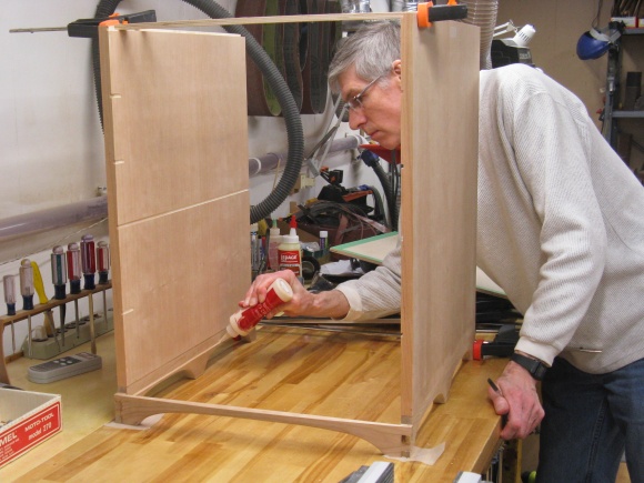
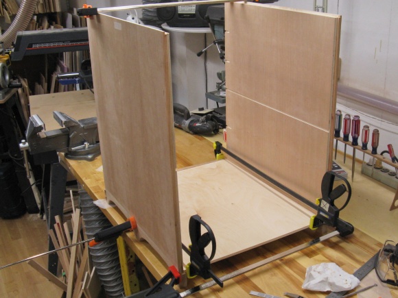
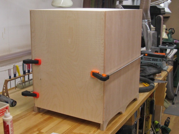
With the sides assembled, I could then look at making the transformation from two dimensions to three. I started by clamping the sides together with spacers (just scraps cut the the right length) and then glued in the front base piece.
Setting up to glue front piece in place
A generous application of glue
Once the front was in place I trimmed the floor (of 3/8"-thick plywood) to size and then glued that in place as well.
Adding glue for the case floor
Case floor in place
And finally I slid the center plywood into its slots and added the inner top. The inner top connects the cherry top to the case so it will need to support the weight of the whole drawer cabinet if/when the finished piece is lifted by the cherry top. I wanted it well connected so in addition to glue, I used six pairs of screws into the sides.
To attach the cherry top, I drilled holes in the inner top to allow me to install screws from inside. Although rather than round holes I cut slots aligned front-to-back so the top could expand and contract without stressing the screw connections. As there are 12 screws per side, I'm thinking that will support as many socks as even Sue could stuff in all the drawers.
To attach the cherry top, I drilled holes in the inner top to allow me to install screws from inside. Although rather than round holes I cut slots aligned front-to-back so the top could expand and contract without stressing the screw connections. As there are 12 screws per side, I'm thinking that will support as many socks as even Sue could stuff in all the drawers.
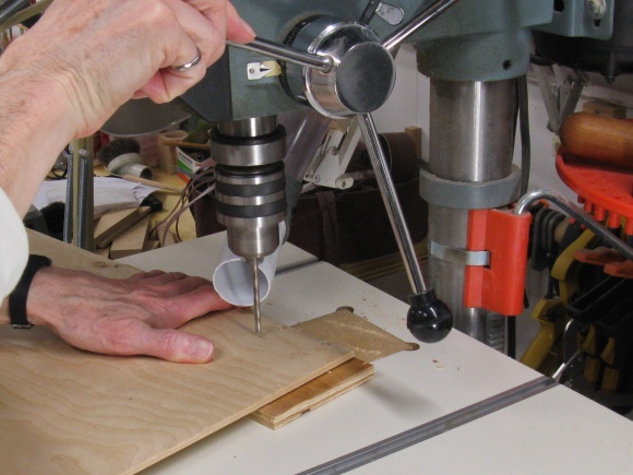
Forming slots in the case top on the drill press
Top being glued 'n screwed into place
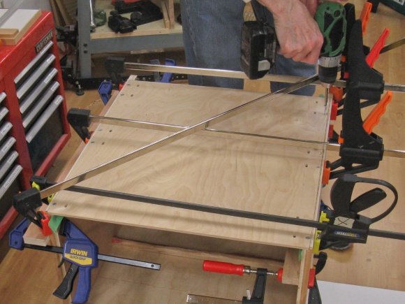
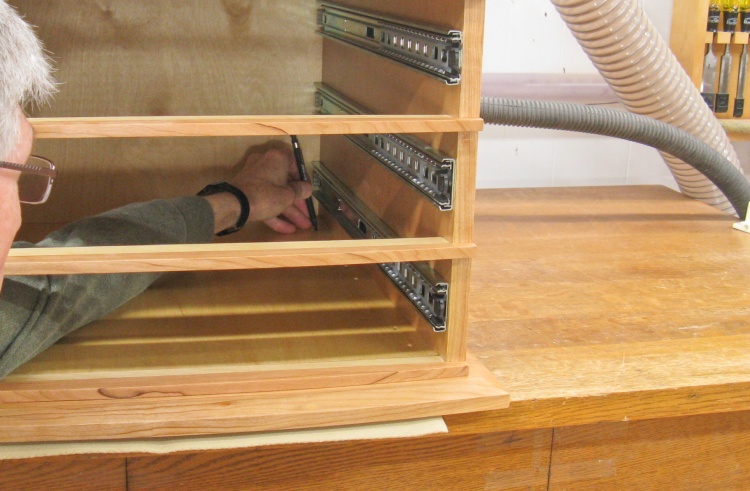
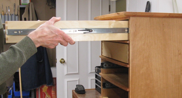
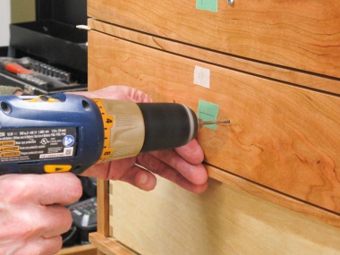
Marking hole positions for the slides
Before I started on the drawers I wanted to make sure I measured the exact width required and that meant installing the slides. So then the first steps were marking the slide positions and then as shown here, marking the screw hole locations.
As seen here I've repurposed the drawer-front curve pattern by marking it up to use as a hole-position pattern.
As seen here I've repurposed the drawer-front curve pattern by marking it up to use as a hole-position pattern.
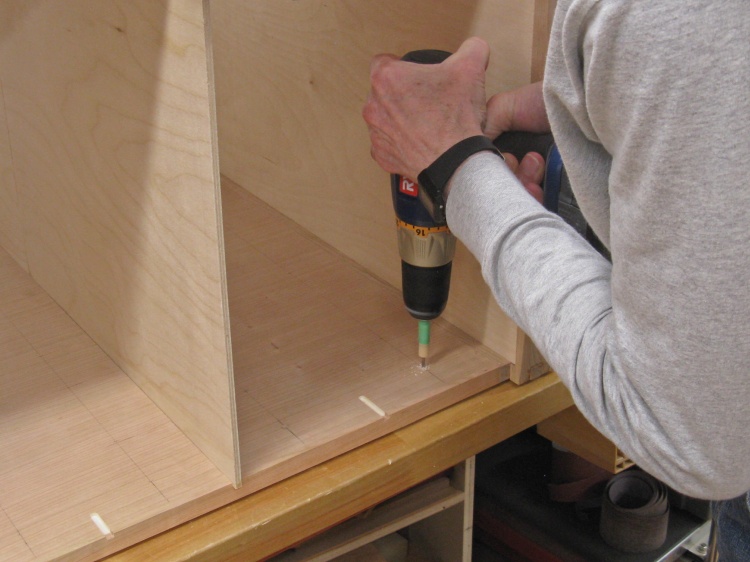
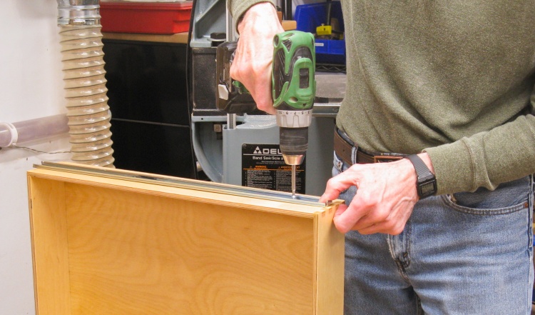
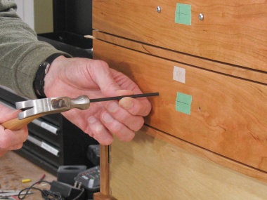
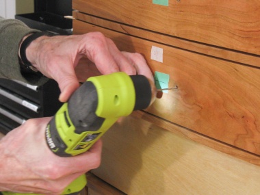
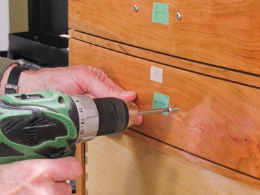
Drilling pilot holes for slide screws
And then with a solid depth guide on the drill bit to keep me from drilling right through the outside of the wall, I bored pilot holes for the slide mounting screws (4 per slide).
Once that was done, I installed all 10 slides and proceeded to measure the width. Ironically, the slide thickness varied based on pressure applied so I wasn't able to get consistent readings and I ended up just measuring the cabinet width and subtracting the nominal slide thickness.
And then all the slides came back out.
Sanding the corner joints flush
The box joints on the bottom corners were made with fingers longer than needed and those still needed to "get flush" with the surface. I accomplished that with a belt sander followed by hand sanding
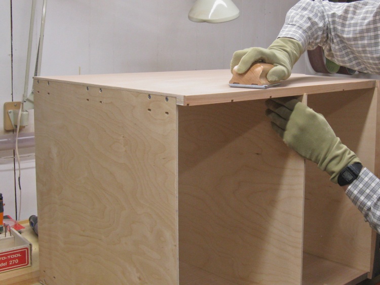
And the obligatory hand-sanding step
And then all the inside and outside surfaces were sanded with 220 grit to prepare it for finishing.
The case still needed a back. The bottom, middle and inner-top plywood sheets were in place so I could accurately mark the back to fit. I cut slots in the 1/4" plywood sheet on the inside-facing side to accept those three features - that's what I'm doing in the left-hand photo. And then as per the right-hand photo, it was glued into place.
Routing slots in the back piece
Gluing back piece in place
Adding varnish to the inside
If you tote up all the area on the inside and outside of the case, that results in a whole bunch of square footage so I decided to break the varnishing job into two smaller tasks. I started by varnishing only the inside as seen here.
I cracked open a new can of my normal Fast-Dry Polyurethane varnish and applied three coats (over three or four days), sanding between coats.
I cracked open a new can of my normal Fast-Dry Polyurethane varnish and applied three coats (over three or four days), sanding between coats.
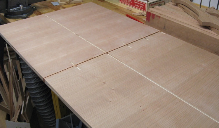
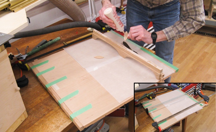
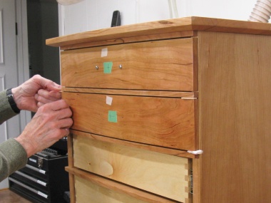
Positioning drawer dividers
I had left off the drawer dividers to make access to the inside for finishing a bit easier. After the varnish was dry, those were added on.
For accurate spacing and positioning of the dividers, I put all the dividers and drawer fronts in place with 0.081" spacers (AKA popsicle sticks) between them.
I had done this previously and had adjusted the drawer-front heights so the spacing was correct. This time I added waxed paper so when the dividers were glued down, the spacers and drawer fronts were isolated from any glue squeeze-out.
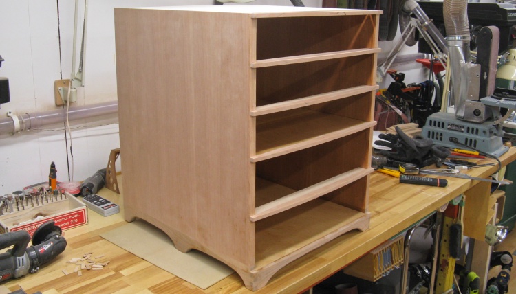
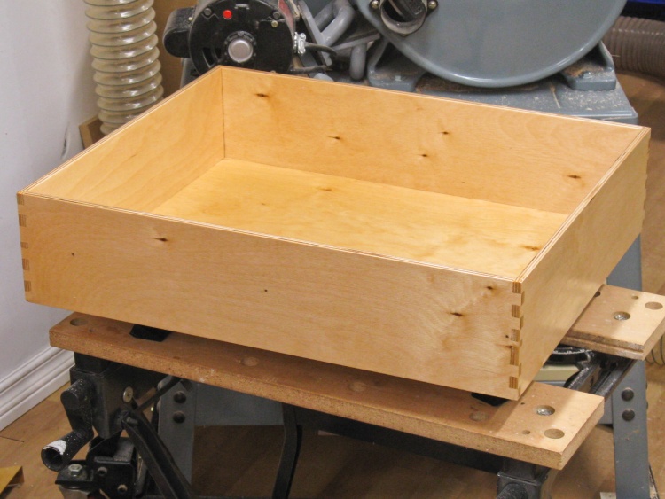
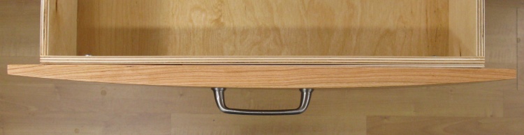
Case pretty much done
Here is the case with dividers in place.
The case still lacks outside varnish and will eventually need the drawer slides and the solid top added.
The case still lacks outside varnish and will eventually need the drawer slides and the solid top added.
The lack of outside varnish was the next thing to address. These shots show the first coat going on to the case and then the drawer fronts. It's starting to look a bit more cherry-like. I used a bristle brush for the first coat while the second and third coats employed a foam brush wrapped in cotton cloth for a smoother finish.
Varnishing the outside
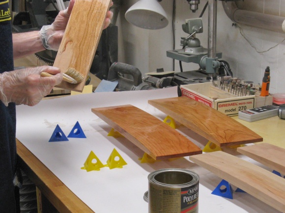
...and the drawer fronts
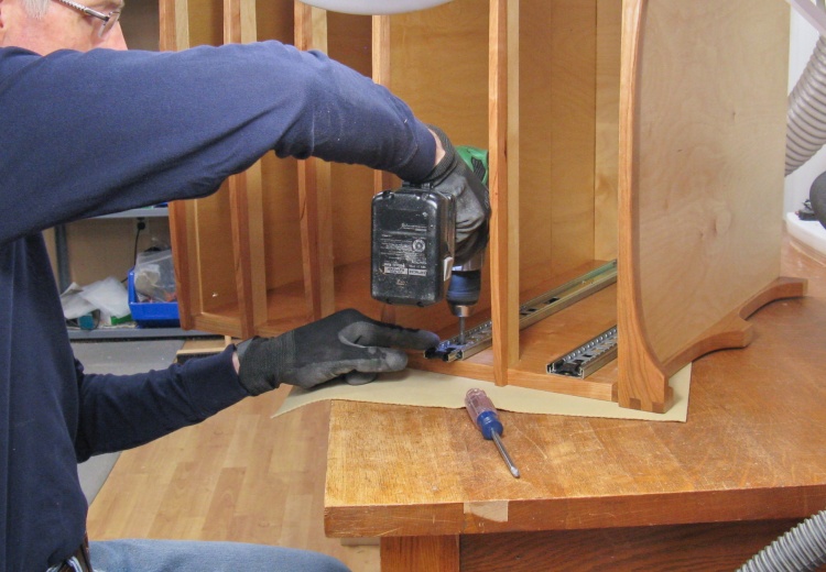
Installing the slides
After the last coat of varnish was dry, I installed the slides.
I had previously drilled holes so the slides just needed to be positioned and screwed into place.
I had previously drilled holes so the slides just needed to be positioned and screwed into place.
Drawers
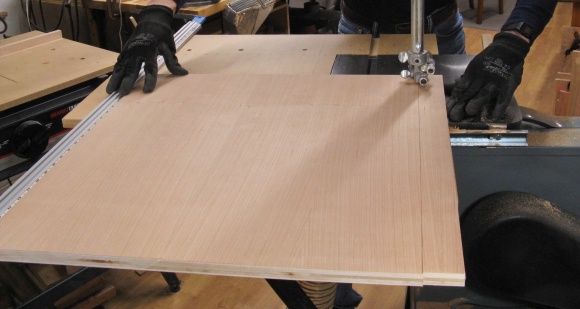
The drawer construction was independent of the case but I had needed to wait until I could measure the case dimensions to do much more than rough-cut drawer sides (since the width needs to be accurate to +/- 1/32" relative to the finished cabinet inside dimension).
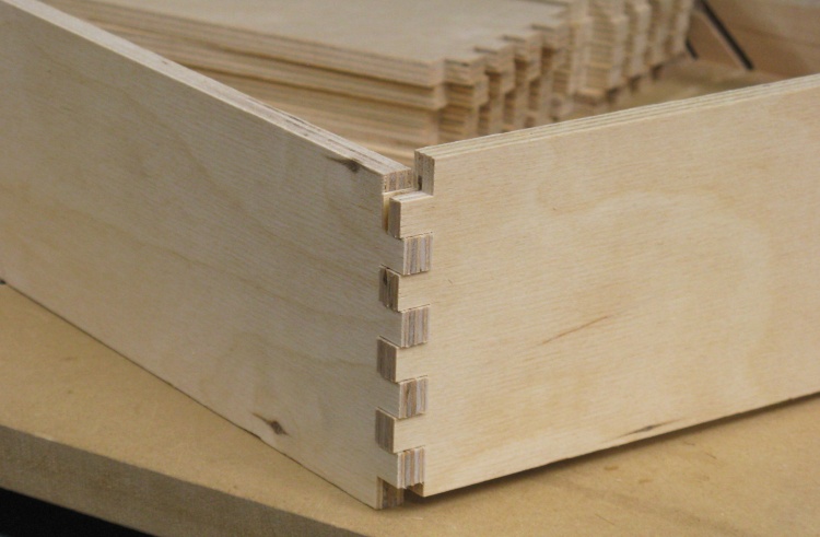
Sides for the three short drawers ready for joint routing
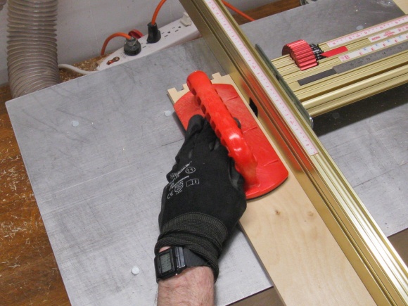
I did a test run of 3/8" box joints to establish the joint jig settings and when those joints fit together acceptably, I loaded up all the sides of the three narrower drawers to route them at the same time.
In this photo the sides are clamped to the joint sled and are ready for routing.
In this photo the sides are clamped to the joint sled and are ready for routing.
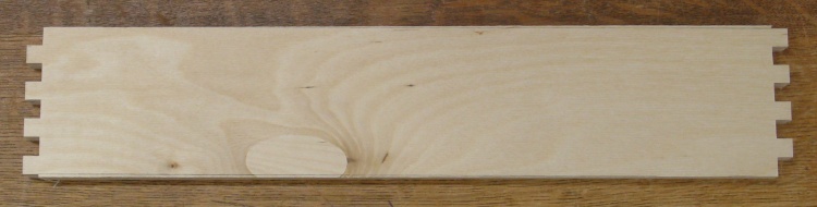
Today's lesson: review the plans first
So the good news is that the joints fit just fine. The bad news is that I had earlier decided to change the width of the joints and forgot about it so the result is what you see here. Good thing I screwed up only three of the 5 drawers...
So then I remade the drawer side blanks (I could reuse half of them) and checked out another test piece - of the proper width - with the new joint dimensions. They fit together OK and aligned correctly this time so I bravely did all the three drawer sides again.
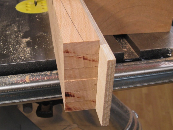
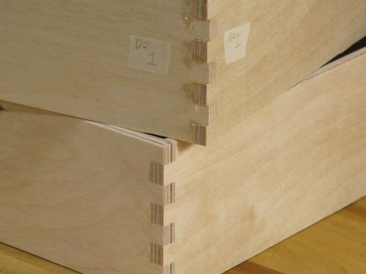
A perfectly functional set of joints
So the good news is that all the joints fit together. The bad news is that the end-to-end symmetry is...unconventional. I had done the second end of the sides in the wrong orientation.
Ah well, that's something only the builder is going to notice so I gave myself a break and declared them fine.
Ah well, that's something only the builder is going to notice so I gave myself a break and declared them fine.
Next lesson: print clearly
Then it was time for the two larger drawers. These had different joint widths so I made a careful list of the jig settings for every cut.
Unfortunately, one of my "3/8" dimensions looked more like a "1/8" so I ended up with a rather asymmetrical finger in the middle.
The joints on this project are killin' me.
Unfortunately, one of my "3/8" dimensions looked more like a "1/8" so I ended up with a rather asymmetrical finger in the middle.
The joints on this project are killin' me.
Another perfectly functional joint
OK, so the good news this time is that I screwed up on the first end of the drawer sides. That meant I could "unscrew" it by compensating at the other end.
So after careful measuring and double and triple-checking I cut the second end and Whew! - didn't screw it up. Joint is perfectly functional if a bit unconventional.
So after careful measuring and double and triple-checking I cut the second end and Whew! - didn't screw it up. Joint is perfectly functional if a bit unconventional.
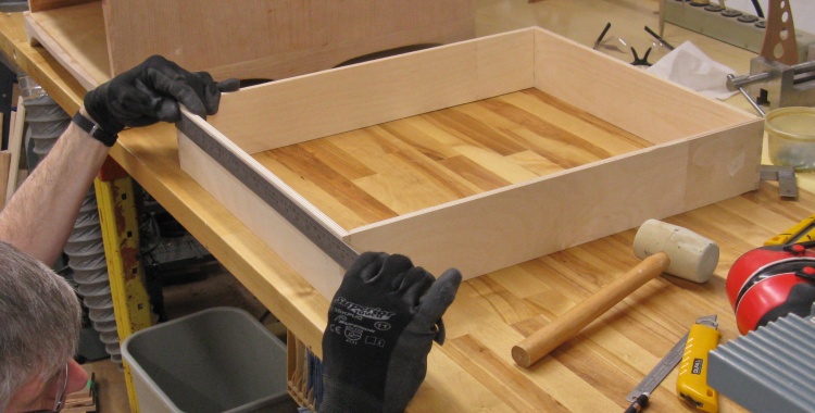
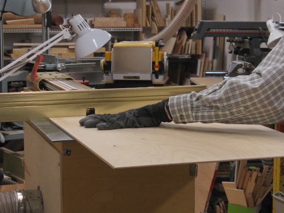
Checking drawer width
Of course my careful measuring of the case width wouldn't be useful unless the drawers were made to the proper width so here I'm rechecking drawer width - fortunately it was just as needed.
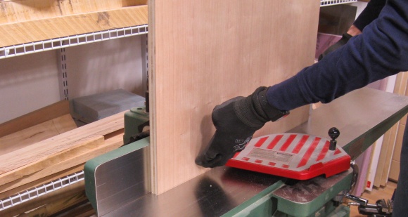
The drawer side heights were made about 1/16" taller than I needed so I marked and trimmed them as appropriate so the top and bottom edges were all flush.
The drawer side heights were made about 1/16" taller than I needed so I marked and trimmed them as appropriate so the top and bottom edges were all flush.
The bottom panel of each drawer is meant to fit into rabbets on the bottom edges of the sides. Those were cut with the router as shown in the left-hand photo. Since the end of the slot ends up rounded by the router bit, I followed that up by hand-trimming the round ends into a state of squareness so the bottom panel would fit without interference.
Routing bottom rabbets
Squaring off the inside corners
I wanted the top edges of the drawer sides to be rounded and smooth. I managed to find an ancient router bit I had inherited from my dad that turned out to be just what was needed (or that "worked tickety-boo" as he was wont to say). I routed the top edges so they were slightly rounded and then hand-sanded to get a bit more curve and to round the remaining corners. They were sanded to 320 grit so the tops were quite smooth to the touch.
Routing the drawer tops round
...and sanding smooth
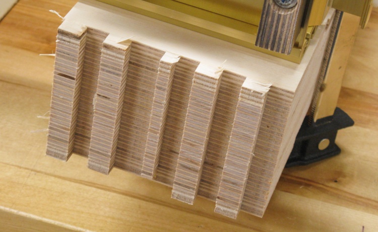
The next step was gluing the drawers together. I first taped the inside corners to keep them free of glue squeezed out of the joints. Note that glue on the outside faces isn't a problem as those get sanded later anyway to bring the joint fingers flush.
I clamped together the front and back sides and then used a cut-down bristle brush to apply glue to both in the same operation. This saved time which is a critical commodity in glue-up operations.
I clamped together the front and back sides and then used a cut-down bristle brush to apply glue to both in the same operation. This saved time which is a critical commodity in glue-up operations.
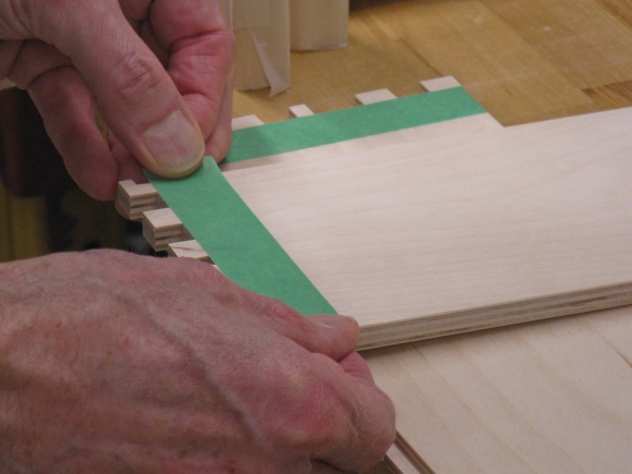
Masking the inside corners
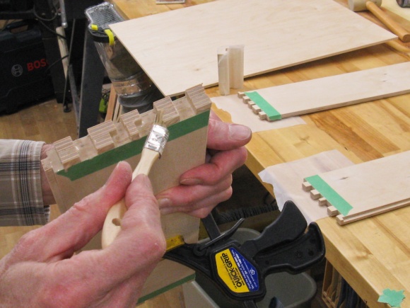
Brushing glue onto a pair of sides
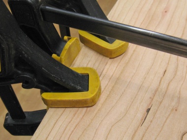
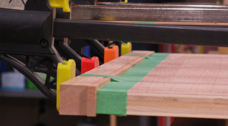
In order to get clamping pressure on the full length of the joints, I made some corner brackets that would contact the drawer sides and provide clearance for the protruding joint fingers. A layer of waxed paper kept them from being glued to the drawers. Then I used a band clamp to pull everything together and inserted the (unglued) bottom to keep the drawer square.
This technique worked pretty well, being simpler to set up than conventional clamps and providing more-even pressure. However I needed to visually verify that the joints were tight (and tap them together if not) before letting the joints dry since the band wasn't able to exert the same pressure as individual clamps.
Once the joints were set, I applied glue to the bottom and clamped that into place to dry.
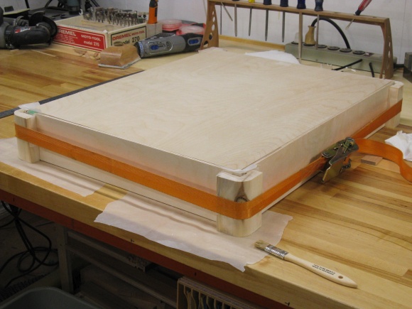
Band clamp with some custom corner frames clamping the drawer after gluing

The bottom was glued in after the side joints were set

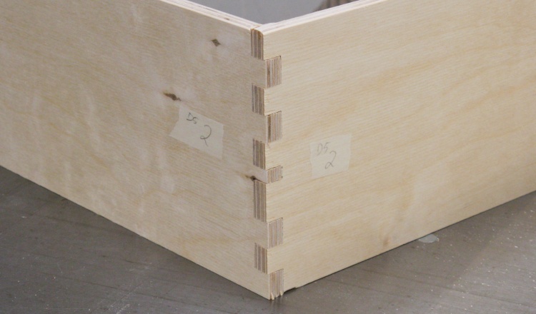
Sanding the corner joints flush
Once the glue was dry, I used the belt sander to sand the protruding joint fingers flush with the drawer sides. This also removed any glue squeeze-out. I followed that up with some hand sanding of all the surfaces of the drawer.
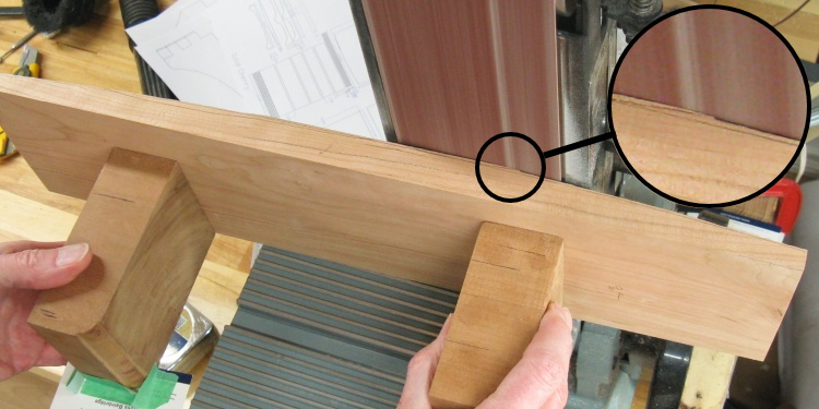
Before and after joint sanding
This is the before-and-after-sanding shot of a couple corner joints.
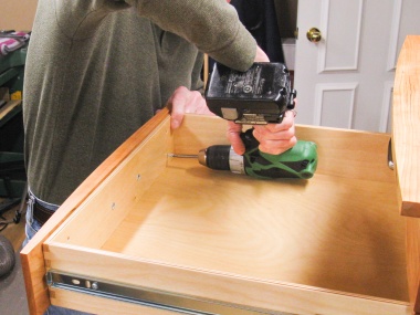
Drilling for slides
The last operation on the drawers was to mark and drill the screw holes for the drawer portion of the slides.
I used three screws per slide - stubby little #8 x 3/8" guys that wouldn't protrude through the drawer sides.
I used three screws per slide - stubby little #8 x 3/8" guys that wouldn't protrude through the drawer sides.
The first coat of varnish on one of the taller drawers
The completed drawers had varnish applied to all 10 surfaces (14 if you count top edges).
As with the other components I used three coats of Minwax Fast-dry Poly.
As with the other components I used three coats of Minwax Fast-dry Poly.
Final Assembly
At this point, all the parts are completed and the drawer set just needs to be put together.
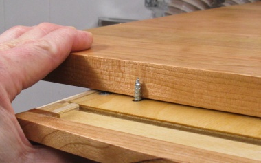
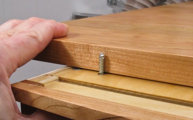
The first order of business was to install the cherry top. It would be held by screws from the inside going up through the slots of the inner top. I checked for appropriate screw lengths and a 1" screw came a bit too close to the surface for comfort while the 3/4" version didn't give enough bite into the wood. I kind of needed a 7/8" screw but they don't "do" screws to that resolution so I just ground off 1/8" of the pointy bit of the 1" screws; that worked.
The first order of business was to install the cherry top. It would be held by screws from the inside going up through the slots of the inner top. I checked for appropriate screw lengths and a 1" screw came a bit too close to the surface for comfort while the 3/4" version didn't give enough bite into the wood. I kind of needed a 7/8" screw but they don't "do" screws to that resolution so I just ground off 1/8" of the pointy bit of the 1" screws; that worked.
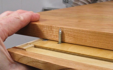
Too long
Too short
Just Right!
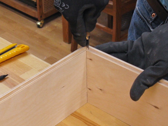
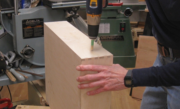
Marking the top with pilot hole locations
The case was flipped upside-down and properly positioned on the inverted top so I could mark the twelve screw hole positions like I'm doing in this shot.
Pilot holes for the screws were then bored on the drill press and the top was installed on the case.
Pilot holes for the screws were then bored on the drill press and the top was installed on the case.
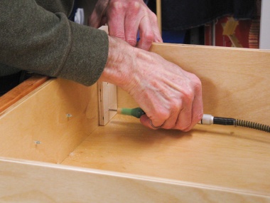
Installing a slide on a drawer
I switched over to the drawers and installed the drawer portion of the slides in the already-drilled holes.
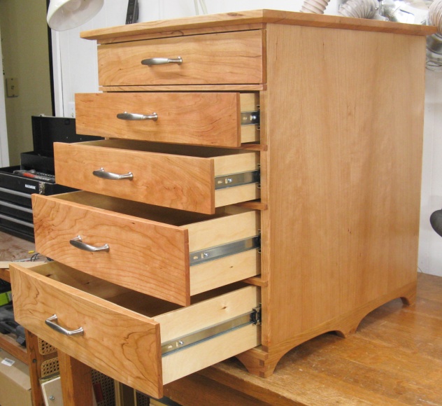
Sliding top drawer into place
Then the drawers could be inserted in the cabinet by engaging the slides.
The final step was to install the drawer fronts. They already had the holes for the handle screws drilled and needed to be correctly installed on the drawer bodies.
The fronts had to go in place for accurate positioning which of course covered up the drawer body. I ended up with a multi-step procedure to get them properly fastened together;
The fronts had to go in place for accurate positioning which of course covered up the drawer body. I ended up with a multi-step procedure to get them properly fastened together;
1. Position drawer
2. Mark hole centers
[So small pilot hole is properly centered]
3. Drill small pilot holes
[Prevents splinters when drilling normal pilot hole]
4. Drill normal pilot holes
[Fits temporary screws]
5. Install temporary screws
[They hold the front to the body]
6. Drill mounting-screw pilot holes
[Through body and into front]
7. Drill clearance holes
8. Reposition front and install screws

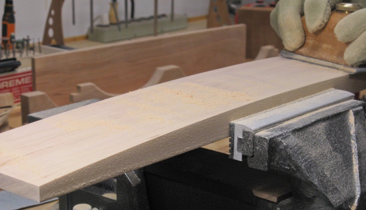
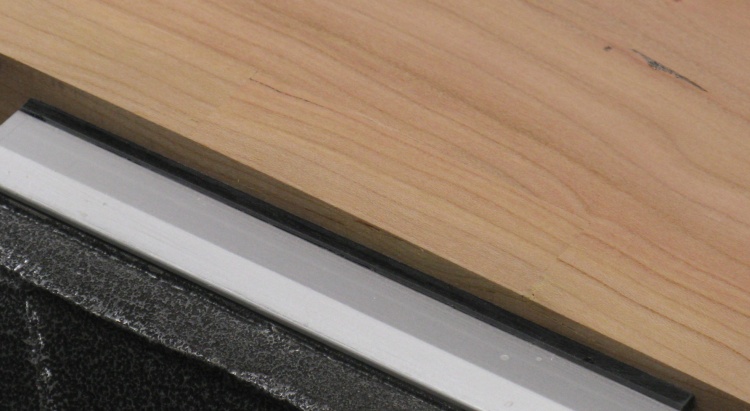
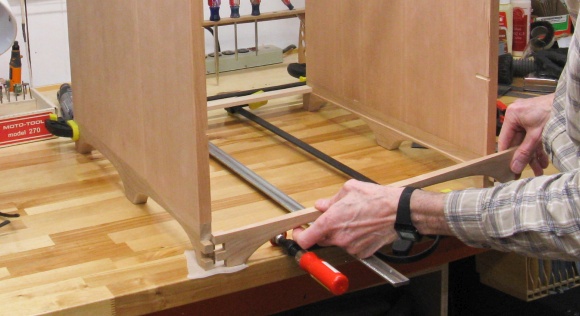
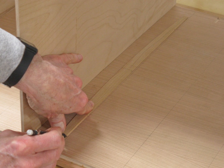
Drawer squareness failure
I found when installing the bottom drawer front that it didn't sit flush on both sides. A bit of investigation showed that I had somehow managed to make the drawer a bit out of square - something the inserted bottom was supposed to have prevented.
In this shot you can see that the near side of the drawer is about 1/8" further back than the far side, evident when comparing it to the edge of the cherry piece below.
In this shot you can see that the near side of the drawer is about 1/8" further back than the far side, evident when comparing it to the edge of the cherry piece below.
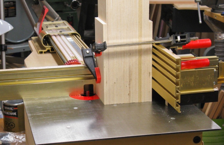
Making a narrow wedge
I decided to interpose a thin wedge that would taper from 1/8" on the near side to zero on the far side (although it was cut short where it was about .035" thick).
I started with a piece of 1/8" plywood and sanded it into a wedge shape on the belt sander as seen here. The taped-on backing board keeps the thin plywood straight for the sanding.
I started with a piece of 1/8" plywood and sanded it into a wedge shape on the belt sander as seen here. The taped-on backing board keeps the thin plywood straight for the sanding.
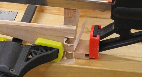
Wedge in place, squaring up drawer front
The wedge was drilled with the appropriate holes and the front re-installed over it.
It seemed to do the trick.
It seemed to do the trick.
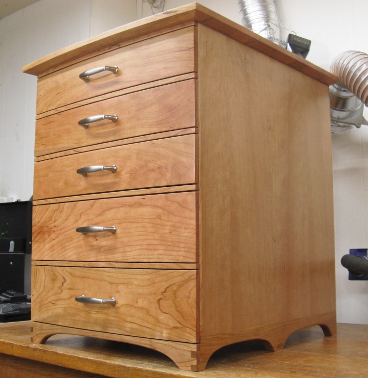
Done
And that was it.
Working drawers!
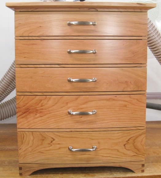
The front view


