This little table supports the shiny aluminum Incra LS Positioner jig on the router table. Technically it's more of an equipment extension, as opposed to a jig which generally makes processes easier/faster/safer/more accurate/possible. But hey - it's another excuse for a web page.
The positioner itself has about a 17" range of motion so you'd need a pretty wide router table to be able to install it without any modifications. If you have the room you can of course buy router tables wide enough to mount it but for my crowded shop I opted for a space-saving add-on table instead.
The positioner itself has about a 17" range of motion so you'd need a pretty wide router table to be able to install it without any modifications. If you have the room you can of course buy router tables wide enough to mount it but for my crowded shop I opted for a space-saving add-on table instead.
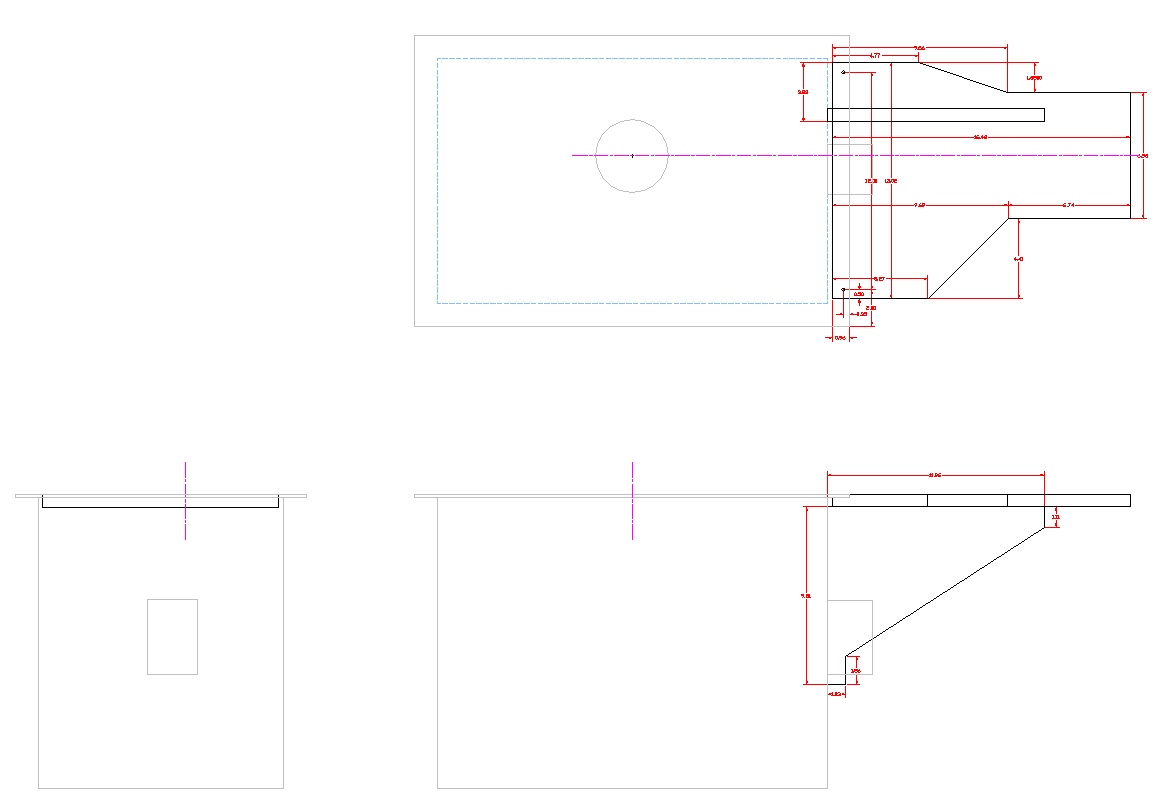
The plan, with indecipherably-small dimensions at this scale
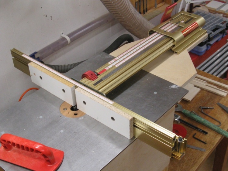
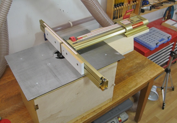
The LS Positioner in place
This shows the whole of the setup. The positioner base is mounted to the plywood table (the subject of this page) which is in turn bolted to the metal top of the router table.
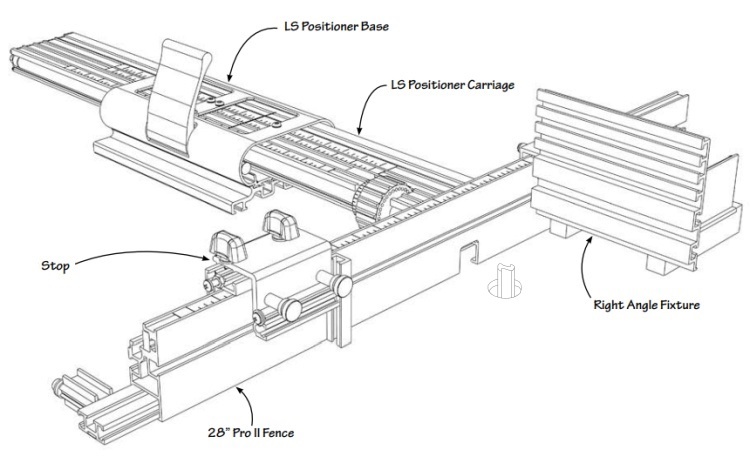
An annotated sketch of the positioner (with all the extra bits on)
In terms of background, this sketch illustrates the LS Positioner parts. By the way, LS stands for Lead Screw, a long threaded rod with 32 threads per inch which is an integral part of the tool.
The fence can be slid through the base and locked to fix it at a specific distance from the router bit and the key to the fence is that it can be easily and accurately positioned anywhere in its range.
The fence can be slid through the base and locked to fix it at a specific distance from the router bit and the key to the fence is that it can be easily and accurately positioned anywhere in its range.
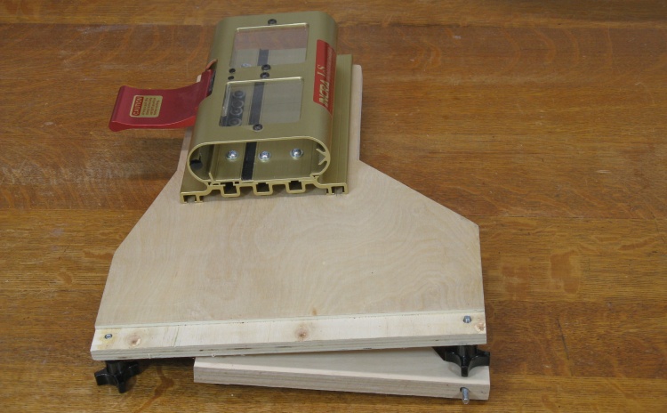
In the folded position
The actual table was pretty simple. It just consists of a couple of shaped pieces of 3/4" plywood and some 1/4-20 hardware.
This photo shows the table in its folded configuration that takes less room for storage.
This photo shows the table in its folded configuration that takes less room for storage.
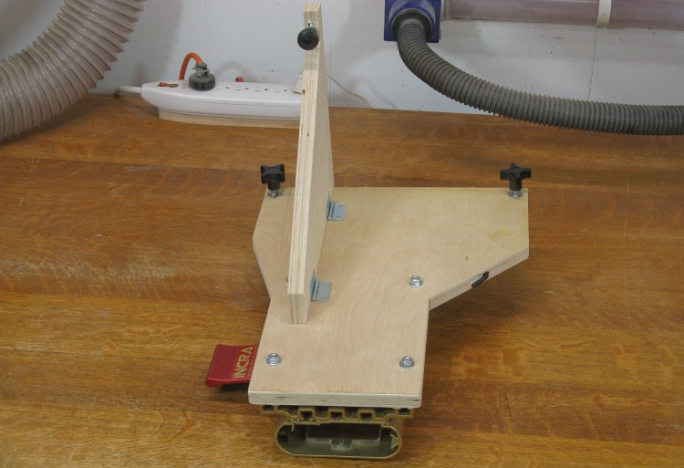
...and open
This bottom view shows the hinged vertical support. The bolt-equipped knob at the top of the photo (which of course is at the bottom of the table in normal orientation) is used to fasten the vertical support to the wall of the router table to prevent any sagging of the table top.
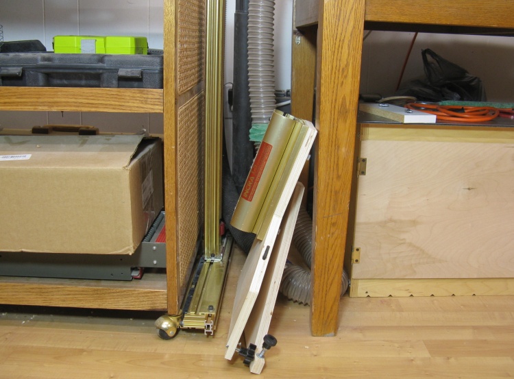
Table and positioner stored away
This is the normal storage location of the table, leaned up against a worktable leg with the actual positioner beside it.
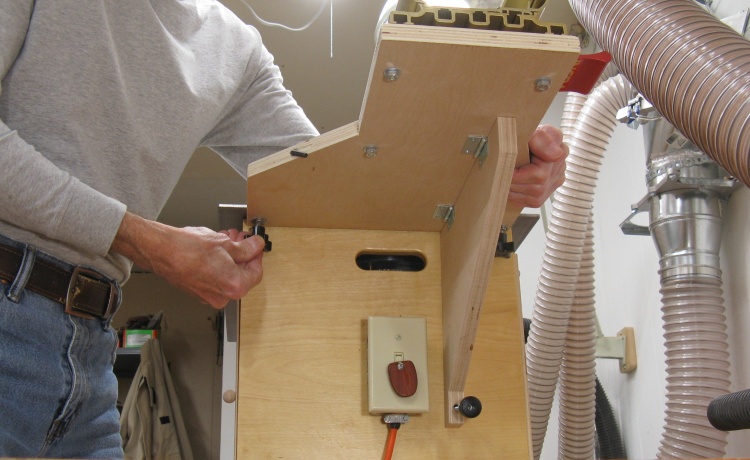
Installing the table
It takes only a minute or so to install the table. The vertical support is folded out to sit against the wall of the router table and two captive knobs equipped with 1/4-20 threads are turned into threaded holes in the steel top of the router table.
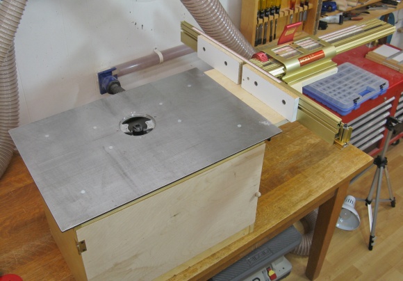
Lastly the aluminum positioner fence assembly is inserted into the base that is mounted on the table top.
Lastly the aluminum positioner fence assembly is inserted into the base that is mounted on the table top.
These shots show one of the holes that needed to be drilled and threaded into the table top, along with the flush mount of the table when it is in place.
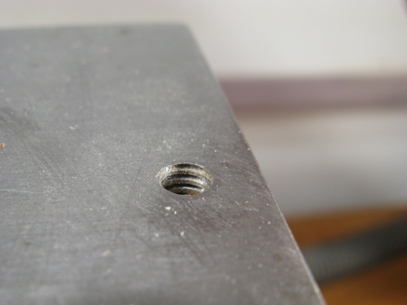
One of the threaded holes
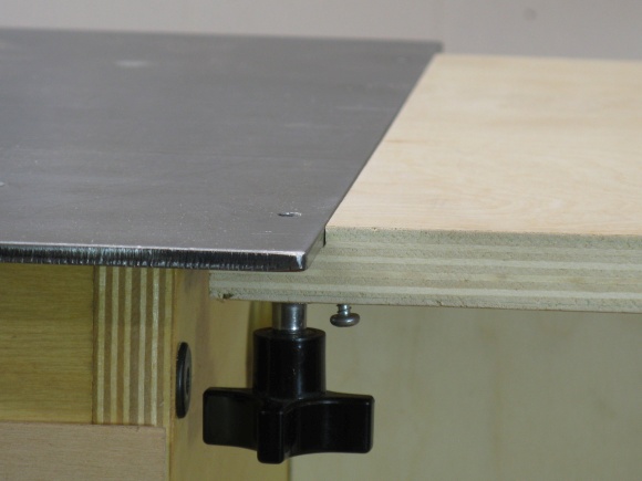
Table sits flush with the top when in place
The positioner is available in a few lengths but this is the shortest version at 17". These shots show the fence at the closest and furthest from the router bit.
Positioner fence right at the bit
Fence as far away as it goes
The carriage of the positioner has a number of slots for rules. They can all be changed out or slid around to set a zero point wherever desired. There is of course the standard ruler and then others for making specifically-spaced cuts etc. The carriage and fence can be locked on any thread of the internal lead screw which puts it at even increments of 1/32" (or 0.03125"). Then it can further be moved in 0.001" increments by rotating the red knob the desired amount.
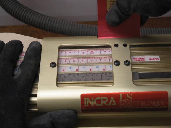
A plethora of scales used for distance setting
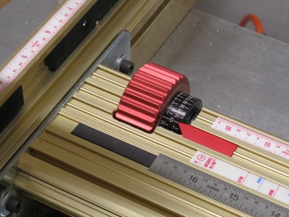
And a big red knob with 0.001" setting resolution
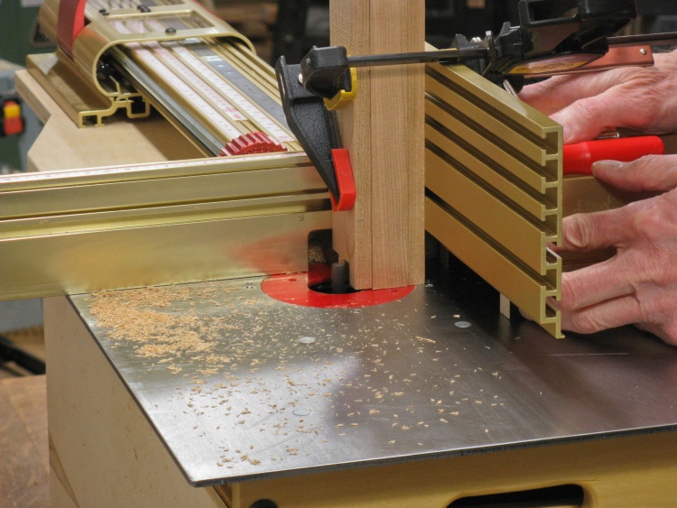
The whole shebang in use
This shows the fence in use at its main purpose of cutting joints. Here I'm working on some box joints for a set of drawers.


