When I originally thought about making a lock, it was going to be a sort of puzzle lock, wherein a hollow cylindrical key would have a hidden "maze" inside it into which a pin in the lock would fit. It would have been necessary to maneuver the angle and insertion depth of the key to have the pin follow the maze until it was fully engaged. I eventually decided that a conventional lock mechanism would be much more interesting, so I switched over to the one described here.
I thought I knew how a standard cylinder lock worked, and it didn't even occur to me to do the research to verify that before I started. Of course we didn't yet have Internet access back in '97 so that would have meant a trip to the library and flipping through some books (let's see - 1997 - I would have been driving my '92 Subaru Legacy. Great car, but I still didn't drive it to the library). However a subsequent check (years later and post-internet) confirmed that I'd been correct.
I thought I knew how a standard cylinder lock worked, and it didn't even occur to me to do the research to verify that before I started. Of course we didn't yet have Internet access back in '97 so that would have meant a trip to the library and flipping through some books (let's see - 1997 - I would have been driving my '92 Subaru Legacy. Great car, but I still didn't drive it to the library). However a subsequent check (years later and post-internet) confirmed that I'd been correct.
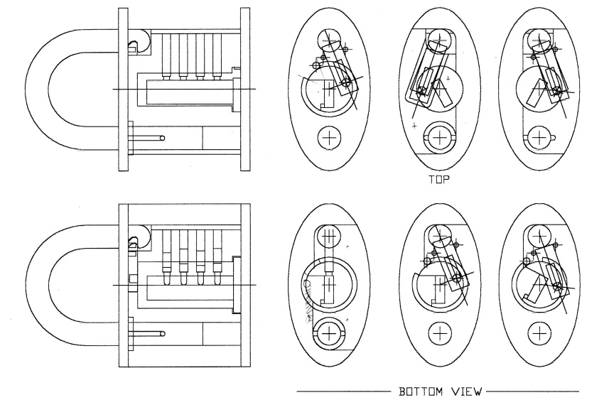
Part of the plans - scanned in from a paper copy
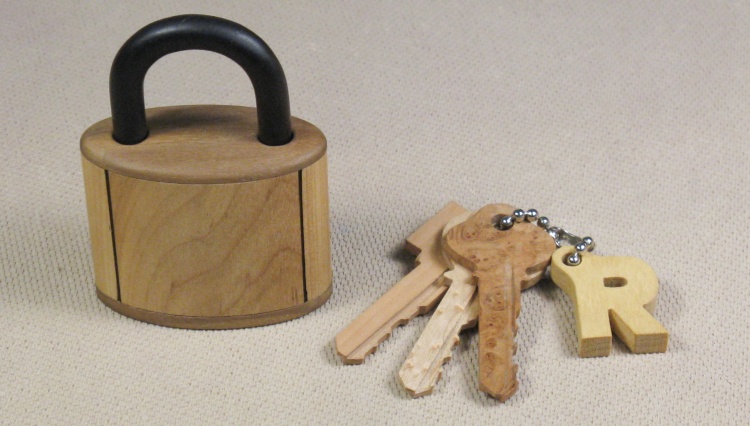
Lock and keychain
The original CAD files for the lock were lost many years ago likely due to a hard drive failure, and the backups I had made on CD-R/W couldn't be read by the new computer. Grrrr. I've never liked the optical disc format; Data disc or audio disc? Leave disc open or close disc? Can't write to a closed disc. Large size, poor compatibility, slow operation. I abandoned them after the backup fiasco. Fortunately technology in the form of flash memory eventually caught up. End of rant.
This shot shows the "back" of the padlock and the set of three keys. The center light-colored key is the Birdseye Maple one that opens the lock. The bottom key is made from Swiss Pear while the top one is Maple Burl.
This shot shows the "back" of the padlock and the set of three keys. The center light-colored key is the Birdseye Maple one that opens the lock. The bottom key is made from Swiss Pear while the top one is Maple Burl.
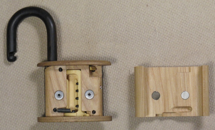
Side cover removed showing cylinder and pins
With the side cover off, the yellow cyllinder is visible with the four pins protruding through from the right.
The dark-colored spring returns the cylinder to the normal position after it has been rotated with the key to open the lock. The latch that holds the hasp is also visible in the upper-right-hand corner.
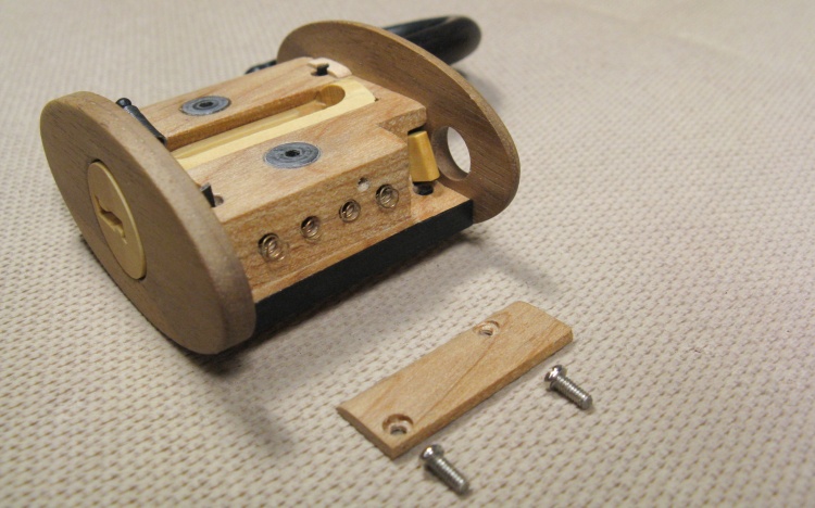
Pin cover removed showing pin springs
A small wooden plate is used to hold the lock pins and their springs in place. The small springs can be seen protruding a bit after the plate was removed.
After failing to find appropriate springs anywhere else, it ocurred to me that I could just go a locksmith for them. I hit up the local Burnett's Keys and after explaining what I was doing, they just handed me a few, free of charge if I remember correctly. They were perfect except for being a bit long, so I just trimmed them down a bit.
After failing to find appropriate springs anywhere else, it ocurred to me that I could just go a locksmith for them. I hit up the local Burnett's Keys and after explaining what I was doing, they just handed me a few, free of charge if I remember correctly. They were perfect except for being a bit long, so I just trimmed them down a bit.
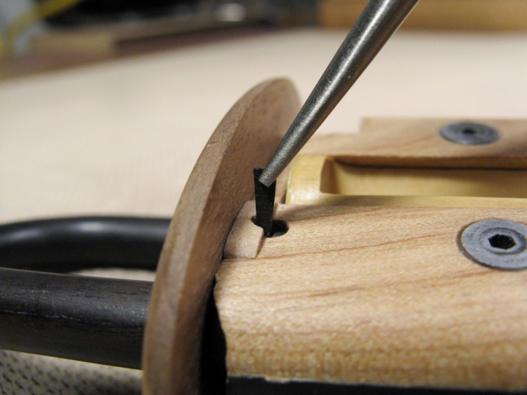
Removing one of the wedges that holds on the top & bottom
The top and bottom covers are held in place with slotted pegs. Hard African Blackwood wedges like the one shown here go through the slots to draw the covers in and hold them in place. There are two pegs each on the top and bottom covers.
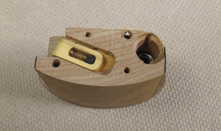
Top cover off showing the latch (yellow piece)
With the top cover off, the yellow Boxwood latch is exposed. It engages with a slot in the hasp to hold it closed (see further down for part names).
The black part at the right end of the oblong hole in the latch is the pin attached to the cylinder which retracts the latch when the cylinder is turned.
When the hasp is squeezed to the lock body to close it, the rounded hasp end pushes aside the rounded edge of the latch (since the spring lets it move) and the latch snaps back into the hasp slot to hold it in place.
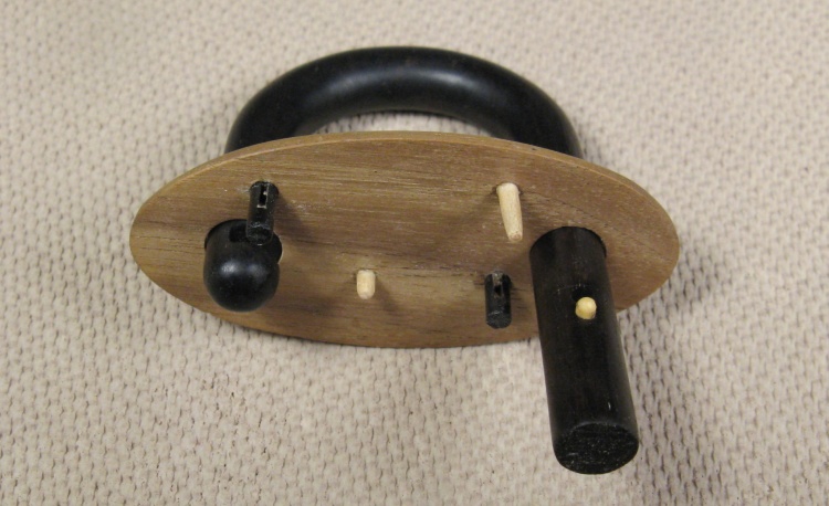
Top cover showing slotted pegs, alignment pegs and hasp
The two black slotted pegs are visible in this shot of the top cover assembly.
Also visible are the two lighter-colored toothpick-sized pegs (which were in fact made from toothpicks) that help align the cover with the body. You can also see the small yellow retaining pin for the hasp that limits how much it can travel.
Also visible are the two lighter-colored toothpick-sized pegs (which were in fact made from toothpicks) that help align the cover with the body. You can also see the small yellow retaining pin for the hasp that limits how much it can travel.
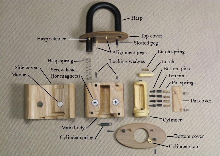
Exploded view showing all the parts
This shows the lock fully disassembled except for glued parts.
There are some drawings down further that describe the operation of the critical parts of the padlock.
There are some drawings down further that describe the operation of the critical parts of the padlock.
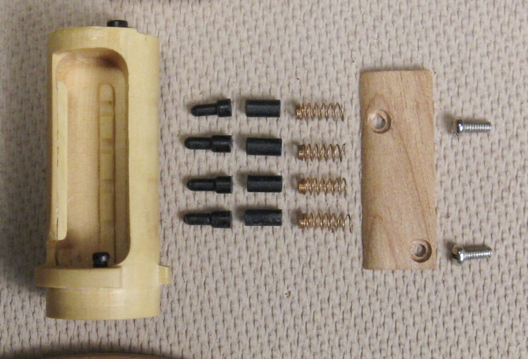
Cylinder pin detail
This is of course the critical bit, showing the yellow Boxwood cylinder and the African Blackwood pins. A close inspection shows that the length of the fatter sections of the bottom pins are different lengths, which define the keying for the lock.
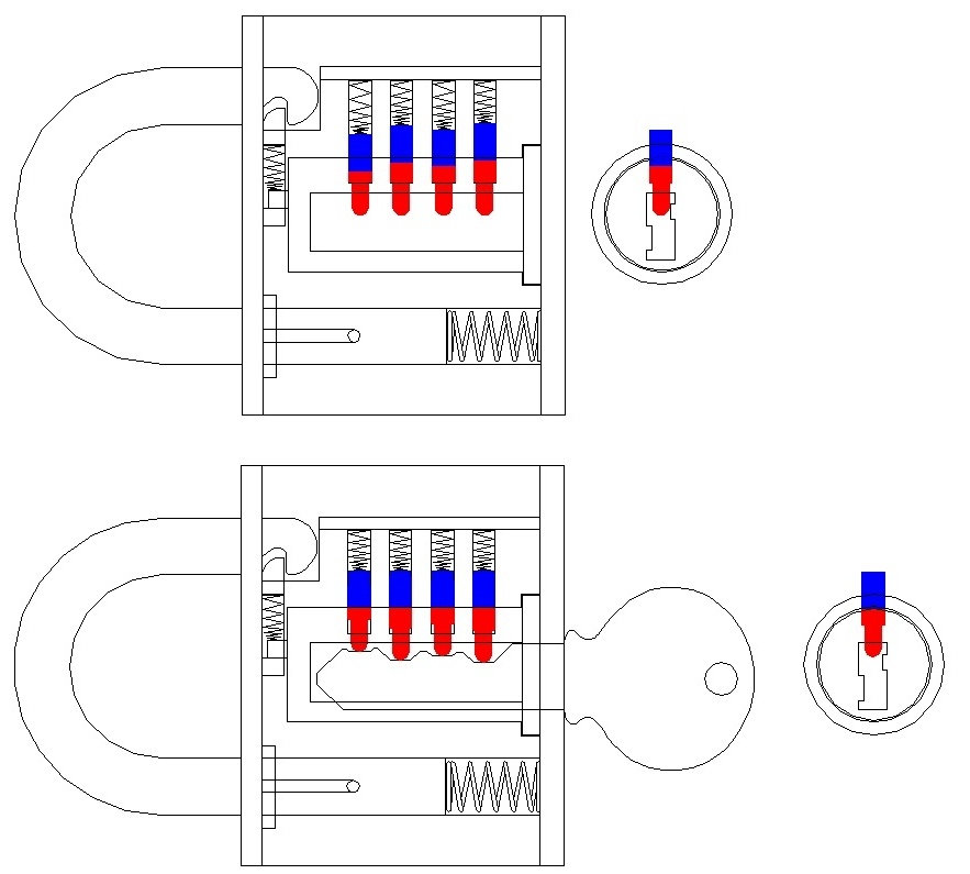
Lock pin operation diagram
This diagram shows the operation of the lock;
In this upper figure there is no key inserted, and the top pins (blue) are forced down by the springs and go into the holes in the cylinder to prevent it turning.
When the proper key is inserted as shown here, the bottom pins are pushed up the correct amount so where they contact the top pins is exactly at the edge of the cylinder so then the cylinder is free to turn.
Any other key would push the pins up incorrect amounts so either the top or bottom pins would prevent the cylinder from turning.
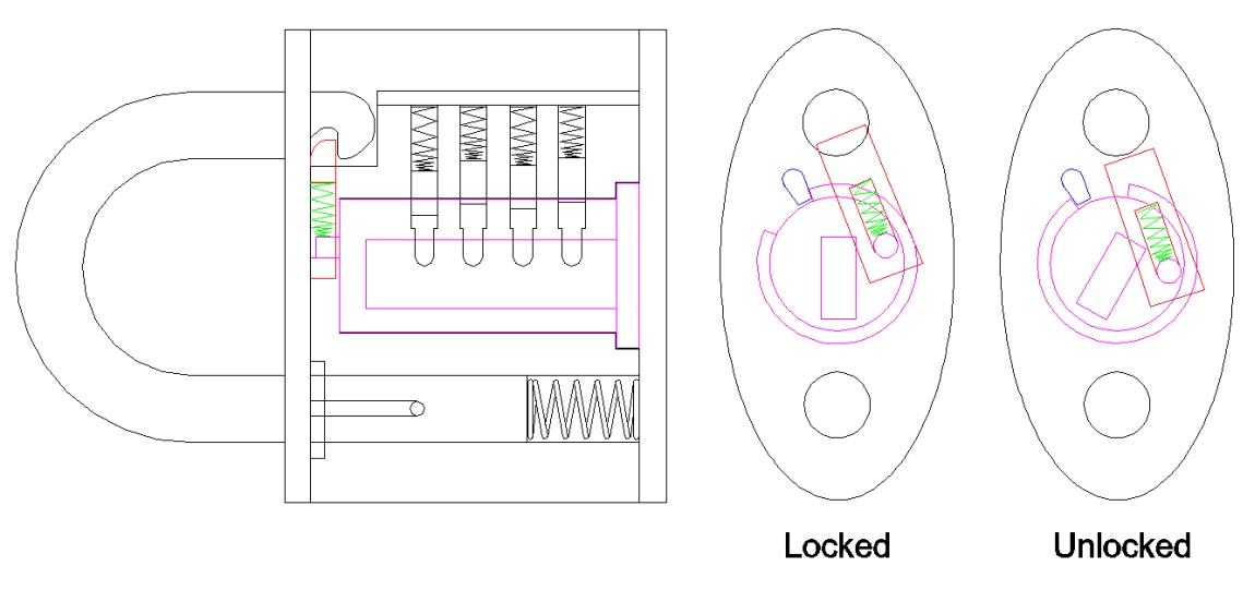
Latch operation diagram
This diagram shows the operation of the latch (the red rectangle). In the "Locked" state it protrudes into a notch in the hasp (top black circle), preventing it from coming out. When the key is inserted and turned, the latch is pulled away and the hasp pops out as shown above for "Unlocked".
The cylinder (purple part) rotation is limited by an outer flange with a section cut out of it. The cylinder stop (blue) limits the rotation.
The cylinder (purple part) rotation is limited by an outer flange with a section cut out of it. The cylinder stop (blue) limits the rotation.


