A number of years ago, I had seen a couple decorative wooden pedestals in a somewhat eclectic interior design store. I really liked the designs, but I had no real need for them. I kept an admiring eye on them on my infrequent visits to the store until they eventually disappeared after several years. More recently I decided I had an application for a pedestal, but given the time lag, the store wasn't able to help me. Unfortunately, I no longer had a clear recollection of what they looked like, and even pouring over hundreds of images of contemporary and antique pedestals didn't ring any bells. I ended up selecting a few features that I liked and synthesizing the current design from those.
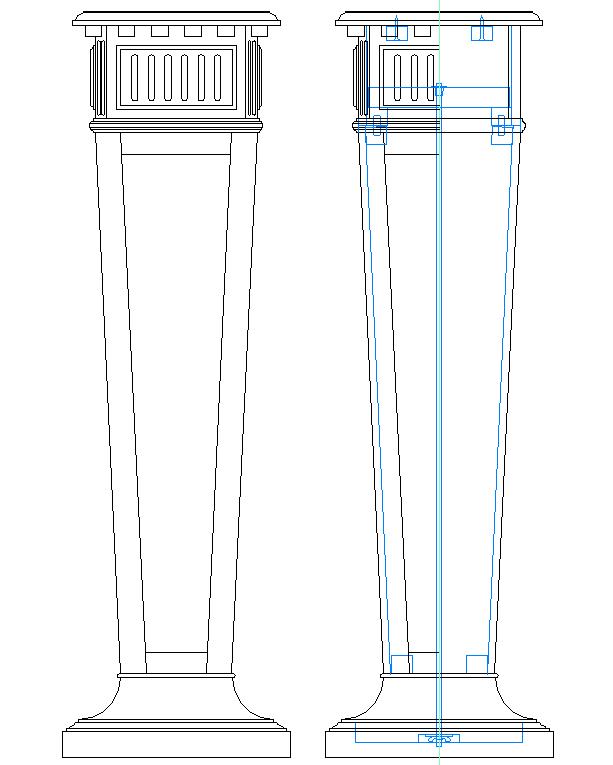
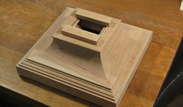
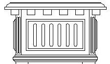
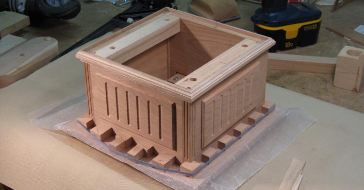
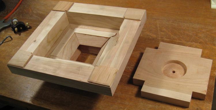
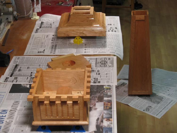
Exterior and Interior views
I chose cherry for the pedestal since it would match a table we also had in the sun room. But the problem with making this unit was that I didn't have any appropriate tools for making nice 45 degree angles (i.e. any type of rotating-blade saw). This was a bit of an issue since the whole thing is essentially made up of pieces forming 90 degree corners. I decided to take the approach of simply avoiding 45 degree joints wherever possible. However I couldn't see any way of avoiding them on the base, so that meant making use of someone else's equipment.
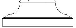
Base
Base arc construction options
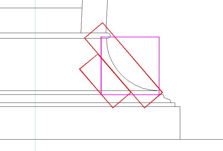
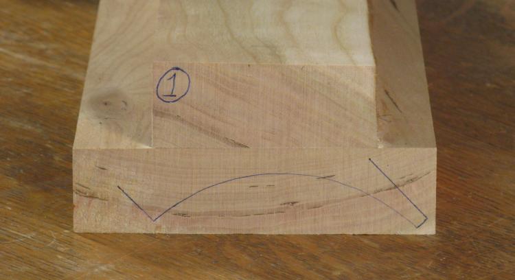
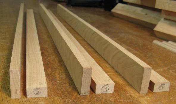
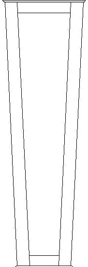
The base had a couple of interesting issues. I set aside the 45-degree-cut situation for later and concentrated on the wood. The large arc on the base just calls out to be made from a piece of wood with a square cross-section and a dimension of a bit over 2 inches like the purple square in the sketch. Unfortunately it's difficult to find anything over 2" locally and I didn't really want to order a special piece. However it turns out that the arc itself is less than 1" deep, so that let me make a laminated assembly so that a 1"-thick plank would comprise the exposed part of the arc as can be seen with the red pieces. It just needs to be assembled at the appropriate angle.
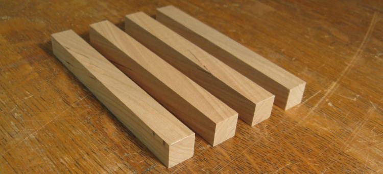
Base laminated pieces
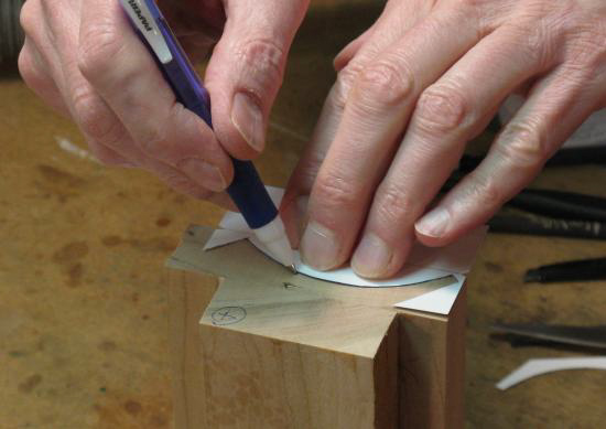
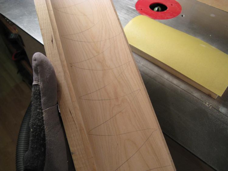
Marking the arc
Marked end
Above the two-piece laminated sections are shown as well as a shot of the ends being marked for the proper curve and angle using a little cardboard pattern.
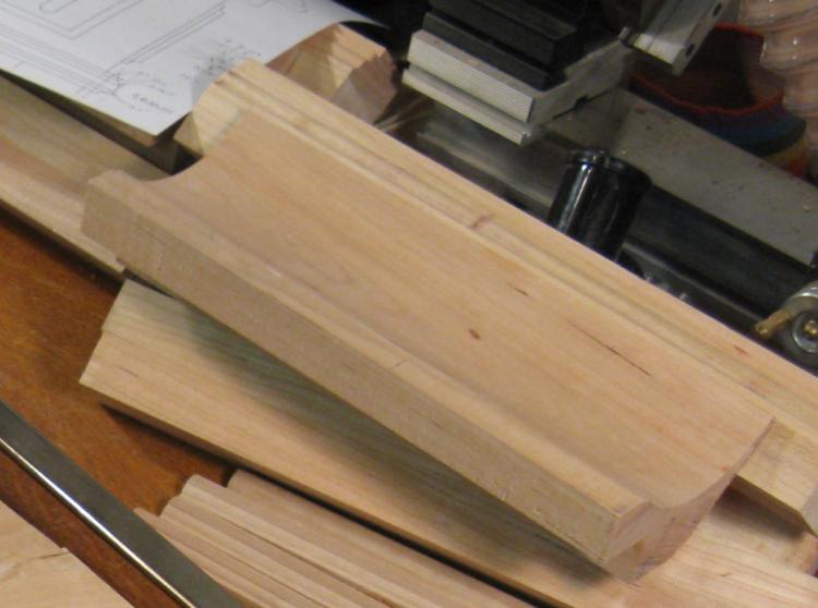
Routing the arc
Arc roughed out
Sanding form
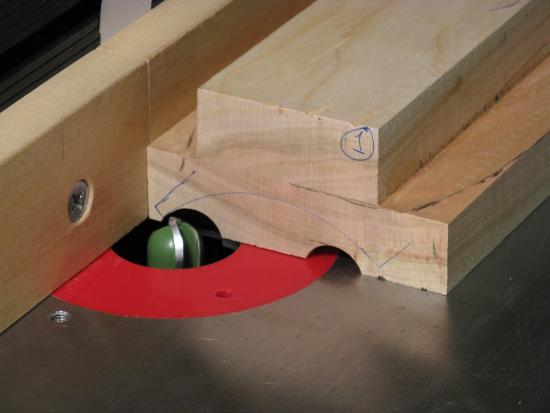
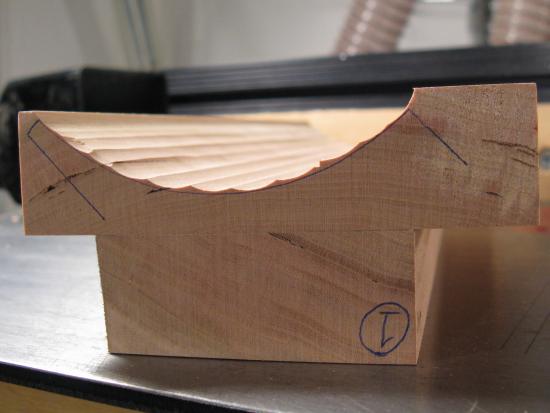
The main part of the arc was hollowed out using a bullnose bit on a router table. The bit height and fence position were set up to take out a section right next to the line and then all four pieces were done with that setting. The settings were changed for the next "bite" and then repeated.
The next step was to smooth off the "jaggies". I started by first using the curved end of a belt sander to get most of the extra material off, and then switching to a sanding jig with the appropriate curve. This process took an unfortunate amount of elbow grease but ultimately worked reasonably well.
The next step was to smooth off the "jaggies". I started by first using the curved end of a belt sander to get most of the extra material off, and then switching to a sanding jig with the appropriate curve. This process took an unfortunate amount of elbow grease but ultimately worked reasonably well.
Marked for final sanding
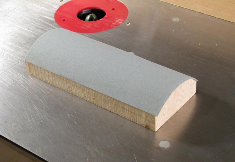
Here most of the coarse sanding is done and the curve has been marked with pencil so I could ensure that I was getting contact of the sandpaper form over the full face of the curve. This photo has the finer yellow sandpaper as opposed to the coarser blue paper in the shot above.
Completed arc pieces
This rather fuzzy shot is one of the arc pieces after the sanding was done and the bottom was cut off at the proper angle.
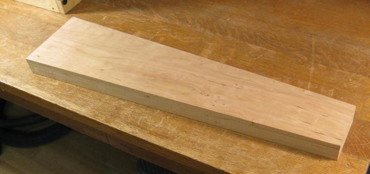
Bottom blanks ready for shaping
The next step was to make the bottom portions of the base. These were comparatively simple and just involved laminating a couple pieces to get an adequate thickness and then running them through the router a few times. This shot shows the four blanks ready to go.

Edge profile on a bottom piece
...and here is the profile after routing. The joint between the two pieces of wood is pretty evident on this piece, but the arc piece that goes on top actually hides that joint.
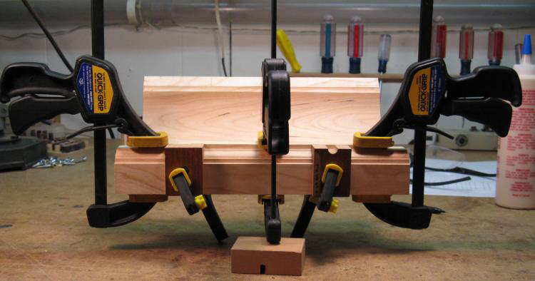
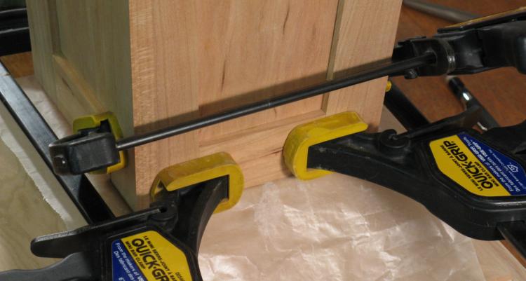
Bottom and arc forming a lasting bond
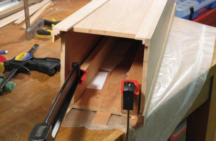
So the next step was to marry the bottom pieces with the arc pieces. I feel this is a marriage will last since the bonding involves a polyvinyl acetate emulsion adhesive with a shear strength "exceeding that of the strongest wood", seen supervising from the background. Here is one of the assemblies precariously balanced on its clamps.
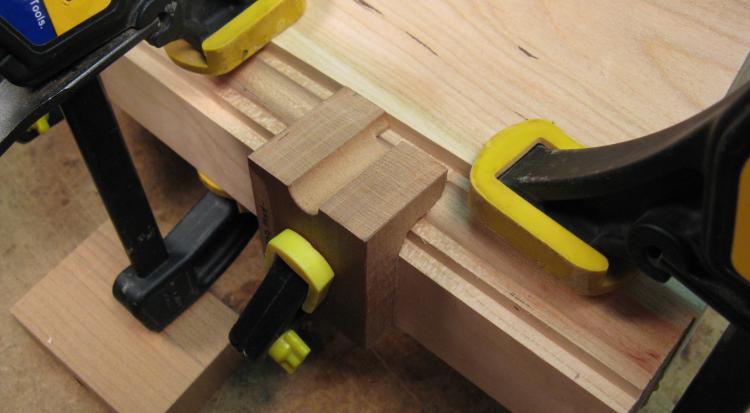
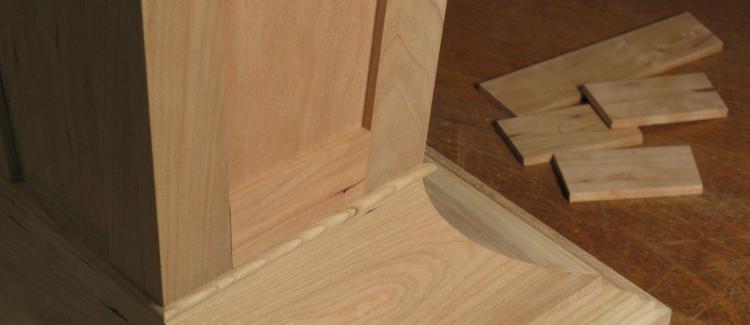
Edge guide detail
The two smaller clamps hold some guide spacers made from scrap wood (a remnant of a chair assembly test piece from 2008 if memory serves - I really gotta clear out my workshop...). These were used to position the arc the correct distance from the edge of the bottom piece.
The four bottom assemblies
Here are the four arc/bottom pieces sitting around (along with the ubiquitous bottle of glue) as as I ponder the next stage of assembly. I added the bottom foot to them to allow them to stand upright on their own and make assembly a bit easier.
To make the full base portion, I was going to need the four sections cut at very accurate 45 degree angles and equal lengths. The edges also needed to be straight and parallel. This calls for a suitable rotating-blade saw such as a table saw. Unfortunately there was over 4" of height which would call for a table saw with a 10" or greater blade - rather tough to come by. However a buddy of mine had a 10" sliding compound mitre saw that turned out to be just, just big enough (after a few noncritical pieces were removed from the saw).
Accurate mating cut concept
The conventional approach would be to do some fairly extensive angle calibrations on the saw, make some precise angle and perhaps length jigs, and then do a bunch of test cuts and measurements on scrap wood. Then if everything was good, the pieces could be cut.
I decided to bypass most of that. The approach I decided on was to cut the pieces a bit long with not-very accurate cuts, and then mount them on a jig for a second, more-precise cutting.
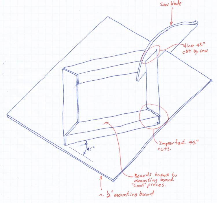
This sketch shows the concept. The circular saw cuts both mating edges at the same time, perfectly parallel. Imperfections in the 45 degree angle of the cut or the blade being slightly non-vertical don't matter much since both mating edges are still parallel. The jig allows the pieces to be precisely placed so the lengths will be very close and then the circular saw just needs to make four cuts, and the precision work is done.
Of course this shows a table saw and I'd be using a mitre saw where the blade comes over the top, but the concept is unchanged.
I decided to bypass most of that. The approach I decided on was to cut the pieces a bit long with not-very accurate cuts, and then mount them on a jig for a second, more-precise cutting.
This sketch shows the concept. The circular saw cuts both mating edges at the same time, perfectly parallel. Imperfections in the 45 degree angle of the cut or the blade being slightly non-vertical don't matter much since both mating edges are still parallel. The jig allows the pieces to be precisely placed so the lengths will be very close and then the circular saw just needs to make four cuts, and the precision work is done.
Of course this shows a table saw and I'd be using a mitre saw where the blade comes over the top, but the concept is unchanged.

One side cut to approximate length/angle
Here is one of the sections cut to length using a band saw (this cut shortened the piece from an initial experimental cut which is why the cut-offs already have the 45 degree angle on them). I used a similar concept for the "crude' cuts as for the final accurate cuts - the sections were mounted on a flat piece of MDF at the correct angle and position and then I just made a regular 90 degree cut with the saw.

The four sides assembled to check fit
Here the four sides have been cut and placed together to make sure everything aligns.
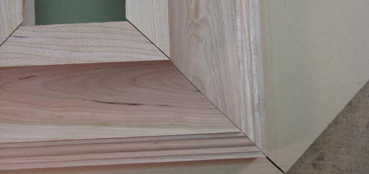
One imperfect joint
This shows one of the joints. It's kind of close-ish in an approximate ballpark-y kind of way, but I think the gaps would look pretty obvious after it was assembled.
Ready for final cutting...not
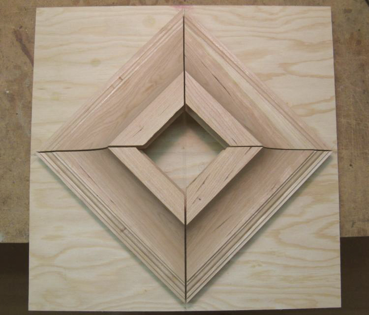
So finally the four pieces were mounted on a piece of plywood at the correct angle and spacing, ready for the edge cut.
Except, ummm, no. The assembly turned out to be a bit too wide for the reach of the saw - Arrgggg....
Except, ummm, no. The assembly turned out to be a bit too wide for the reach of the saw - Arrgggg....
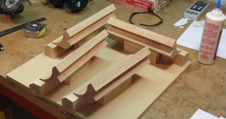
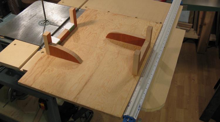
OK. Now. Pairs of sides ready to be cut.
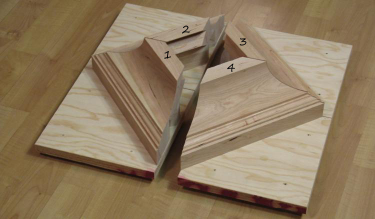
So I ended up cutting the plywood into four pieces, one with each side piece on it. Then I made four holders that each held two adjacent pieces at the proper spacing. So for sides 1, 2, 3 and 4 as shown the four holders held 1 & 2, 2 & 3, 3 & 4 and 4 & 1. This shot shows the holders with sides 1 & 2 and 3 & 4 on them (the holders are under and smaller than the main pieces of plywood so can't be seen here). Matching screw holes ensure everything aligns correctly on whichever holder it is assembled.
So then ten minutes with the saw to make four cuts and it was done (thanks Gary).
So then ten minutes with the saw to make four cuts and it was done (thanks Gary).
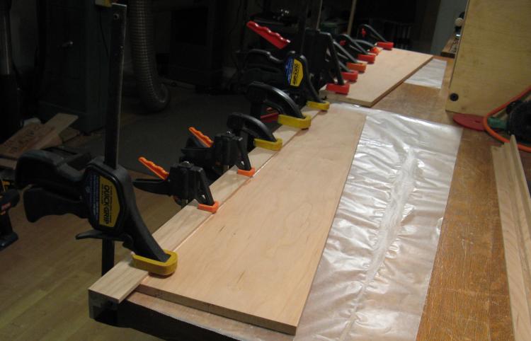
Bottom being clamped
The fit wasn't too bad, but it took a bit more tweaking of one edge with a hand plane to minimize the gaps to my satisfaction. Then it was glued and held together with a plethora of clamps as shown here.
One of the short little feet
And then some short feet were added to the corners...
(Mostly) completed bottom piece
...and the bottom was mostly complete.

Top trim pieces added
There were a couple more bits and bobs to stick on, including the trim pieces mounted on the top. They were just made from flat sections of wood with one edge being routed round. They were cut to fit and mounted as shown.
The 45s for the trim pieces weren't too much of a problem since they needed to be aligned only on the outside one-quarter inch or so, since the piece that sits on top covers the rest. I was able to get these close enough using a 45 degree miter guide on a belt sander.
The 45s for the trim pieces weren't too much of a problem since they needed to be aligned only on the outside one-quarter inch or so, since the piece that sits on top covers the rest. I was able to get these close enough using a 45 degree miter guide on a belt sander.
Completed bottom piece
And lastly a pair of guide blocks were added to properly position the middle section when it mated with the bottom. These were actually added after the middle section was complete in order to ensure accurate positioning.
Middle
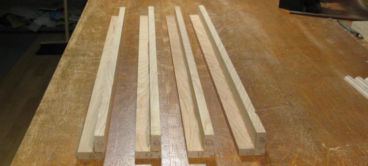
Corner parts ready to be assembled
I wanted to avoid 45-degree cuts for the long corners of the middle section too. One obvious alternative is to just use a largish piece of wood (about 1.25" square) for each of the corners, and route out the back of them to the desired thickness. However, I also wanted to be able to make use of the just-under-1-inch planks that I had available. So instead I decided to use a butt joint where the edge of one face of the assembly would be visible on the adjacent edge. I figured that I should be able to make a good joint, so with a bit of grain matching it shouldn't be too obvious.
This shows three of the corner sets, sized and ready for gluing into the corner shapes.
This shows three of the corner sets, sized and ready for gluing into the corner shapes.
Corner #1 getting glued
Now technically the corner should be a bit more than 90 degrees since the square-cross-section assembly is tapered. However, it wouldn't be much different and you probably couldn't actually see the difference. So I just went for 90 degrees on the corners.
Corner pieces assembled
Here the four corner pieces have been assembled. The planer was used to equalize the dimensions and to smooth off the glued-together surfaces.
Scribing to the cut line to prevent chips
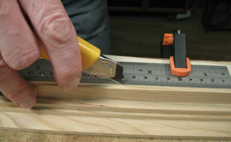
The corners were made with larger widths than what was needed to show from the outside. That provided extra strength and moved the seam a bit further from the corner. So it was necessary to thin out the edges of the parts to the 3/16" thickness that was exposed over the flat sections of the sides. This was done with a router, but depending on grain direction, the router could break out chips of wood on the edge. So to ensure the edge cut cleanly, I first scored it with a utility knife as shown here.
Yes, it looks like I got careless with the band saw, but I actually have all my finger joints - the middle one is just bent around the knife.
Yes, it looks like I got careless with the band saw, but I actually have all my finger joints - the middle one is just bent around the knife.
Thinning the edges with the router
And then the corners were run through the router table to thin each edge.
Ripping a plank for the sides
The sides of the middle section didn't need to be particularly thick so I ripped a 1" plank to make two sides. This shot shows one of the planks about half way through the ripping process on the band saw.
Sides cut to shape
After thickness planing, I marked each plank with the desired edge and cut off most of the excess just hand-guiding each piece through the band saw. The sides were more-accurately trimmed to the marked lines using multiple passes of the jointer.
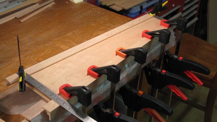
Adding the first corners to a pair of sides
So then it was time to start gluing again. The first stage was to attach on initial corner to a pair of sides as shown here.
Adding the second corner
Then a second corner was added to each side. The flat portions of the sides were made deliberately narrow to allow for some adjustment of the width (rather than count on everything being cut to exactly the right size). So the rulers at the ends were used to help position the pieces correctly.
Assembling the third side
So now there are two plain sides and two each with two corners. This shot shows one plain side (horizontal) added to the two-cornered sides (vertical). A caul is used to apply pressure along the joint with clamps at either end. Rather than using a curved caul, a straight piece was used with variable numbers of old business cards under it to maintain pressure along the length.
Adding the fourth side
And finally the fourth side was added using the same clamping technique.
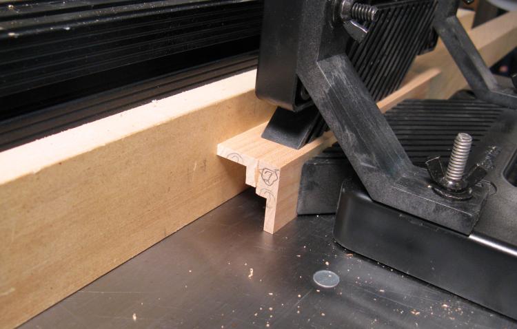
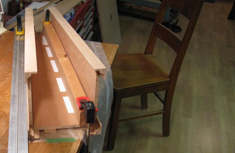
End cutting jig
As can be seen in the above picture, the pieces making up the section vary in length. The ends ultimately need to mate with flat surfaces, so they needed to be trimmed at the proper angle. I made up a jig to hold the section horizontally so that it could be run through the band saw. The jig slides against the long silver tool guide seen at the right to provide a straight cut.
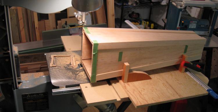
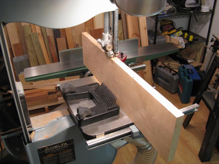
Middle piece mounted on jig
This shot shows the pedestal middle section mounted on the jig. The small end has already been cut with the thin cut-off piece visible on the metal table of the saw. Then the jig was flipped around to present the large end to the blade.
The masking tape on the end is there to hold on a sacrificial piece of wood under the bottom side (which is more visible in the next picture). This reduces the inevitable chipping that occurs on the bottom side as the teeth of the blade exit the wood. The tape also helps with the vertical side for when the blade exits there as well.
The masking tape on the end is there to hold on a sacrificial piece of wood under the bottom side (which is more visible in the next picture). This reduces the inevitable chipping that occurs on the bottom side as the teeth of the blade exit the wood. The tape also helps with the vertical side for when the blade exits there as well.
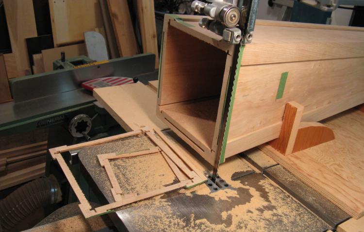
Large end trimmed off
Here the large end has been trimmed off.
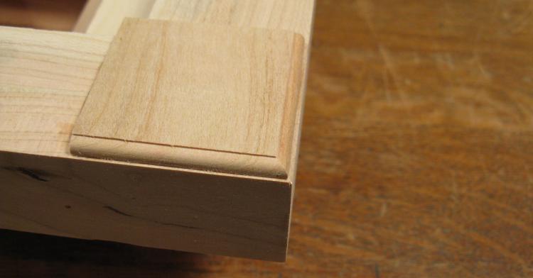
One of the trim pieces in place
Trim pieces for the top and bottom of each side needed to be added to the section. Here one of them is test-fit in place and a few others are sitting in the background.
Once again the belt sander proved useful by setting the miter to the correct angle and tweaking the length of the trim pieces to fit correctly between the slightly-tapered edges.
Once again the belt sander proved useful by setting the miter to the correct angle and tweaking the length of the trim pieces to fit correctly between the slightly-tapered edges.
Trim pieces being glued on
And here the bottom trim pieces are being glued on.
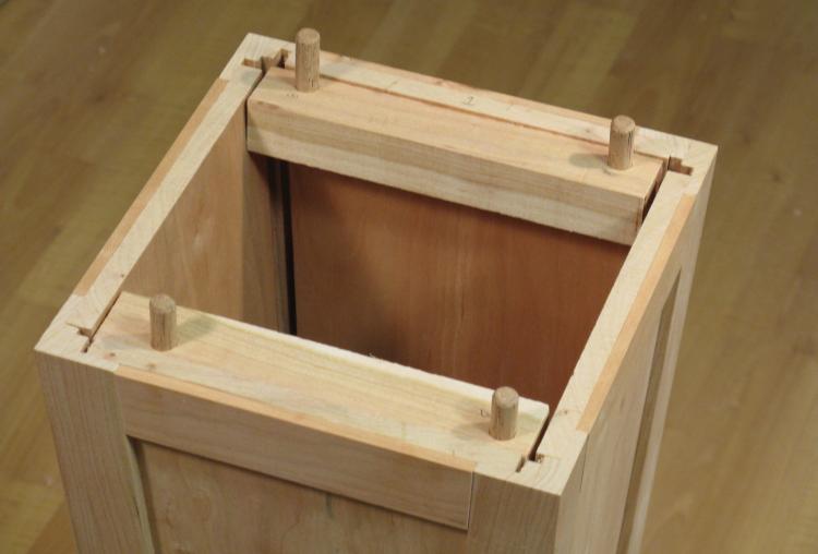
Guide pins to mate with top section added
Finally a couple sections were added at the top to hold guide pins. These wood pins extend into mating holes in the top section to ensure proper alignment.

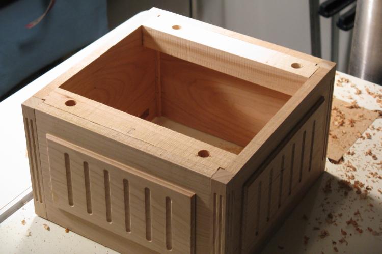
Middle section complete
And here the middle section is complete.
Top
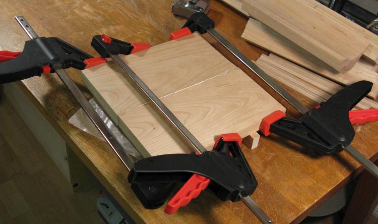
Gluing up the top surface
The top actually consists of two parts; the tabletop section and the square "box" section.
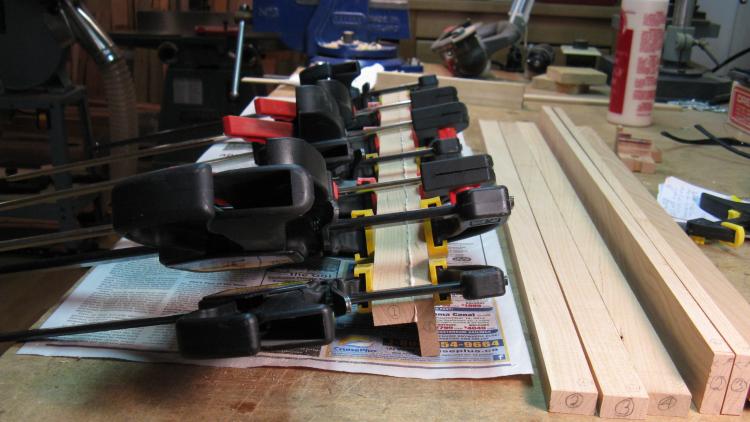
The tabletop was made first and it was pretty straightforward. I needed to laminate a couple planks edge-to-edge to get the width I needed, so after some selection, trimming and jointing, this picture shows them being glued together.
Note the wood pieces to the side. Yes, those are part of the base which was described as being completed earlier. This description was done in nice sequential order, but the same can't be said for the fabrication of the pedestal. A sharp eye will be able to spot numerous "anachronisms" in the photos.
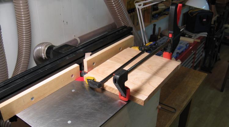
Routing the edges
The router was used to shape the top edges. Here the end-grain portion is being run through, with some scrap wood clamped on to prevent chipping at the ends.
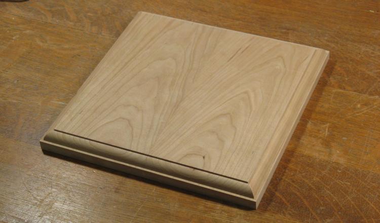
Top surface complete
And a bit of sanding and Bob's yer uncle.
So next up is the box portion of the top. To avoid the dread prospect of more 45 degree angles I decided to make decorative corners and just butt the sides up to them.
So next up is the box portion of the top. To avoid the dread prospect of more 45 degree angles I decided to make decorative corners and just butt the sides up to them.
Box sides
Here are the four walls of the top box portion, not yet trimmed for length. Two of these received routed notches on the back side to accept some clamps to hold on the top.
Corner pieces
And four corner pieces were made, each being just square cross-section shapes.
Routing the corner pieces
The corner pieces had some decorative verticals routed in as shown here. The wood seen at either end on the router table here are stops to ensure consistent routed notch lengths.
This was a pretty small detail to route, so I used a Dremel bit rather than a "proper" router bit. I had to use a previously-made adapter to fit 1/8" bit shafts in the 1/2" collet of the router.
This was a pretty small detail to route, so I used a Dremel bit rather than a "proper" router bit. I had to use a previously-made adapter to fit 1/8" bit shafts in the 1/2" collet of the router.
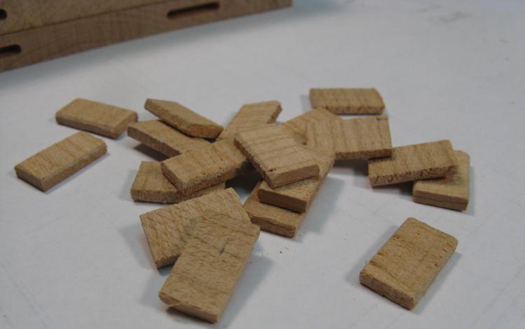
"Crackers" for joining box pieces
For a bit more strength in the butt joints, I thought I'd use biscuits, but the pieces were too small for cabinetry-sized wood joining biscuits. So I just made some small cherry biscuits (or perhaps crackers would be more appropriate given the shape). These were given a bit of a squish in a metal-jawed vise to add some texture to the outside for better glue adhesion (which doubtless made absolutely no difference, but they did look more like the professionally-made biscuits, which I found satisfying).
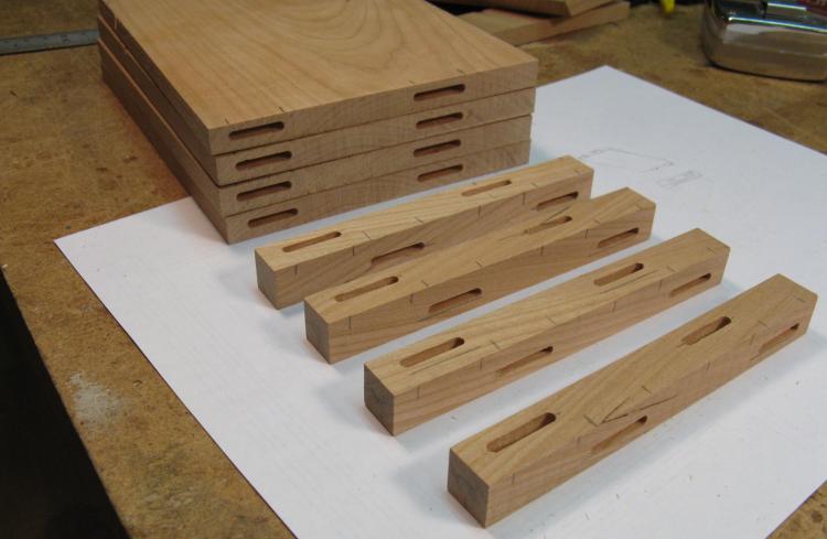
Sides and corners with slots for "crackers"
The walls and corners have matching slots for the "crackers". Given the small size of the corners, the slots on adjacent edges would have intersected, so I offset slots on alternate edges to avoid any issues that might have caused.
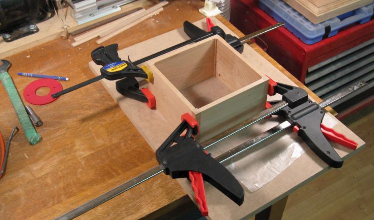
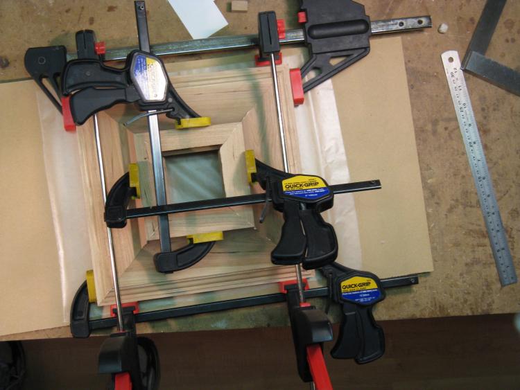
Clamping the box for gluing
So then the basic box was glued together. I started by attaching two corners to each of two opposite walls, and then as this photo shows, the other two walls are added between them.
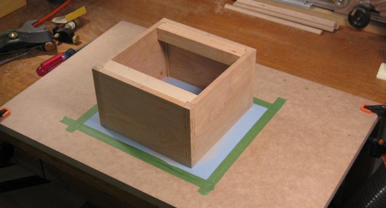
Flattening the top side with sandpaper
Here the box portion is together and has had two sections of wood added that will be used to receive the alignment pins from the middle section.
The top of the box needs to be quite flat for the tabletop to sit on it with minimal gaps, and since my gluing wasn't quite perfect, here the box is getting the top side levelled using sandpaper on a flat piece of MDF.
The top of the box needs to be quite flat for the tabletop to sit on it with minimal gaps, and since my gluing wasn't quite perfect, here the box is getting the top side levelled using sandpaper on a flat piece of MDF.
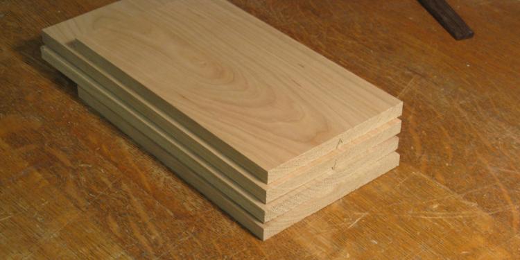
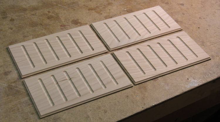
Blanks for the decorative panels
With the basic box done, it was time to add the decorative bits.
First up was the incised panels, one per side. The four blank pieces are shown here.
First up was the incised panels, one per side. The four blank pieces are shown here.
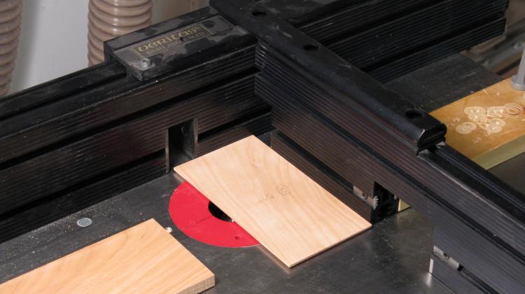
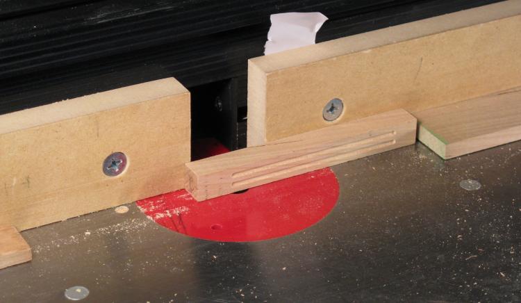
Routing the panels
And back to the router to make the circular-section details on the panels. Here a right-angle sled is used to push the piece past the bit, with the blocks of wood acting as stops to define the length of the routed slots.
Panels done
The panels were completed by adding a small radius to the edges.
Panels glued on
In this shot (with the box upside-down on the drill-press table), the panels have been glued on and the guide holes have just been drilled.
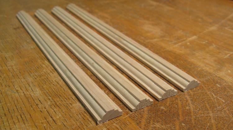
Shaped trim pieces ready to go
Next up is a narrow skirt of trim that covers the middle-to-top joint. Some thin strips were cut to size, routed to shape in a few passes and then cut to length.
Of course these require 45 degree cuts on the final installation, but like the other trim pieces above, the belt sander with a 45 degree miter guide was used on the ends.
Of course these require 45 degree cuts on the final installation, but like the other trim pieces above, the belt sander with a 45 degree miter guide was used on the ends.

Clamping & gluing the trim pieces
Here the narrow trim is glued onto the bottom edge of the top section with a smorgasbord of clamp types. The width of the middle section was adjusted to ensure it fit inside the trim.
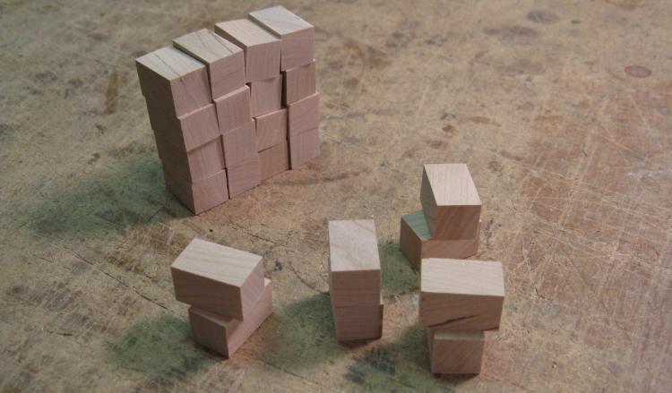
Pile 'o dentils
The blocks under the tabletop portion are called dentils. These were simply cut to size and sanded. The four sets of two blocks in front will be assembled into right-angle pieces to fit on the corners.
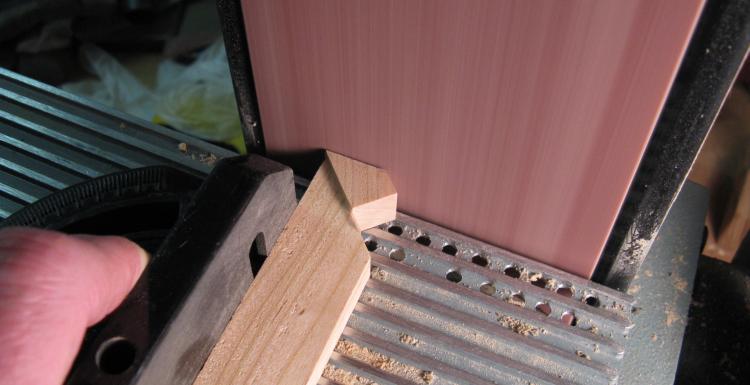
Adjusting angle and length on a corner dentil
Here one half of a corner dentil is being adjusted for length. The wood is taped to a 45-degree jig on the belt sander.
Dentils being glued on
Dentils are being glued on to the box portion in this shot. I just used an elastic band to hold them in place. They could also have been attached to the tabletop instead, but I was concerned about seasonal expansion stressing the joints.
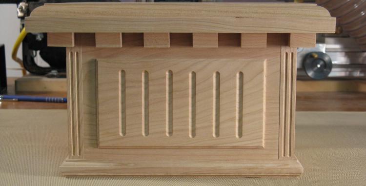
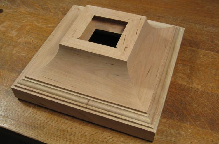
Top portion complete
This shows one face of the completed top piece with the tabletop in place as well.
Assembly Bits

Tabletop clamps
There are a few loose pieces to be made that were used for assembly of the pedestal;
I usually use clamps like these to hold on table tops. They allow for seasonal expansion of the top (most significant in the across-the-grain direction). I'm not sure if the 10" size of this particular top would be a problem, but it seemed prudent to include them and prevent potential glue-joint failures a few years down the road.
I usually use clamps like these to hold on table tops. They allow for seasonal expansion of the top (most significant in the across-the-grain direction). I'm not sure if the 10" size of this particular top would be a problem, but it seemed prudent to include them and prevent potential glue-joint failures a few years down the road.
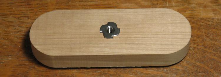
Top clamp
As can be seen in the plan at the top of this page, a threaded rod (5/16") was used to hold the three main assemblies together. This piece includes a T-nut to accept the rod and holds down the top section. I had originally planned to have this as a separate piece that would need to rotate into position, which accounts for the rounded ends. Ultimately I just glued it into place.
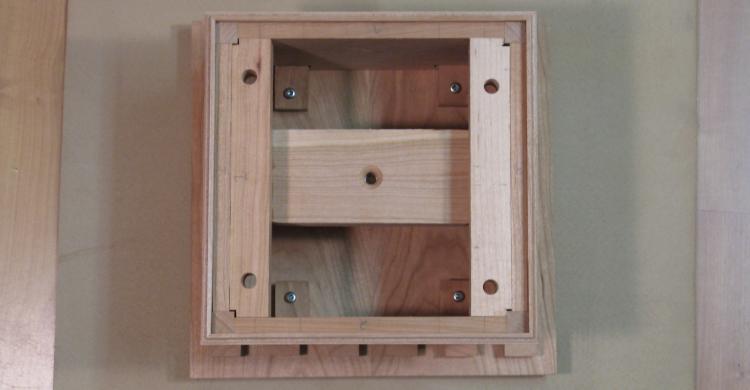
Top with assembly clamp
Here the underside of the top section is shown with the clamp piece from above in place. In this shot it's also possible to see the four clamps which hook into milled slots in two of the sides and screw into the tabletop.
Bottom wood "washer"
The bottom has a large square hole in the center so it needed something to hold the nut for the threaded rod. I thought a bit more weight in the base might also be a good idea so I used a fairly sizeable piece of 1" wood with a recess for the metal washer I was planning to use.
Assembly
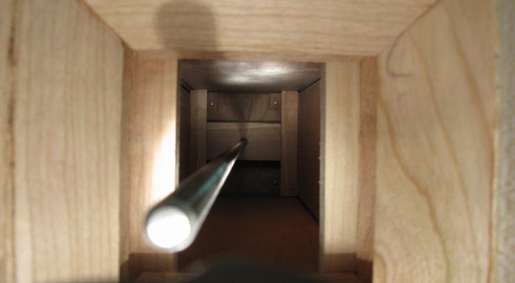
Threaded rod in place
The assembly was somewhat anti-climactic since it was quite simple. It consisted of stacking the bottom, top and middle sections, inserting the threaded rod, and adding a washer and nut.
Here the pieces are assembled and the rod has been threaded into the T-nut in the top section. This shot looks from the bottom to the top.
Here the pieces are assembled and the rod has been threaded into the T-nut in the top section. This shot looks from the bottom to the top.
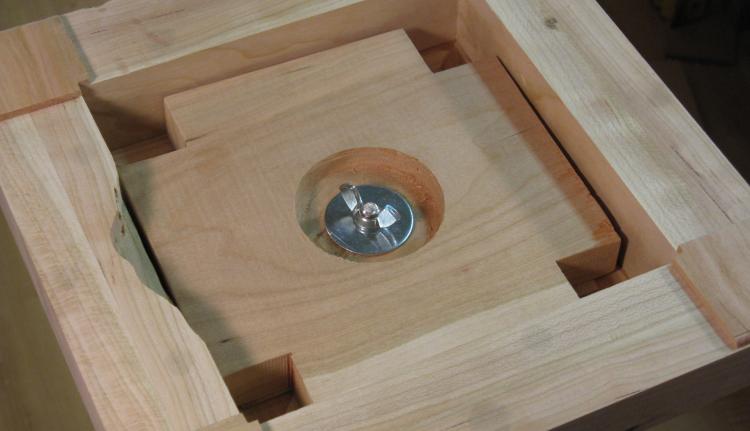
Nut and washer on the bottom
A large washer and a wing nut were used on the threaded rod to hold everything together.
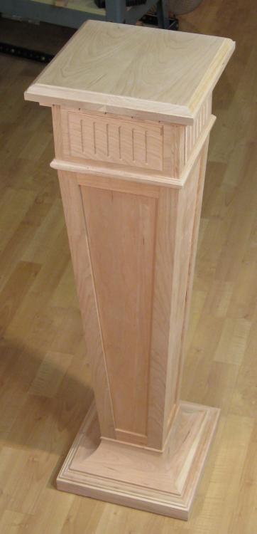
Pedestal fully assembled
And the pedestal is fully assembled.
Of course it still has to have the finish applied. Ironically, that needs to be done in pieces so apart it comes again.
Of course it still has to have the finish applied. Ironically, that needs to be done in pieces so apart it comes again.
Applying finish
In order to prevent warpage it is best to have the same finish on both sides of a plank (like those that make up the middle and top sections). So both the inside and outside of each piece was varnished with the same number of coats (three in this case).
I used my favorite Miniwax Wipe-On Poly (applied with foam and bristle brushes), and sanded with #0000 steel wool between coats. A vacuum with a brush was used to remove steel wool particles and finish residue before the next coat.
I used my favorite Miniwax Wipe-On Poly (applied with foam and bristle brushes), and sanded with #0000 steel wool between coats. A vacuum with a brush was used to remove steel wool particles and finish residue before the next coat.
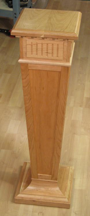
Finished
Unfinished
After finish and reassembly the pedestal looks much more cherry-coloured.
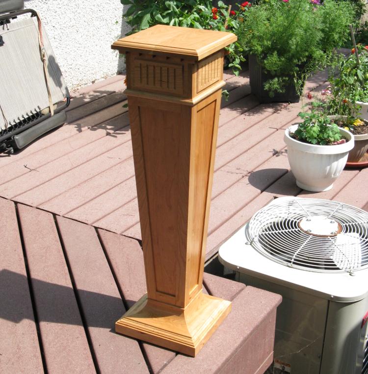
In the sun
As explained on the main page, I put the pedestal out in the sun to darken the wood up a bit before it was moved to the sunroom (which despite its name wouldn't help this piece much since it would be in a shadowed corner).
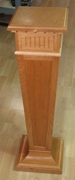
Finished and tanned
Finished
A couple days in the sun (only got rained on once) and it darkened up nicely.


