The friend this viewer belongs to is a photography buff and includes among his endeavours stereoscopic photography and holography. This particular viewer was built to view stereoscopic 35mm slides, which are pairs of photos taken laterally-offset from each other to produce a stereoscopic image. The viewer had custom-turned plastic lens holders but just used an old Radio Shack project box for the enclosure. The inside content included a slot assembly for the slide and a translucent window at the rear to back-light the slides. In operation it would be held up to a bright light (outside is best) to illuminate the image. I was interested in making a shaped wooden enclosure and he passed this viewer on to me for "woodification".
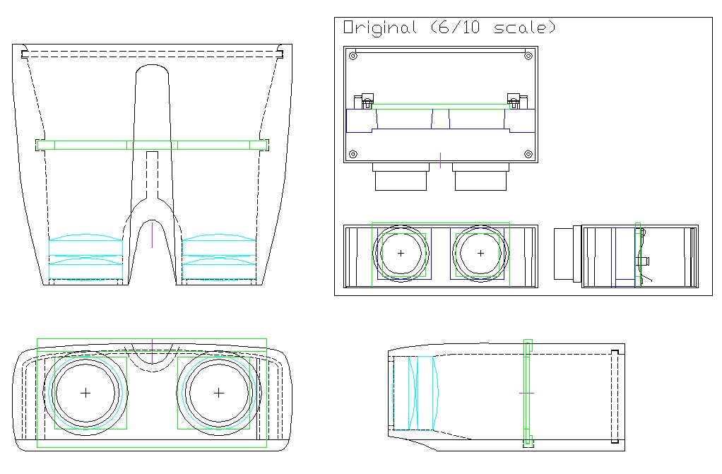
The plan, new and old
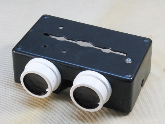
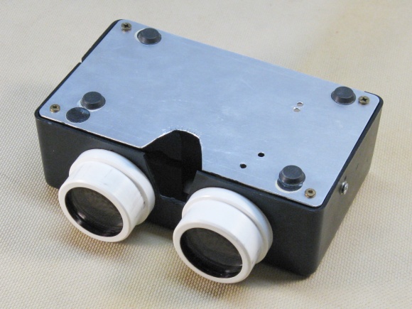
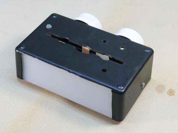
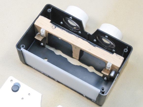
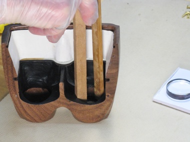
This array of shots show the original viewer. It includes custom-turned holders for the lenses attached to a plastic project box. Internally a wood frame supports a slot mechanism that guides and holds the slide while light enters from the rear wall which includes a diffuser for even back-lighting of the slide. An aluminum sheet seals the bottom of the viewer.
Mostly disassembled
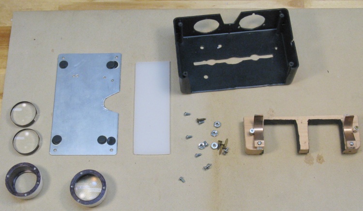
This is the "exploded" photo of the viewer. The pair of lenses has been extracted from one of the holders while the other still has the lenses installed.

Starting to carve a model
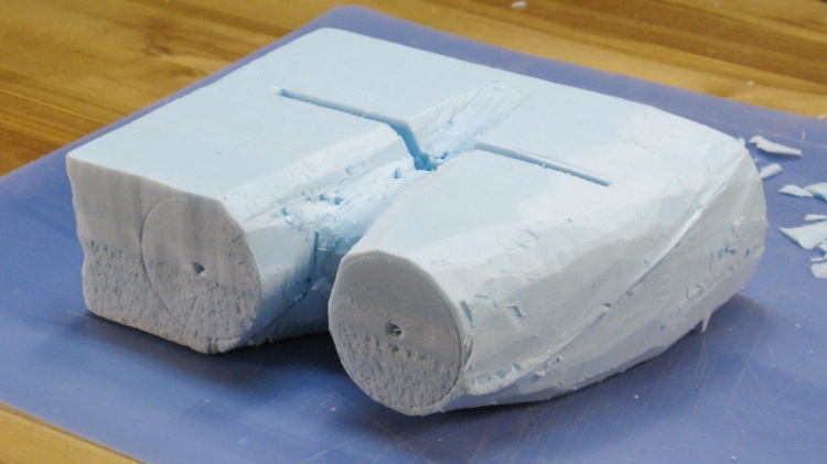
I thought I'd carve a quick 3D model of the viewer to get a better idea of what it would look like.
I used a small piece of 2"-thick Styrofoam SM, sharpened up a little-used paring knife into a styrofoam-cutting knife (I don't think you'll miss it Sue), and got slicing.
Here I'm starting with the inter-eye dip, a feature that will make it easier to grip the slide.
I used a small piece of 2"-thick Styrofoam SM, sharpened up a little-used paring knife into a styrofoam-cutting knife (I don't think you'll miss it Sue), and got slicing.
Here I'm starting with the inter-eye dip, a feature that will make it easier to grip the slide.
A finely-crafted 3D model
A bit of carving got the model to this point.
The inter-eye dip looked OK, the space for the viewer's nose seemed adequate, the shape was largely what was evisioned and I had even carved the "crease" in one of the sides to see what that would look like (OK, maybe not that great when rendered in styrofoam).
Everything seemed to look OK so then it was time to do it for real.
A nice 2"-thick piece of walnut
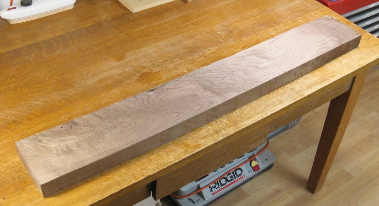
I had decided to use walnut for the viewer body. Fortunately I had a nice piece of 8/4 walnut on my shelves which would work just fine.
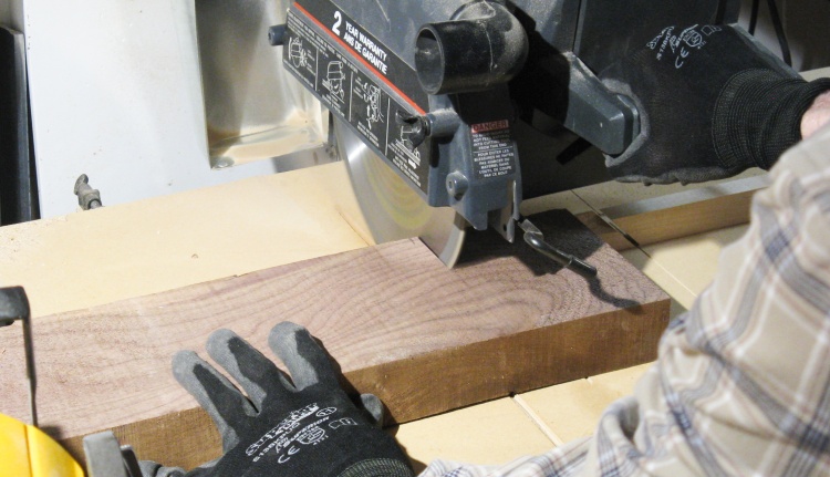
Cutting off a viewer-length piece
Step one was to chop off a viewer-length piece.
The viewer would consist of a hollow body forming the front, sides and top and there would be a separate screw-attached flat base. This piece was used for the main body.
The viewer would consist of a hollow body forming the front, sides and top and there would be a separate screw-attached flat base. This piece was used for the main body.
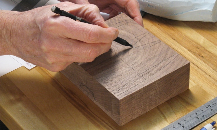
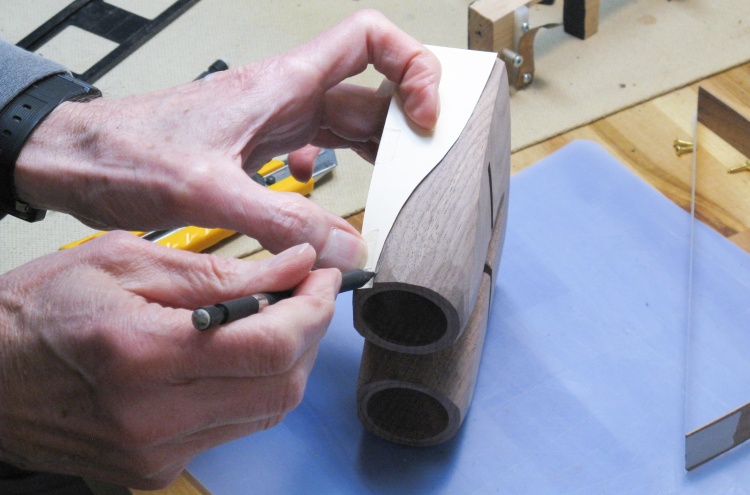
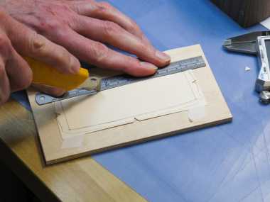
Marking the contours
I then traced the outline onto the bottom of the body to guide the hollowing process.
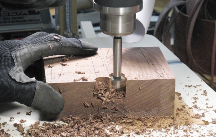
Starting on the coarse hollowing
I used a 3/4" Forstner bit to do the bulk of the hollowing. It makes quick work of wood removal but leaves very rough surfaces behind.
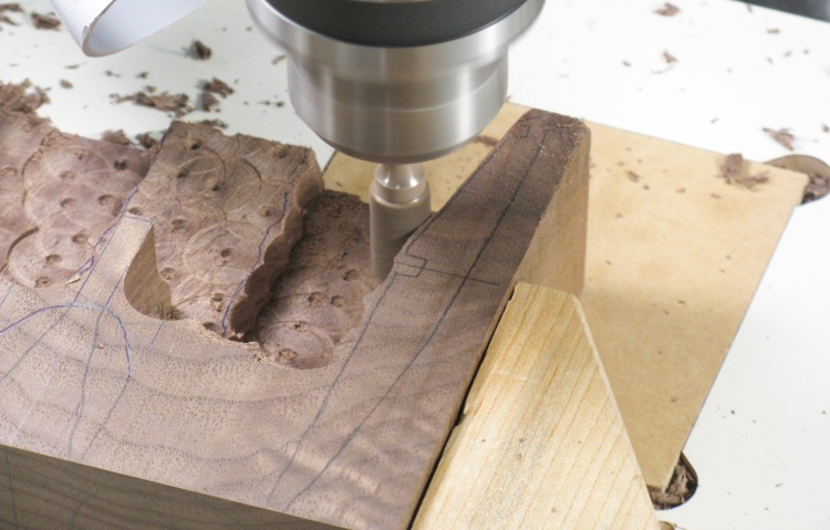
Starting to smooth off the rough-cut surfaces
And here's a shot of those rough surfaces. To even them out and get closer to the finished wood thickness, I switched to a fluted cutter. In this shot, I'm cleaning up one of the walls.
I used a big wooden clamp to help hold the body, and it was just maneuvered by hand to guide the wood removal.
I used a big wooden clamp to help hold the body, and it was just maneuvered by hand to guide the wood removal.
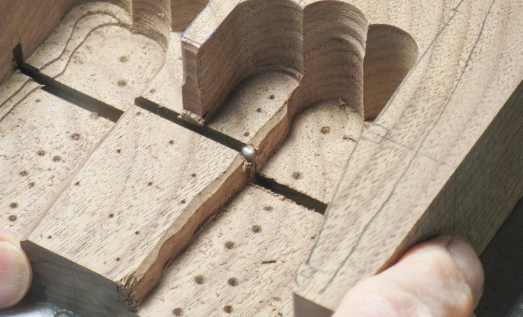
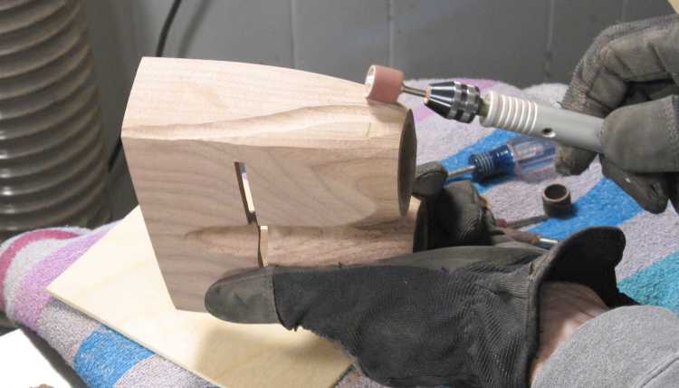
Milling out the slot for the slide
A slot for slide insertion was milled out using the router table.
Unfortunately the 1/8" bit needed for the slot wasn't long enough to get all the way through, so that was switched over to a 1/8" fluted Dremel bit to get through the high parts as shown here.
Unfortunately the 1/8" bit needed for the slot wasn't long enough to get all the way through, so that was switched over to a 1/8" fluted Dremel bit to get through the high parts as shown here.
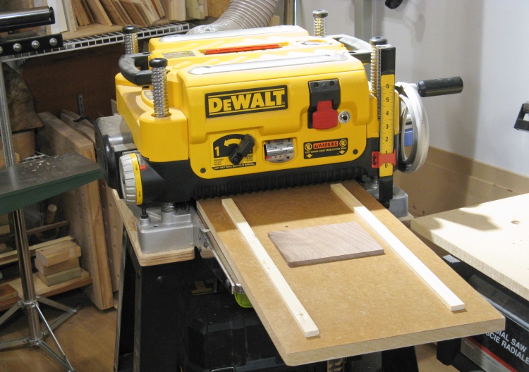
A blank for the base about to enter the planer maw
The other piece needed for the viewer is the flat base. I cut a suitable piece of walnut to a bit thicker than the finished size.
It needed to be around 0.2" thick and here the planer is about to "make it so".
It needed to be around 0.2" thick and here the planer is about to "make it so".
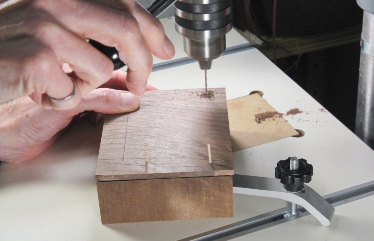
Drilling base screw holes
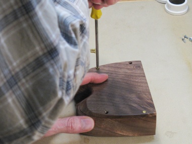
I planned to shape the body and base together so the first order of business was to screw them together.
In this photo I'm drilling pilot holes for the screws, going through both pieces at once to ensure the holes are accurately aligned.
In this photo I'm drilling pilot holes for the screws, going through both pieces at once to ensure the holes are accurately aligned.
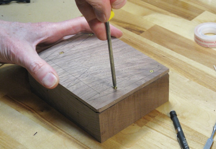
Screwing down the base
Then after clearance holes were drilled and countersinks added, the 1/2" brass screws were installed.
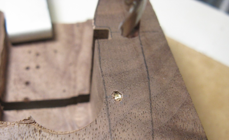
Doh! Twisted the head of the screw off!
Unfortunately one of the pilot holes wasn't deep enough and when trying to drive the screw deeper, the head twisted off the soft brass screw. That's gonna need to be fixed.
I hoped I could just drill out the screw using the standard twist-drill bit as seen here.
I hoped I could just drill out the screw using the standard twist-drill bit as seen here.
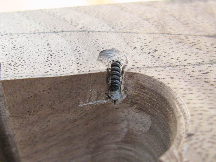
Screw pried out sideways
And much to my complete lack of surprise, that didn't work; the bit just slipped off the screw body and drilled the wood.
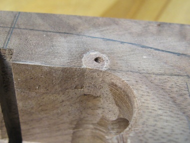
So then it was on to Plan B: The screw was close to the edge so I just ground away the wood next to the screw and pushed the screw out sideways. This shot shows the resulting cavity.
So then it was on to Plan B: The screw was close to the edge so I just ground away the wood next to the screw and pushed the screw out sideways. This shot shows the resulting cavity.
That process didn't leave a very nice-looking hole so the next step was to make a nice hole. I used a 1/4" forstner bit to drill a clean hole that intersected the side. I then turned a small piece of walnut with the correct grain orientation on my small lathe to 1/4" diameter. That was glued into the nice hole and then it was cut flush, sanded smooth and re-drilled for the screw, of course making sure the pilot hole was deep enough this time...
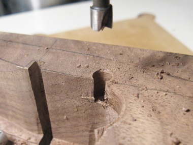
Nice clean 1/4" hole
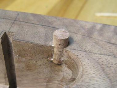
Adding a 1/4" plug
Trimmed & re-drilled
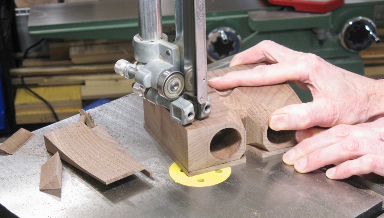
Ready to drill a 36mm lens hole
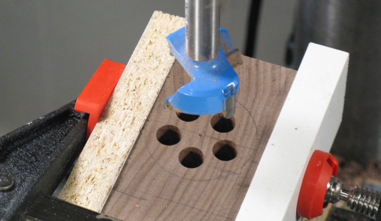
The lenses were 36mm in diameter and I needed a matching hole size. I used a 36mm Forstner bit but a test hole on a scrap showed that it didn't much like going into walnut end grain - it took a lot of force and produced a lot of vibration.
So to smooth the process out, I first drilled five smaller holes so there was less end grain to contend with, plus the holes aid with chip removal. I also clamped the sides of the viewer for extra strength since the walls after drilling would be fairly thin.
So to smooth the process out, I first drilled five smaller holes so there was less end grain to contend with, plus the holes aid with chip removal. I also clamped the sides of the viewer for extra strength since the walls after drilling would be fairly thin.

Doing a bit more inside shaping
After the lens holes have were drilled, a bit more milling was done to reduce the thickness of the top. The resulting terraced surface will be smoothed out later.
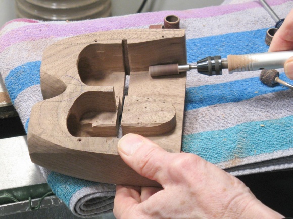
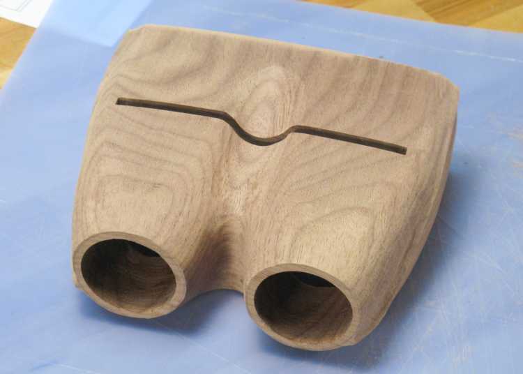
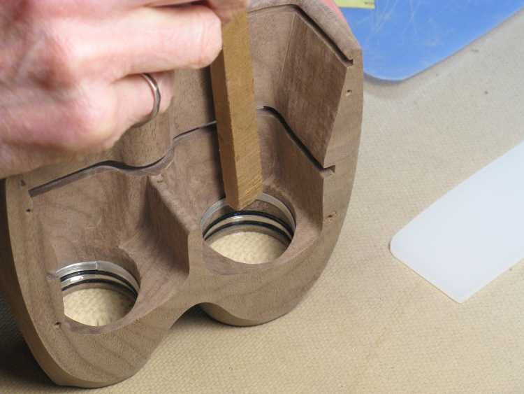
Cutting out the nose slot
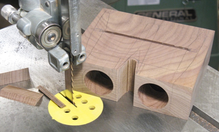
With coarse hollowing of the inside done, it was time to start on the outside shaping.
The first step was to cut out this between-lens section, which would save a bunch of grinding.
The first step was to cut out this between-lens section, which would save a bunch of grinding.
Starting the outside shaping with a coarse rasp bit
Then it was on to the actual shaping. I started by forming the center dip using a coarse rasp bit chucked into the lathe.
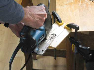
Cutting the curved sides
Next step was to cut the curved sides of the body and base. That was done using the bandsaw as shown here, leaving on an extra 1/8" or so of thickness to provide material for the protruding crease.
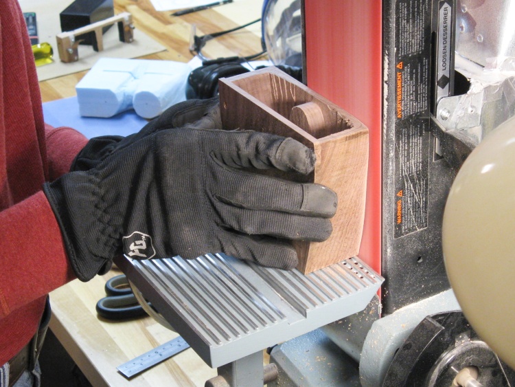
Rounding off the top on the belt sander
The top was to have a curved side-to-side profile and that curve was formed using the belt sander.
Then there was a bit more shaping here and there. These shots show some drum sanding on top to remove the deep scratches left from the rasp bit, and a smaller drum sanding down the inside terraces.

Some finer sanding outside
...and inside
Making a cardboard pattern for side creases
To mark the side creases I cut a cardboard pattern out of light cardboard (specifically a file folder).
Marking the sides
...which was then used as an aid to mark the two sides.
Shaping a side around the crease
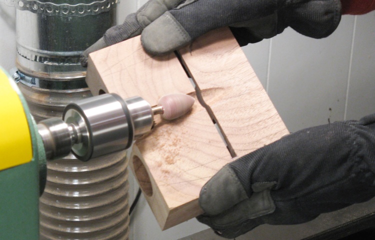
Then I started the side shaping which involved removing most of that extra 1/8" around the crease, and imparting a top-to-bottom curve as well.
In this shot I'm just starting to define the crease using a small sanding drum.
In this shot I'm just starting to define the crease using a small sanding drum.
The coarse shaping is mostly done here
So then a bunch of drum and belt sanding later, most of the body shaping was done.
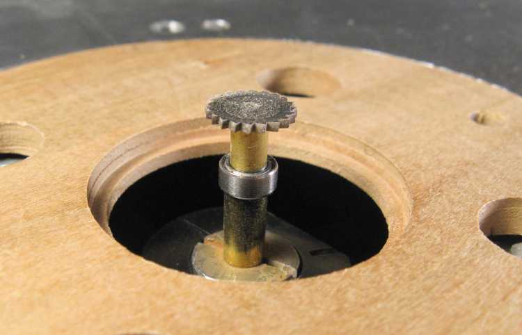
Cobbled-together slotting bit on router table
The viewer needed a slot at the rear to hold the diffuser. After some puzzling as to how best to do that, I finally ended up with this arrangement using a little "buzz saw" bit which I modified to include a bearing to ride against a pattern.
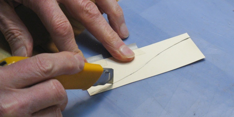
The pattern for the diffuser slot was essentially the rear opening shape, but a bit smaller. I made a little cardboard pattern first and then attached it to a piece of 1/4" Baltic birch plywood and cut through the pencil lines with a knife to mark the plywood. The hole in the plywood was then cut out and sanded;
Marking slotting pattern onto plywood
Cutting out the pattern
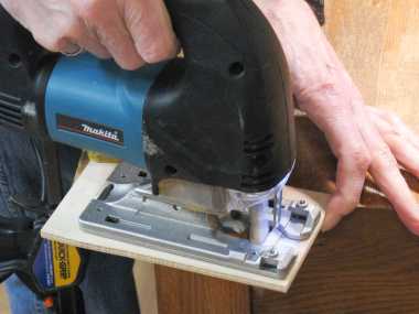
Sanding using the "sanding blade" in jigsaw
Cutting the diffuser slot on the router table
Then the viewer body and base were taped to the plywood pattern and the slot cut on the router table (which of course took much less time than making the pattern). The slot was cut using three or four different bit heights since it needed to be wider than what a single cut of the bit would produce.
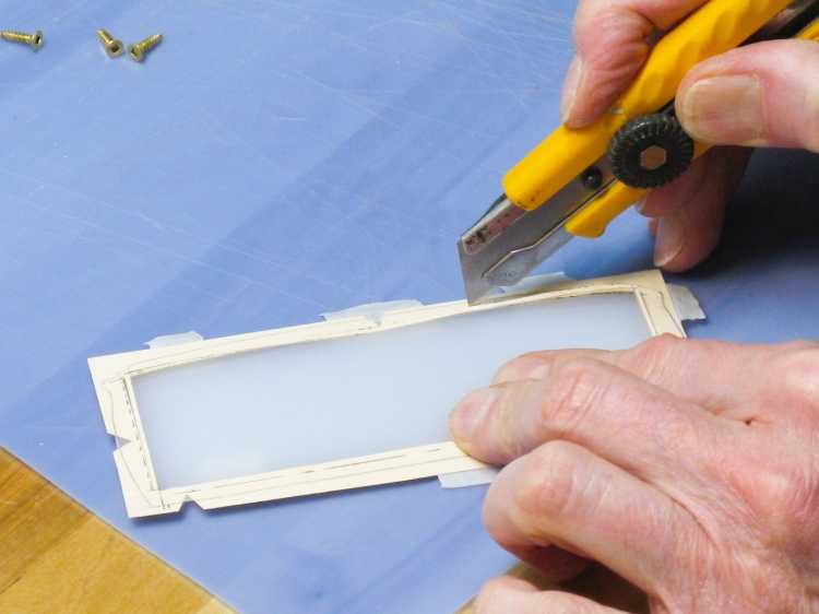
Using pattern to mark the diffuser
I then used the cardboard pattern (with appropriate lines added) to mark the shape of the diffuser plastic as shown here.
Checking fit of diffuser in slot
The diffuser was sanded down to the scribed lines on the belt sander and then deburred with a knife. In this shot I'm doing a test fit into the viewer slot.
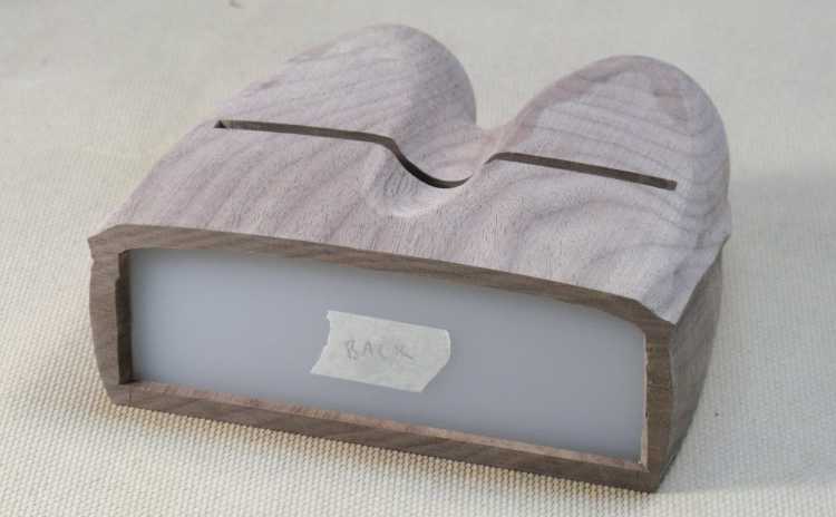
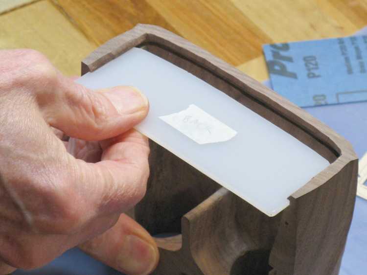
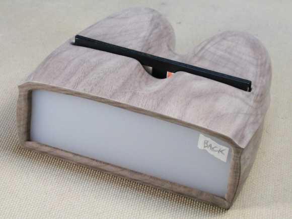
Rear view with diffuser in place
The diffuser is in place in this photo.
A couple of aluminum lens-spacing rings
Each eye has a pair of lenses. I didn't want them to touch so I made some spacers that would keep them about 0.02" apart. I ended up making the spacers from aluminum sheet, cutting off strips with a sharp knife and bending them to fit into the lens holes in the viewer.
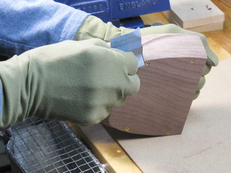
And then the hand sanding starts
And then the hand sanding of the body got underway. That was started at 150 grit and went to 600 grit which essentially eliminates any visible scratches.
Since the lens holes had been drilled from the front, I needed to add something to hold the lenses in. The plan was to make thin wooden rings that would be glued into place. They would be 36mm outer diameter to fit in the lens holes and about 33mm inner diameter with the grain direction running from front to back to match the viewer body. I started with an old walnut test piece from a side table made years ago and turned a hollow cyllinder of the appropriate dimensions, then just cut it into slices to get rings.
Walnut scrap to use as lens ring blank
Turning hollow cylinder
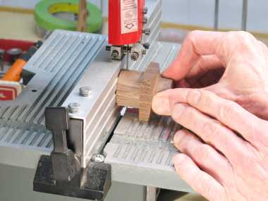
Cutting the rings from the cylinder
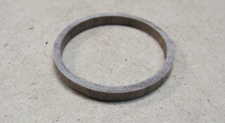
One of the lens-holding rings
This is one of the rings, ready to install.
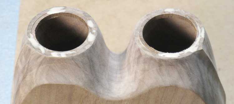
Lens rings glued into place
The rings were just glued in, flush with the front of the eyepieces.
Rounding and sanding the openings
Once the glue was dry, the front was sanded even and then the corners rounded with sandpaper strips.
At this point I also rounded the other still-sharp edges including the rear of the viewer and the slot for the slide.
At this point I also rounded the other still-sharp edges including the rear of the viewer and the slot for the slide.
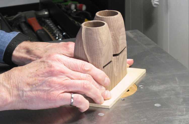
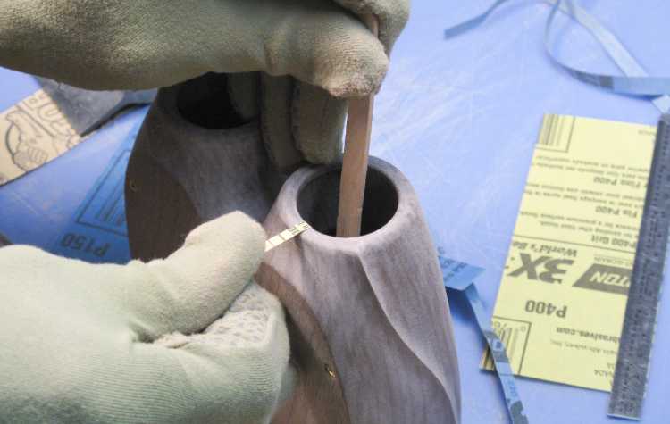
Assembling for dress rehersal
That was pretty much it for the woodworking so I assembled the viewer to make sure everything worked together. In this shot I'm inserting a ring to hold the lenses in place.
These photos show the front and rear views, complete with a slide in place.
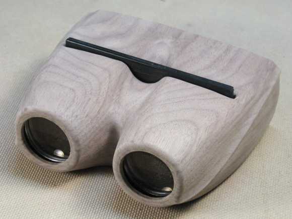
Front view with slide in place
Rear view
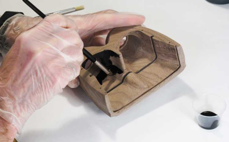
Inking up the lens-to-slide section
Then it was finishing time.
The viewer came back apart and I used a small brush to apply black india ink to the lens-to-slide area to reduce reflections.
The viewer came back apart and I used a small brush to apply black india ink to the lens-to-slide area to reduce reflections.
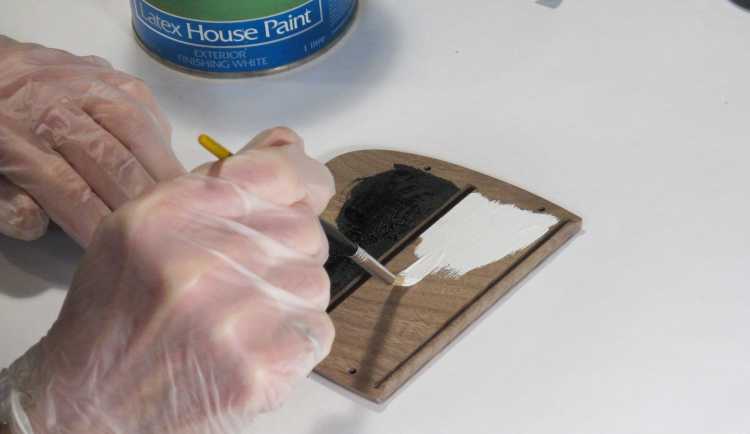
Painting the slide-to-diffuser section
The slide-to-diffuser area was painted with a nice white external latex to enhance light transfer from the rear.
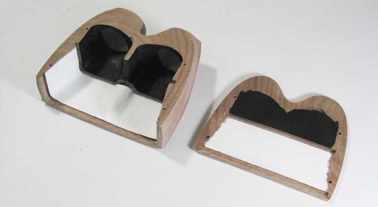
The two pieces black 'n whited
This shows the two pieces after the ink and paint stage.
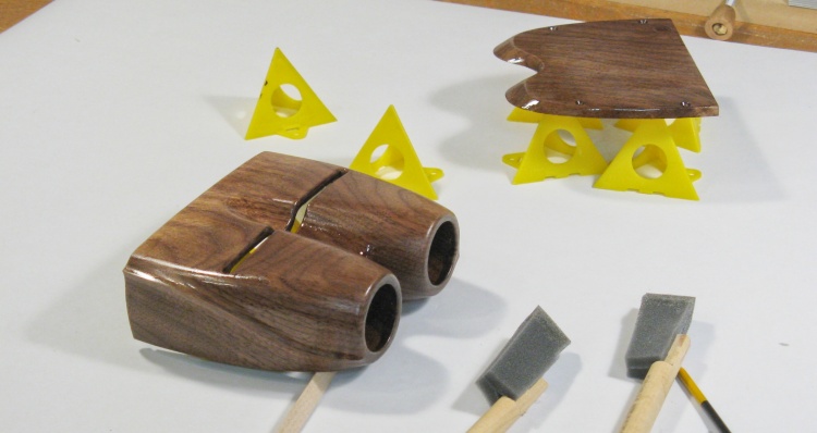
First coat of varnish installed
The walnut darkened up nicely after the first coat of varnish was applied. I used my normal Satin Fast-Drying Polyurethane and applied three coats with steel-wool sanding between coats.
Lee Valley Tools delivered 2" foam brushes instead of the 1" version that I had ordered. The 2" was really too large to do the viewer, so I cut them in half which is why the brushes are rather lopsided in this shot.
Lee Valley Tools delivered 2" foam brushes instead of the 1" version that I had ordered. The 2" was really too large to do the viewer, so I cut them in half which is why the brushes are rather lopsided in this shot.
After the last coat of varnish had dried (for two or three days to eliminate any danger of the pieces bonding together) I assembled the viewer. After cleaning, the lenses were inserted into the viewer with a blackened aluminum ring to separate the two lenses in each eyepiece. Another ring followed to hold them in place and that one was tacked down with some latex adhesive. The diffuser was inserted into its slot and then the base was attached with the four screws - and that was it.
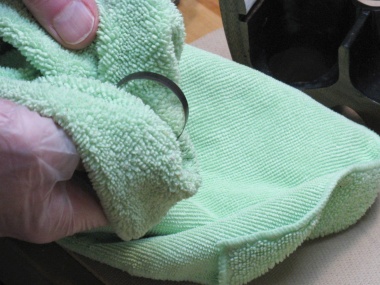
Cleaning the lenses
Installing lenses
Attaching base
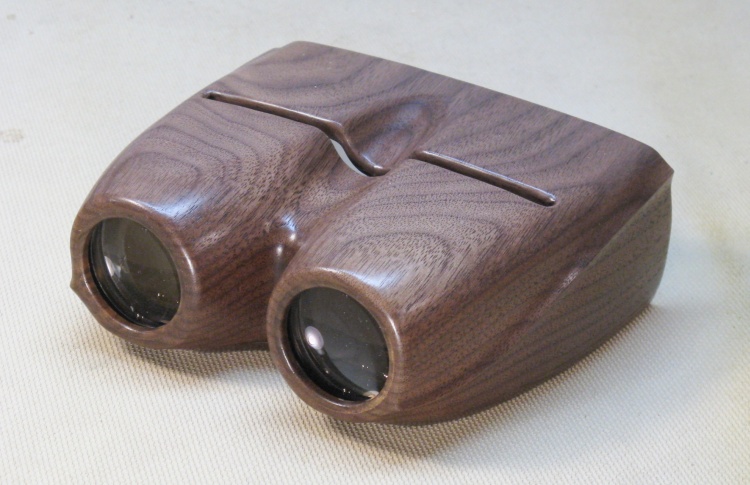
Front view of completed viewer
Front view.
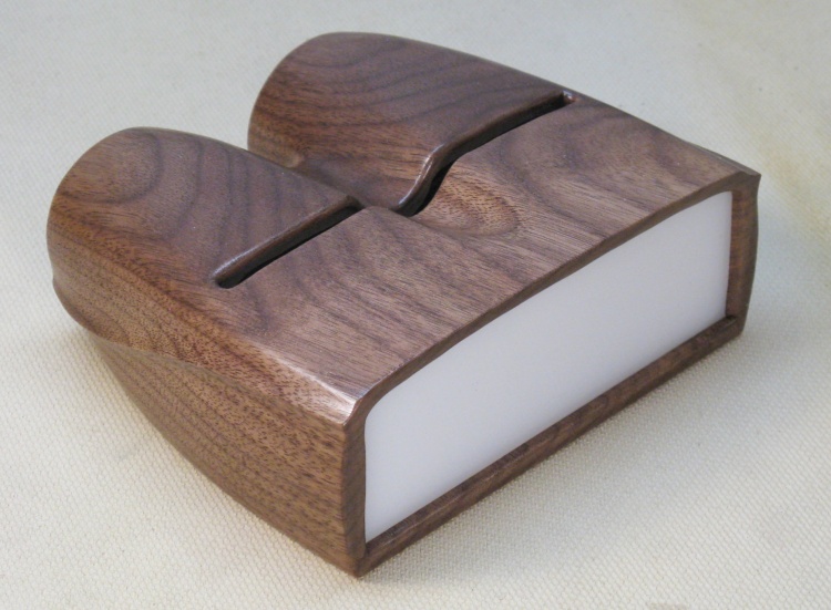
And rear view
Rear view.


