As mentioned on the main page, this table fits over the arm of a chair and is modelled on a commercial version. That one was actually made to fit a few different arm widths but was a pretty large item to store when not in use. To get around that problem, this one was made to fold down into a more compact package for storage. It fits only a single arm width but that wasn't a problem since that was all I needed.
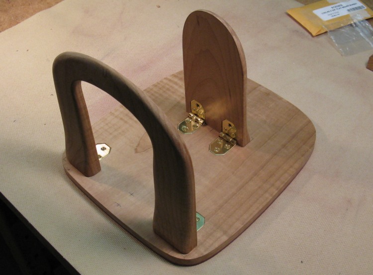
The "legs" are spaced just right to squeeze the arm a bit and provide some friction. To apply the pressure, the legs needed to be hinged on the inside so they were prevented from opening further than the designed 90 degrees. To be able to fold-in both sides, the legs needed to be non-interfering so the outside one is narrow while the inside one is an open shape that fits around it.
The "legs" are spaced just right to squeeze the arm a bit and provide some friction. To apply the pressure, the legs needed to be hinged on the inside so they were prevented from opening further than the designed 90 degrees. To be able to fold-in both sides, the legs needed to be non-interfering so the outside one is narrow while the inside one is an open shape that fits around it.
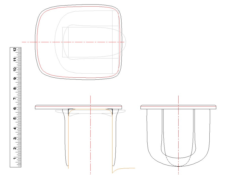
Plan showing open and folded configurations
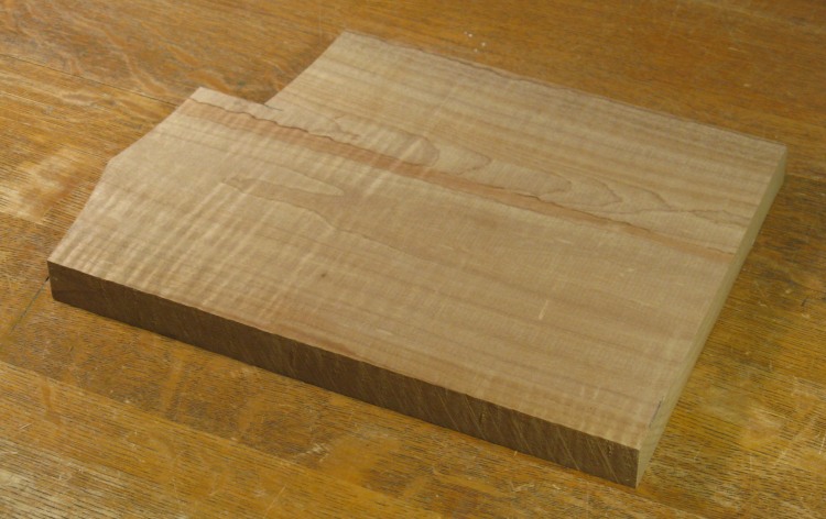
Plank used for the top
The wood used was roasted curly maple, which was chosen to complement the darkish-brown color of the chair. The wood has a nice grain and is reasonably strong as well. The table has three parts; the top, the narrow leg and the open leg.
There were a few pieces of RCM kicking around my shop, but this one was wide enough to make the table top with a single piece. That seemed like a better look than the alternative of a two-plank table, with the added bonus of less construction time.
There were a few pieces of RCM kicking around my shop, but this one was wide enough to make the table top with a single piece. That seemed like a better look than the alternative of a two-plank table, with the added bonus of less construction time.

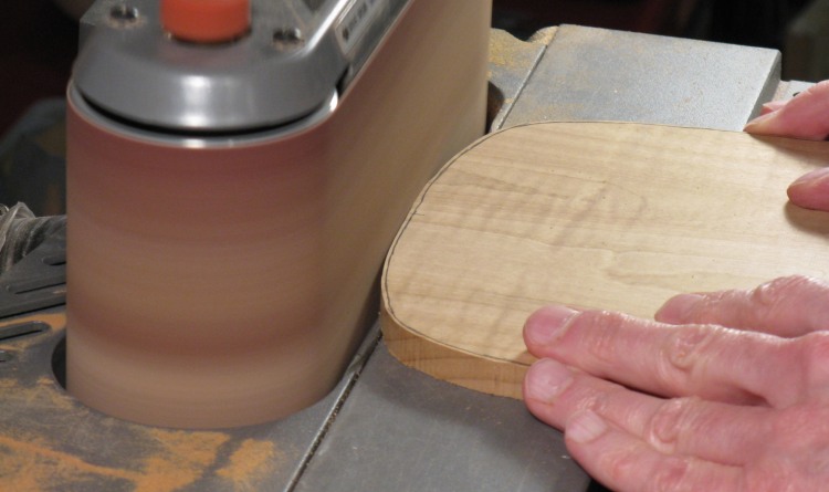
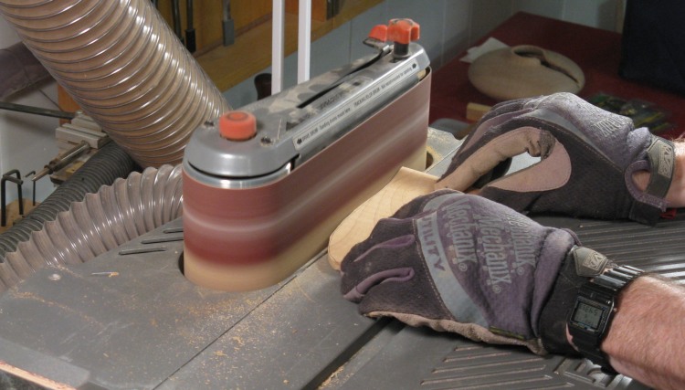
Cutting top to proper thickness
Here it is set up to be cut (or "resawed" if you want to sound all woodworky) to be closer to the final thickness.
Behind, it is supported by a tall MDF fence and there is the black featherboard on the blade side to keep it tight to the fence.
Behind, it is supported by a tall MDF fence and there is the black featherboard on the blade side to keep it tight to the fence.
Shaping the top
And we'll just skip past the thickness planing, outline marking and cutting out the shape to arrive here at using the horizontal belt sander to shape it close to the line.
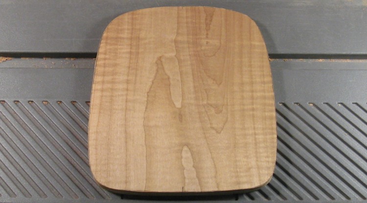
The rough shaping of the top done
And here's the tabletop after shaping on the sander. That was followed up with some hand-sanding to smooth the edges a bit more.
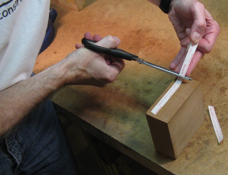
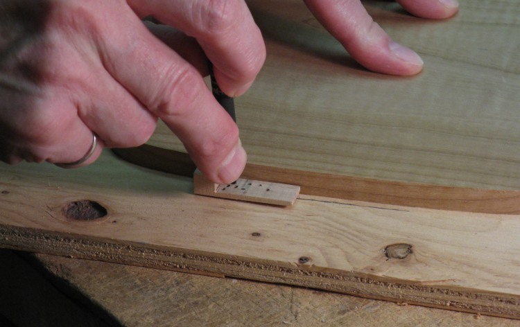
Taping up a handle for a leg
Next up was the legs. The plan was for the legs to be thickish at the upper end to sit squarely against the bottom side of the tabletop, and thinner towards the lower end for that svelte clip-on table look that's all the rage.
The bandsaw was to be used to cut the top-to-bottom contour, so I needed a good way to control the piece when sawing it. For that I made "handles" out of thick blocks of wood. Here a block is having window-plastic sealing tape applied, which will hold it to the leg.
The bandsaw was to be used to cut the top-to-bottom contour, so I needed a good way to control the piece when sawing it. For that I made "handles" out of thick blocks of wood. Here a block is having window-plastic sealing tape applied, which will hold it to the leg.
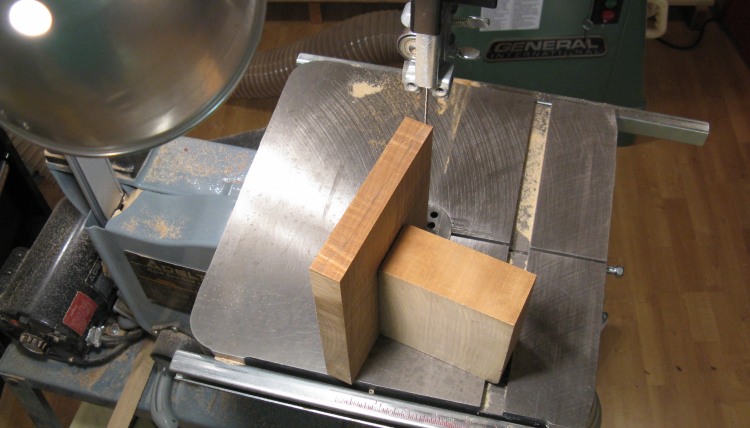
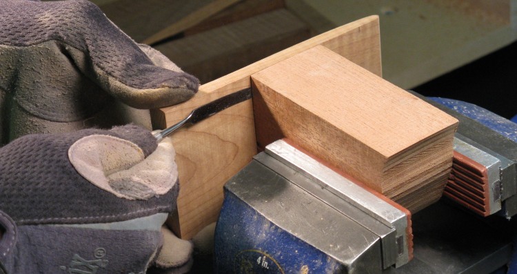
Ready to cut the wider leg to the proper contour
Here the wide or open leg is ready to be cut. The top edge has a (barely-visible) line that it will be cut to.
The handle is square so that it holds the plank perfectly vertical and I just held the assembly by the handle and angled the plank through the saw to cut near the line.
The handle is square so that it holds the plank perfectly vertical and I just held the assembly by the handle and angled the plank through the saw to cut near the line.
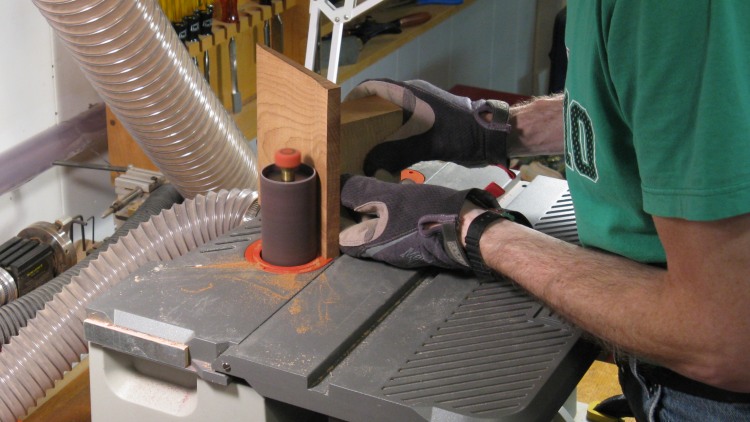
Rough sanding of the wider leg
After cutting, the spindle sander was used to smooth out the curves, with the piece being flipped over to sand both halves.
Yes, that's a Rider shirt. 0 and 9 on the season when this shot was taken. I'm hoping I'll be able to look back on this year and laugh. Eventually...
Yes, that's a Rider shirt. 0 and 9 on the season when this shot was taken. I'm hoping I'll be able to look back on this year and laugh. Eventually...
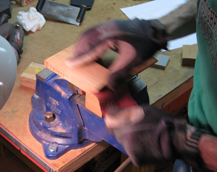
Action shot! Hand sanding leg
A bit of hand-sanding with some appropriate curved wood forms followed. I figured it would be easier to sand now when it was flat and strong rather than after it was cut.
Prying off the handle from the smaller leg
This photo shows the handle being pried off the narrow leg. I used a couple thin spatulas (spatuli?) to ease the pieces apart until the tape finally gave way.
Shaping the outline of the smaller leg
The narrow leg was shaped on the sander after handle removal. Both legs were sanded a bit more to provide some contour at the ends and along the edges, then finish sanded.
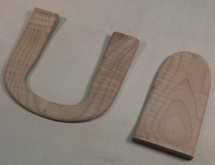
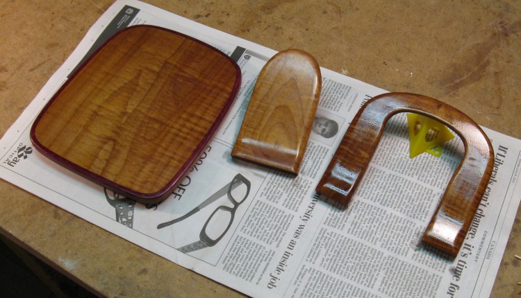
Both legs with shaping and sanding complete
Here the two legs have the shaping and sanding completed.
Table top, again
So at this point I looked at the table top again (yah, same picture as before) and said "that's pretty plain". I figured it needed some edge treatment or something. After a bit of consideration, I decided to add a contrasting piece along the outside edge.
The edge trim was essentially curved inlay work, which I hadn't done much of in the past. There are a few techniques but the standard one I chose used a router. To make sure I was taking the right approach, I gave my older brother a call since he is something of an expert on wood inlays having done many detailed pieces, and it sounded like I was on the right track.
The edge trim was essentially curved inlay work, which I hadn't done much of in the past. There are a few techniques but the standard one I chose used a router. To make sure I was taking the right approach, I gave my older brother a call since he is something of an expert on wood inlays having done many detailed pieces, and it sounded like I was on the right track.
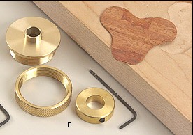
From Lee Valley Tools catalog
There is a small metal fixture for the router that aids the making of inlays. It is usually made to fit on a router, but it didn't fit my particular model. It also can be used in specific router tables, but again, not mine. Since my router table was obsolete I couldn't even buy parts for it to modify for this piece so the upshot of all that is that I first needed to make a fixture to hold the fixture.
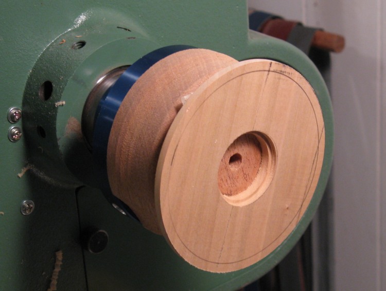
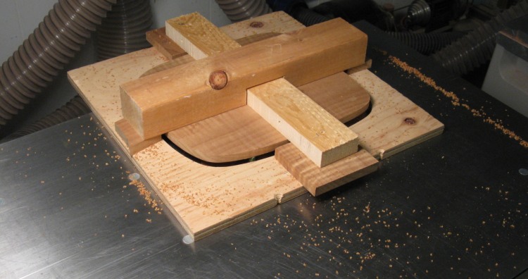
Making a router table insert on the lathe
My router table has circular insets that have a couple lips. The first keeps it from falling through the table and a second one is off-center a bit so that when the insert is rotated, it binds and friction holds the insert in place.
I needed to make one of those inserts to hold the fixture, so of course I used wood, turning it on the lathe. This photo shows the top side of the insert, still on the lathe. The center hole for the inlay fixture has been made and the piece is ready to flip over and have the bottom side done.
I needed to make one of those inserts to hold the fixture, so of course I used wood, turning it on the lathe. This photo shows the top side of the insert, still on the lathe. The center hole for the inlay fixture has been made and the piece is ready to flip over and have the bottom side done.
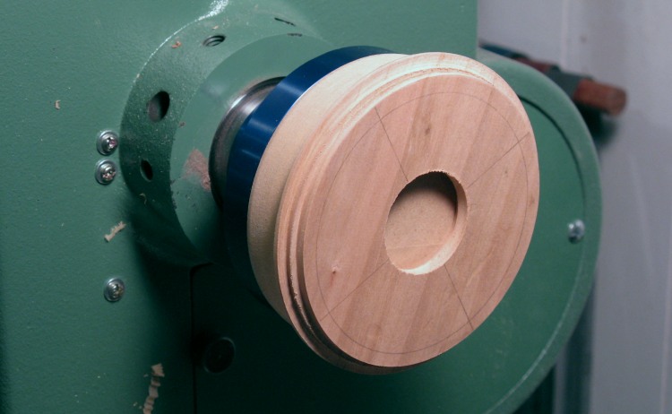
Cutting the bottom side
Here the piece has been flipped over and the center moved a bit so I could turn the the offset lip. The center needed to be moved only 0.015", which frankly is better accuracy than I would expect to position anything by hand. It turned out to be offset about 0.025" instead, but that seemed to work fine.
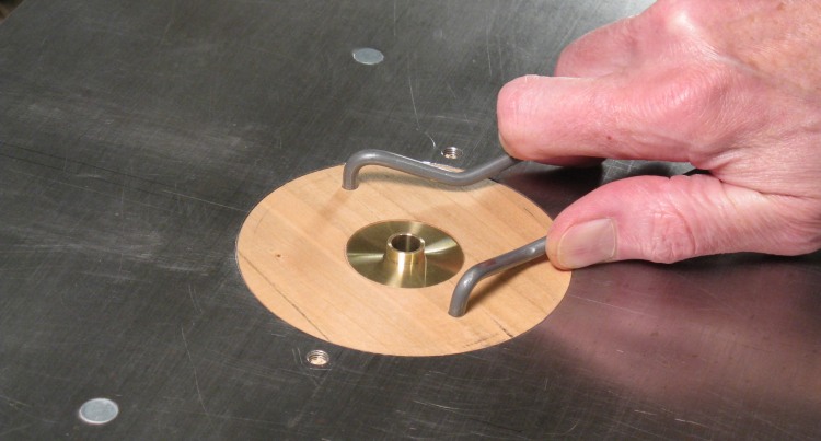
Insert being put in place with inlay guide mounted
This shows the wood insert being installed into the router table top with the wire tool used to rotate it into place. The brass inlay guide has been installed as well.
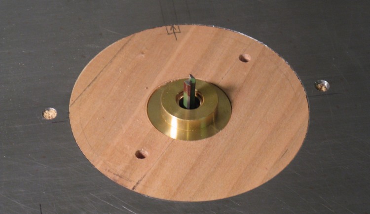
Inlay guide with spacing ring installed (& router bit)
This is another shot of the guide, but with the spacer ring installed. It also has the 1/4" router bit in place.

Inlay scheme
This cartoony diagram shows the general principle;
1. A nice grey template in the desired shape is made.
2. With the gold inlay guide against the template, the inside brown wood is cut using the inside of the 1/4" router bit and the finished contour is a distance D from the template.
3. Then the wider gold spacer is added which moves the bit exactly 1/4" further away from the template. The outside red wood is added and the router cuts using the outside of the bit, but also exactly a distance D from the template so the edges on the two pieces are exactly the same.
Marking a routing template
So step 1 was to make the template. The tabletop was used as a pattern to mark out the shape and this shot shows a little wooden guide being used to draw a pencil line at a consistent distance from the tabletop.
Routing template (first try anyway)
I used 3/8" plywood for the template. Here it has been cut out, and the edges sanded smooth to act as a guide.
I was a bit too enthusiastic in sanding the template edges with the result that the shape ended up being a tiny bit different than the table top. So I made another one with less vigouous smoothing and it worked out better.
I was a bit too enthusiastic in sanding the template edges with the result that the shape ended up being a tiny bit different than the table top. So I made another one with less vigouous smoothing and it worked out better.
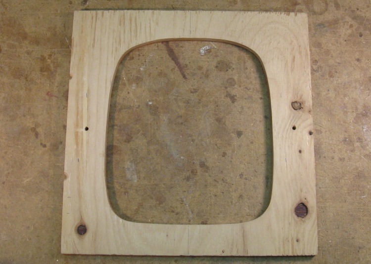
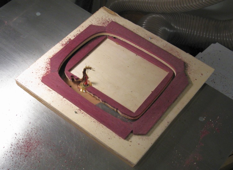
Routing the edge of the top
The tabletop needed to have a step routed in the edge all the way around. In this shot, the top has been mounted face-down to the template with some scrap wood holders and spacers so it can be routed from the bottom.

Edge of top
Flipped over compared to the last photo, this close-up shows the cut-out edge of the tabletop, still mounted to the template.
Gluing up the trim
The next step was to make the edge trim. I had no wood wide enough to do it with a single piece, so I just made an outline with four smaller pieces glued at the edges.
This is actually the second try shown here. Round one was a resounding failure as the trim was insufficiently constrained and got a bit...well...shattery. In this revised method the trim is actually glued directly to a piece of thin plywood so it was goin' nowhere.
This is actually the second try shown here. Round one was a resounding failure as the trim was insufficiently constrained and got a bit...well...shattery. In this revised method the trim is actually glued directly to a piece of thin plywood so it was goin' nowhere.
Trim routed out using template
This shows the trim after being mounted to the template and routed, right through the thin piece of plywood.
This orientation was necessary so the flat top surface of the trim could be flipped and sit against the matching notch in the tabletop.
This orientation was necessary so the flat top surface of the trim could be flipped and sit against the matching notch in the tabletop.
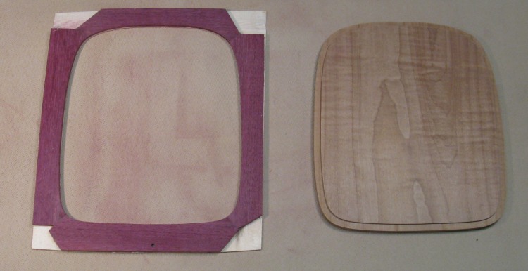
Trim (after trimming) and top
The original plan was to use the bandsaw to cut the trim off the mounting piece of plywood, but that didn't pan out. The blade started to wander and cut into the trim, so I abandoned that about 0.01" prior to disaster and just used the belt sander to remove most of the extra plywood. I kept a bit of the plywood in place to provide some additional strength for handling and gluing.
The trim is shown here with the sanded-down plywood as well as the top with the notch ready to accept the trim.
The trim is shown here with the sanded-down plywood as well as the top with the notch ready to accept the trim.
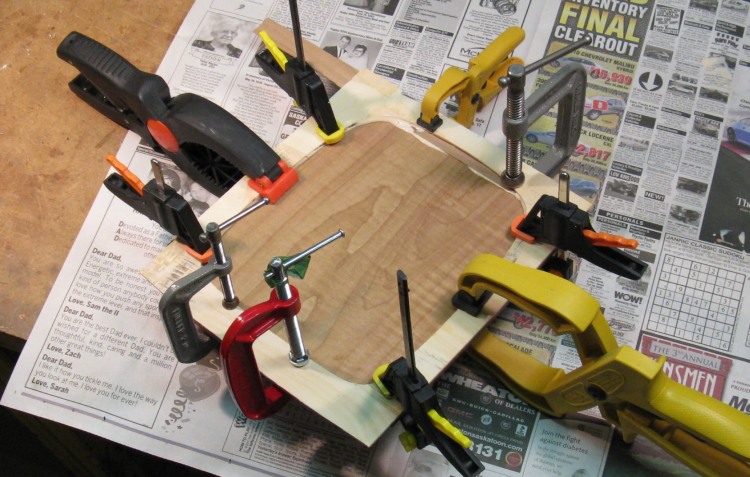
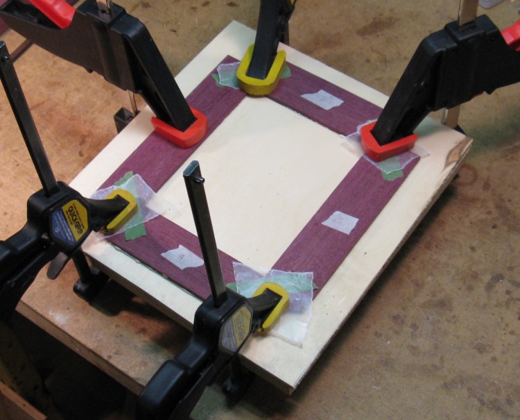
Gluing trim to top
So then the trim piece was flipped over and glued to the tabletop with normal wood glue, using lotsa mismatched clamps to make sure there were no gaps between the top and the trim.
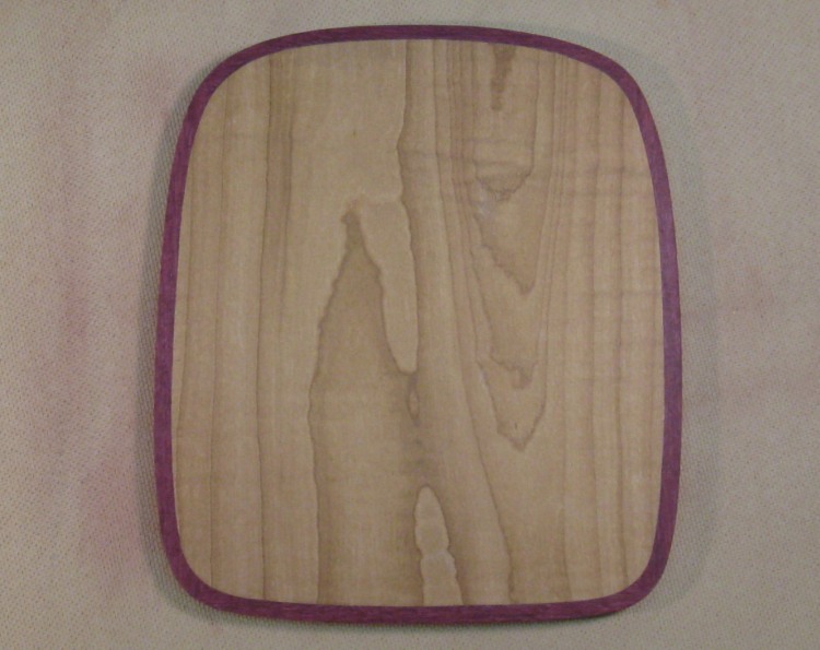
Top cleaned up
The excess trim and backing were removed by sanding. Here's the tabletop with the trim in place.
OK, the red trim actually looks a bit odd, and something closer to black might have been a better choice. Ah well, maybe next chair-arm table...
OK, the red trim actually looks a bit odd, and something closer to black might have been a better choice. Ah well, maybe next chair-arm table...
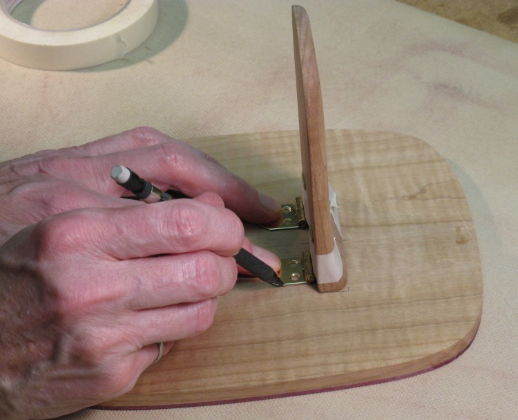
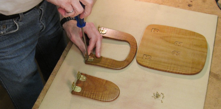
Marking hinge positions
With all the pieces completed, the next step was to mark the hinge position. I thought the hinges would look more finished if they were inset into the wood, so here they have been taped to the narrow leg and the outlines are being marked on the bottom side of the tabletop.
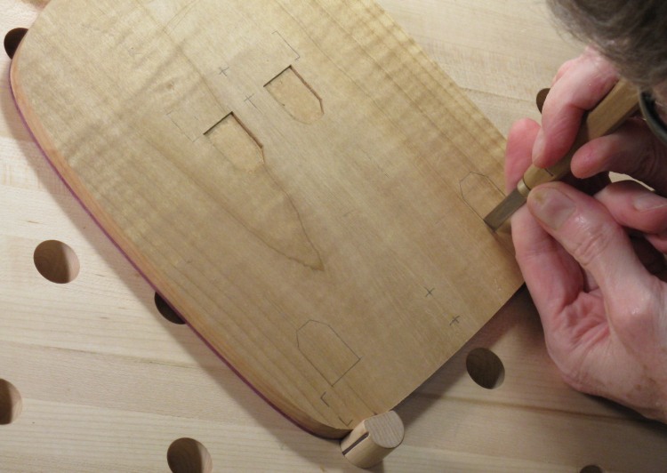
Trimming edges of hinge cutouts
I used a Dremel tool with a small cutter and a router attachment to mill out the bottoms of the hinge positions to a consistent depth, and then trimmed the edges by hand as shown here. The top two positions have been completed and I'm just starting the first on the bottom.
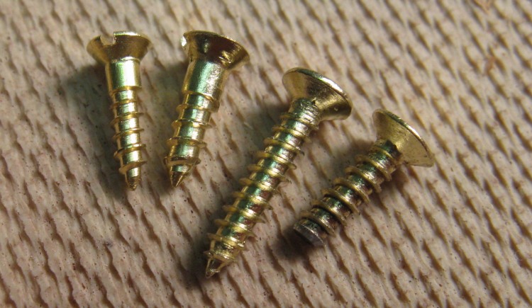
Hinge screw comparison
The screws that came with the hinges were too long for this application. They were close to 1/2" and I needed something closer to 1/3". I bought a couple shorter brass screws but they didn't have very good-looking threads compared to the originals.
The two on the left are #2 and #3 brass screws and the long one is the original #2, presumably brass plated steel. I decided the best approach was to grind the original screws down to the length that was needed like was done with the rightmost screw.
The two on the left are #2 and #3 brass screws and the long one is the original #2, presumably brass plated steel. I decided the best approach was to grind the original screws down to the length that was needed like was done with the rightmost screw.
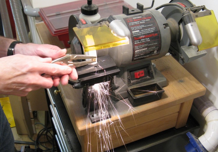
Gratuitous sparky grinding shot
I made a little jig (a cube of wood with a hole in it) into which the screw could be driven. Then the jig was placed in the jaw of a vise-grip which was hand-held to grind down the screw (about a 5 to 10 second process).
The screw end was smoothed using the belt sander so the threads started properly. This is a somewhat mundane procedure, but it was a good excuse to take a nice sparks-flying photo.
The screw end was smoothed using the belt sander so the threads started properly. This is a somewhat mundane procedure, but it was a good excuse to take a nice sparks-flying photo.
Test fit of pieces
With all the hinge cutouts done and the screw holes carefully drilled, this shows a test assembly to make sure everything fits.
Wet varnish
I then applied finish to the three pieces, which consisted of three coats of polyurethane varnish with this photo showing the still-wet first coat.
Final assembly
And when dry, the final assembly was done.
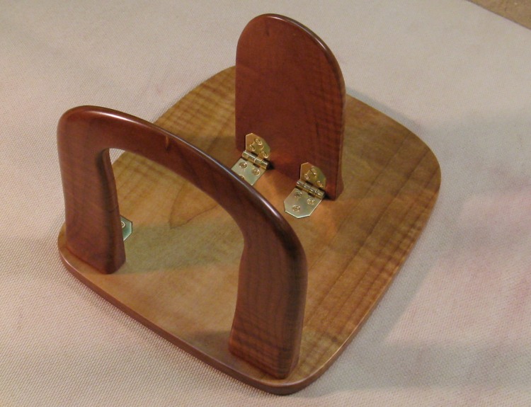
Holder in open position
Here the (upside-down) table is in the deployed position.
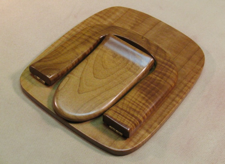
...and folded position
And here in the folded position for storage.
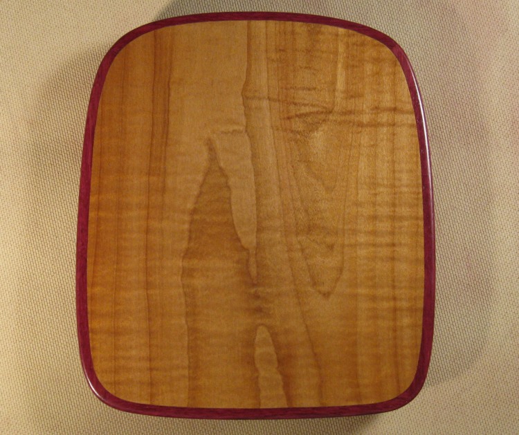
Top side
View of the completed top side.


