Our antique-style side tables don't match except in general size and class; antique-ish, shaped plank top; so those general constraints along with the one-inch-thick roasted maple availability called for a design that worked with no more than about an inch of thickness. There didn't seem to be much out there in existing tables to use as a starting point, so I ended up creating something from scratch.
I took a few photos of the construction, but they are somewhat limited in scope. Those that I have are below.
The plans below show the final design. I decided to make this one a magazine-holding table, more for the extra strength of the magazine rack than any overriding need for more periodical storage. I also added a stretcher or web under the top, since it seemed like it needed a bit more detail in there.
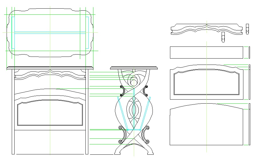
Final plans
Wood
As described on the main page, roasted curly maple was used for all parts of the table. I think I started with about a dozen board-feet, and there wasn't a whole lot left over.
Top
The top was pretty straightforward. I chose some pieces of wood with interesting grain, and made planks just under three inches wide to laminate. There was quite a bit of variation in the grain patterns, so instead of trying to match grains, I went for the symmetrical look. The shot below shows the top after lamination but before shaping. It looks pretty thin in this photo, but the top is just over 3/4" thick.
Glued-up blank for the top
Ends
The ends started out much as the top did with laminated planks. But instead of using relatively narrow planks, I chose wider ones so as not to have a grain change in the middle of the carved design. The shot below shows the two ends after lamination, and you can see that the main plank covers all but the outside 1" or so.
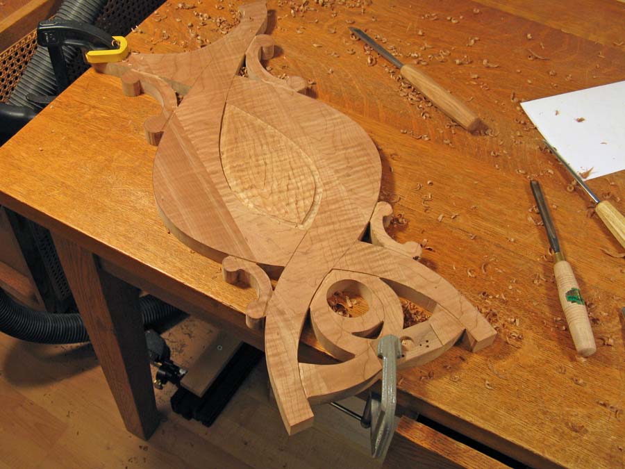
The pattern for the main contour can be seen in the photo below. The main outside shape has been roughed out with a bandsaw, and I've drilled holes for insertion of a saber saw blade to cut out the required through-holes.
The pattern for the main contour can be seen in the photo below. The main outside shape has been roughed out with a bandsaw, and I've drilled holes for insertion of a saber saw blade to cut out the required through-holes.
The two ends cut to shape and marked with the design. The holes are for sabre-sawing
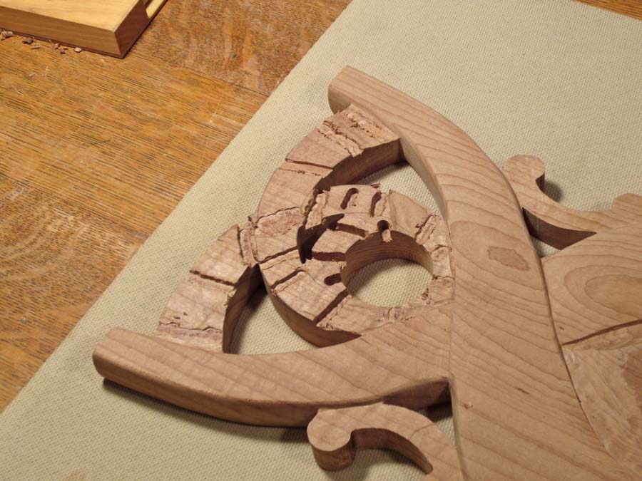
The next shot shows one side with the through-holes cut out and some carving done to distinguish the middle section. At this point, I hadn't completely decided on the design for the center, so I was mostly making sure that the curved outside sections were defined. At this point, the edges have also been smoothed through sanding and filing.
One end with the center section carved
I also hadn't originally had a well-defined plan for what the contour of the sides would look like (just that flat wasn't going to cut it), but it became more obvious that they should be gently rounded, and appear to go over/under the intersecting curves.
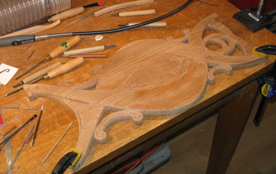
Thus began an epic of sanding. I did some basic tool-based shaping of the overlapping curved sections, but they needed sanding to ensure smooth convex curves. Much of the sanding was done using a little power detail sander (Dremel Multimax), which can be pretty effective at material removal even into corners. Unfortunately, one rather long sanding session resulted in a partially numb arm for a few hours due to the vibration, so I limited future sessions to avoid a repeat of that particular malady. The edges were also contoured to conform to the general rounded look. The shot below shows the main body of one of the ends with the surface contours mostly complete. The bottom web has also been carved, and the top section is being prepped for carving.
Thus began an epic of sanding. I did some basic tool-based shaping of the overlapping curved sections, but they needed sanding to ensure smooth convex curves. Much of the sanding was done using a little power detail sander (Dremel Multimax), which can be pretty effective at material removal even into corners. Unfortunately, one rather long sanding session resulted in a partially numb arm for a few hours due to the vibration, so I limited future sessions to avoid a repeat of that particular malady. The edges were also contoured to conform to the general rounded look. The shot below shows the main body of one of the ends with the surface contours mostly complete. The bottom web has also been carved, and the top section is being prepped for carving.
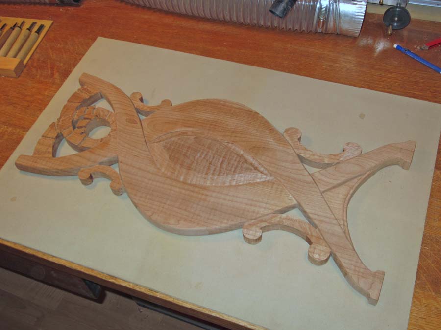
Basic shaping and contour work done
The sides were roughed with the flat side of a half-round file. That file was coarse enough to cut fairly aggressively, and fit better into the triangular holes than a rectangular-sectioned file would. The tapered shape also helped it get closer into the corners. One tool that I found quite handy was a curved and tapered Japanese finger file, which is an odd little stainless steel file with "safe" edges., that was very effective for working into corners. I also used finer files and sandpaper strips for clean-up.
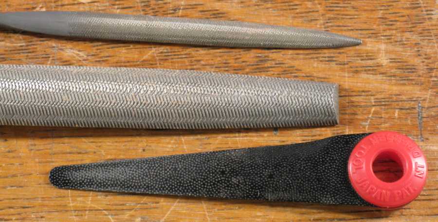
Files used for contouring edges
To complete the top section, the various surfaces had to be contoured to specific depths. I used a dremel bit in the drill press to machine some depth-guide holes or slots as can be seen below. The procedure was then to carve by hand down to the depths of the slots to get the rough contours. And then of course more sanding to smooth it all out.
Top section with depth-guide cuts made, ready for carving
The "scrolls" first had their sides rounded in a similar manner to the main body, although they didn't get the radiused corners. Then the "showy" side of the end had the scrolly parts carved in. Below is a little montage of the scroll carving. That was just carved by hand as shown, and then, yes, sanded.
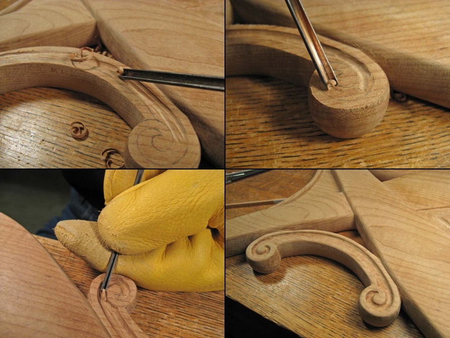
Scroll carving details
I didn't put any carving detail on the flip side of the ends. All the corners are rounded to match the main side, but the none of the surface detail is there. The scrolls are just delineated with narrow slots. That "B side", however, has routed slots to accept the magazine rack sides and bottom, although there is no photographic evidence to back up this particular assertion. The shot below is one of the ends with the carving complete except for the center detail.
All carving and shaping done except for center detail
An additional detail not shown is the splinter-prevention foot pads. With the grain in the ends oriented vertically, there isn't a great deal of strength in the feet, and I have seen a table with this grain orientation where a piece of the foot is broken off, presumably due to uneven forces on the feet.
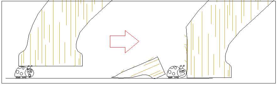
Vertical-grain foot weakness illustration
To prevent this, I added a thin (1/8") lamination on the bottom of each foot that provided a less-delicate resting surface.
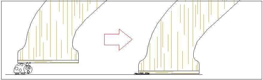
More-robust foot design
Sides
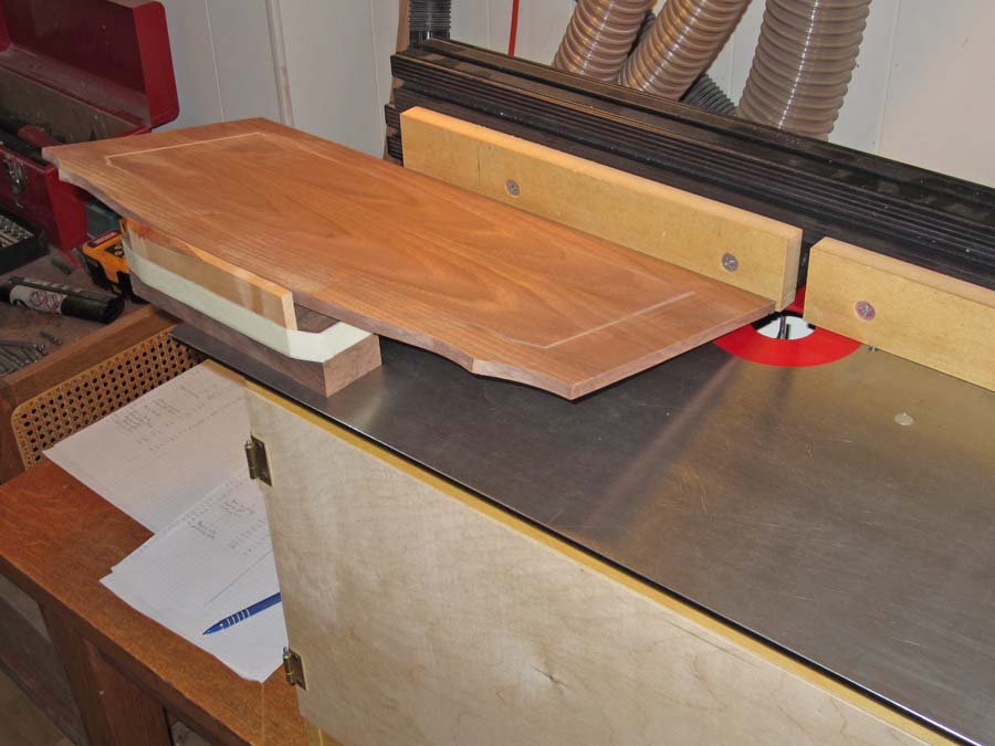
The side walls of the magazine rack were panels about 1/3" thick. A taller center panel is flat on both sides, but the two outside panels were to have a flute (a round groove) echoing the edge profile. I made the grooves using the router in an effort to make smooth curves. The wooden jig shown below is sometimes called birds-beak guide, and it keeps the edge of the wood a measured distance from the router bit. I added a wire loop, which is positioned just over the router bit to provide an indication of exactly where a cut is being made on the other side, so that intersecting routed segments of the groove can be stopped at the correct spots. To make the grooves, I taped a sheet of paper to the panel (just to have better contrast) and marked the corner areas where three grooves intersect. I then routed each segment using the wire as a guide on the pattern to judge when to end each segment.
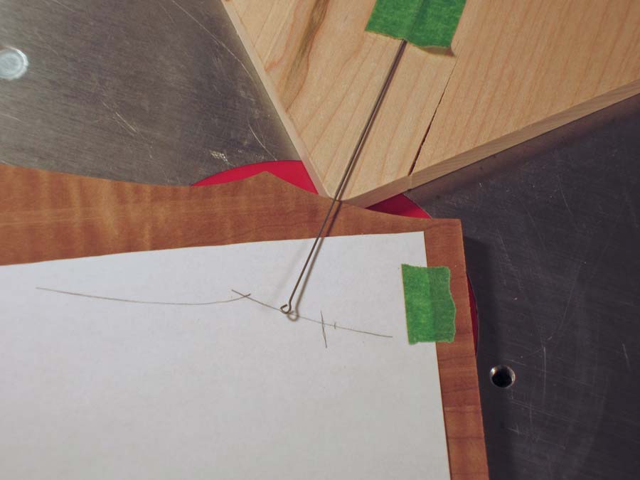
Flute-routing guide on router table
The shot below shows one of the outside panels with the full groove completed.
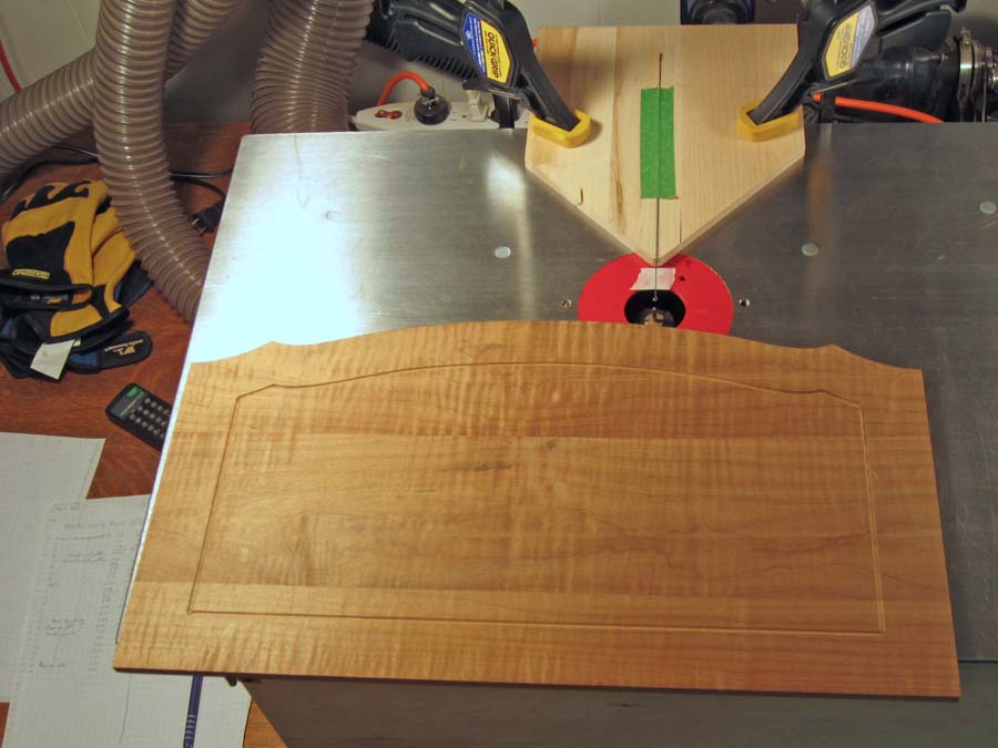
Magazine rack wall with flute pattern completed
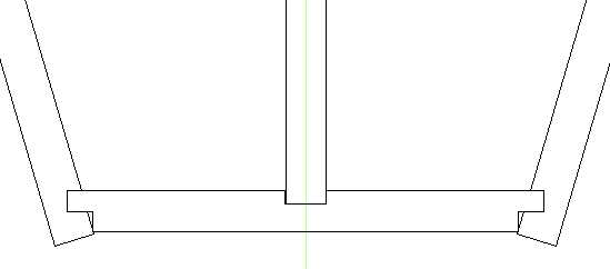
Magazine rack wall assembly detail
The two sides and the center divider assemble to a flat bottom for the magazine rack. In the case of the center divider, it fits into a slot in the bottom, while the sides each have a slot for the bottom to mortise into.
The shot below shows the setup for cutting the angled slot in the sides. The sharp-eyed may notice the rather more walnutty look of the wood in the panel shown, and this is due to it being for another table that I was making at the same time.
In fact, I was getting tired of all the sanding required for this table, and thought I'd start my next project before it was done, so that I'd have something less sanding-intensive to work on when I felt I needed it. The next project was another side table, in Walnut, basically to hold up a spare table top I had left over from the previous table I made. This actually worked out well since I could do some common processes (like route the magazine rack sides) for both tables with the same setup.
Routing the floor-mating slot in a magazine rack wall (for a different table actually)
Below is a closeup of the 1/8" router bit and the slot it has cut.
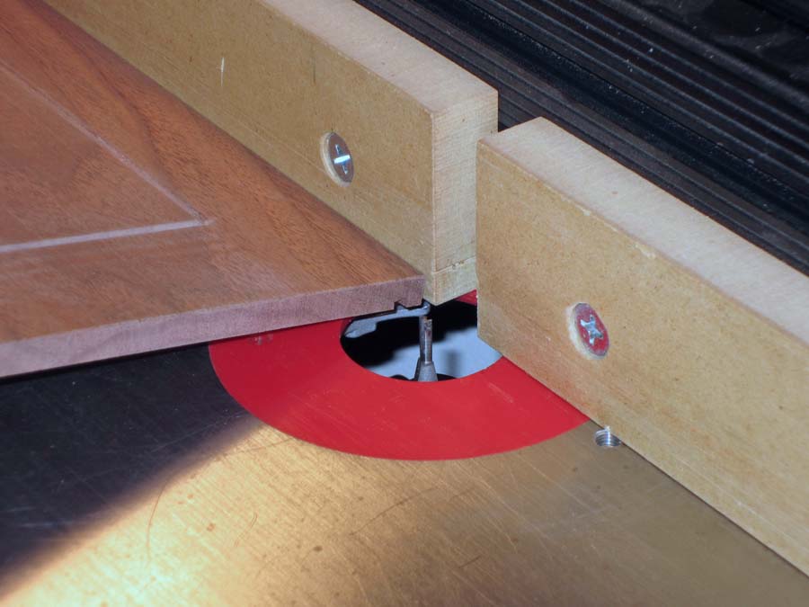
Close-up of routing angled slot
Web
The web fits under the top and spans between the two ends. It probably isn't necessary for strength since the magazine rack walls provide lots of stiffness to the table, but it fills an otherwise empty span between the ends. This piece was shaped with my normal method of bandsaw and spindle sander, and then the outside edges were routed to a semi-circular profile. The inner profiles were carved by hand as shown. The right side has been completed, and the left side is partially done in the shot below.
This piece was held in an old Workmate with the help of some "bench dog" style clamps that fit into the holes in the top. This worked out reasonably well except the Workmate isn't very rigid - especially side-to-side - and tends to wobble when lateral pressure is applied, as it was for carving this piece. I braced it against the nearby table and usually held it with one foot for more stability when carving.
The holes on the left-hand side were drilled with a flat-bottomed bit to act as depth guides to ensure I had the desired depths along the groove.
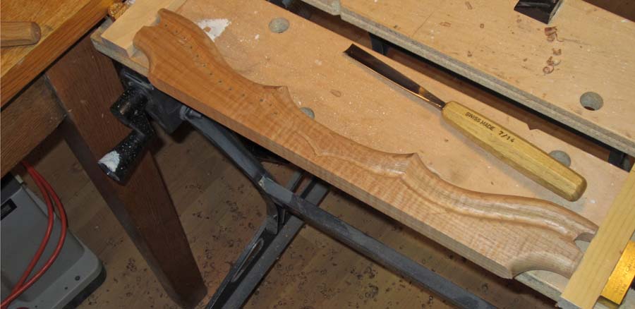
Carving half-done on web pieces
A closer shot of the partially-carved side is shown below.
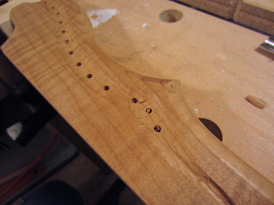
Depth-guide holes
Assembly
Some furniture has connected pieces with a mixture of grain orientations - maybe a table with an attached skirt that has it's grain running at right angles to the top. This can be a bit of an issue since wood expands much more across the grain than along it, so glue joints can be stressed and perhaps fail prematurely due to seasonal changes in the wood dimensions (due to differing winter/summer humidity, which affects even wood with protective finishes). Most of my other tables have had this construction, so the tops were attached in a manner that permits some size change without stressing joints. However, that isn't an issue for this particular table since the grain of the ends and top are in the same orientation and they should expand and contract similarly. That meant that the top could be directly connected to the ends, simplifying construction a bit.
The assembly proceeded in two stages:
- I first assembled the the ends with the magazine rack; The four pieces forming the magazine rack fit together and into matching slots on the ends and were glued at all the joints.
- Then the top was added, using short pegs between the tops of the ends and the bottom side of the top. Pegs were also used to connect the web to each end. All joints were glued.
Finishing
Finally, the assembled table needed an appropriate finish applied before it was complete. I used three coats of Miniwax Satin Wipe-on Polyurethane varnish. Steel wool of grade #0000 was used between the coats to roughen up the previous coat for better adhesion, with vacuuming the residue off and using a tack cloth to remove any remaining steel wool particles. This was all a bit time-consuming due to all the crevices that needed to be done, so it took an hour or two for the sanding and dusting, and about an hour more to apply each coat of finish.
The completed table is shown below.
The completed table is shown below.
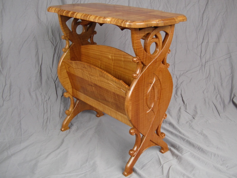
Completed


