This is the third in a series of end tables for our living room. I hadn't originally planned to make three, but the top for the
first one I made didn't look quite right when the table was test-fit together, so I made a new, larger top for it. Then the next table was made from a different type of wood, so it was obviously not a candidate for the top. Consequently, there was a spare table top cluttering up the shop. Of course, the top is probably the easiest part of the table to make - representing maybe 5% of the effort for a complete
table. However, despite the clear mathematical disadvantage, I decided to spend the other 95% of the time and make the rest.
That being said, this table is somewhat simpler than the other two, having fairly straightforward turned legs and basic ends. However, I succumbed to the temptation to add some carving detail (to at least one end), which upped the effort a bit. Even so, it took less than half the time of either of the other tables.
I actually started this table before completing the last one I was working on, which is unusual for me. There's not much advantage to having more than one project going at the same time - it tends to use up shop space and not save any effort. However, the last table was sufficiently sanding-intensive that I was looking for some relief. Making this one gave me something to do when I tired of sanding and shaping. It did have the advantage that I could do some routing on the magazine racks for both tables with one setup, which must have saved 15 or 20 minutes. Wohoo!
I didn't spend much time documenting the construction of this table, since the basics are pretty similar to others I've done before. Plus, I forgot. So what I have is mostly concentrated on the assembly of the table, a subject on which I didn't have much detail for the others.
As usual, the plans below show the design. This one is a magazine-holding table, with exactly the same magazine-rack design as the previous table. It also incorporates a pair of slightly ornate corner braces for a bit more rigidity and to add some visual interest in the large open area above the magazine rack. As shown the two ends sport different designs.
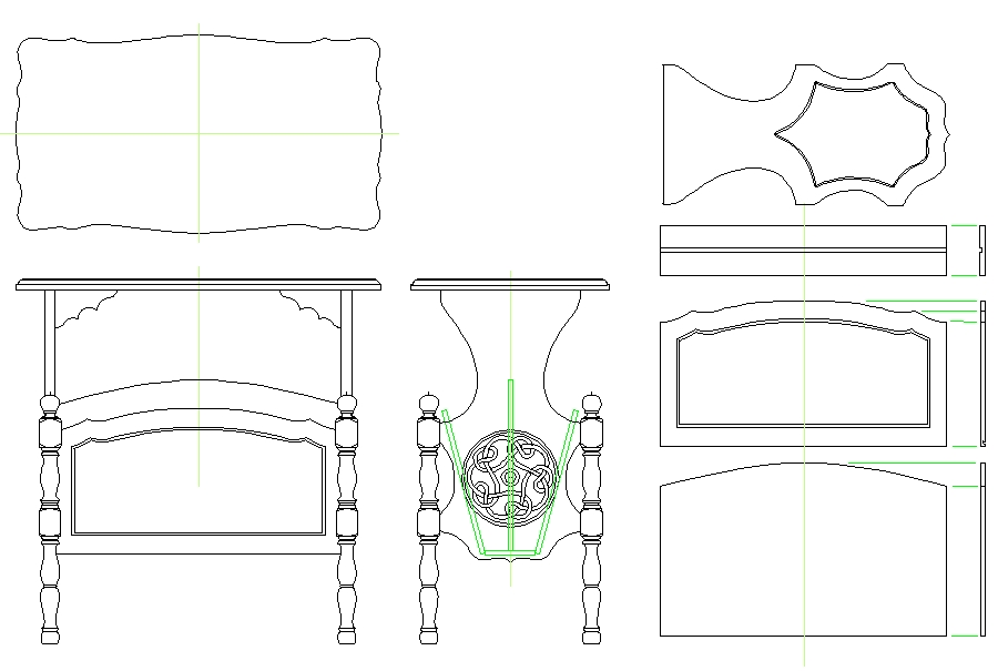
Plans
Wood
This table is Walnut, made to match the existing top. The top was made the previous year, and I used wood with some fairly nice grain that I had acquired for it back then. I also bought some 2" stock for the legs this year, and then for the remainder, I was able to bum some walnut planks off a generous brother, who had bought a goodly pile on speculation some time ago. As a result, the light-coloured legs don't quite match the more deeply-coloured ends, with the top being somewhere in between. But it's all Walnut. I'm pretty sure.
Top
As mentioned, I was using an existing top. There is excruciating detail on it's construction here. The shot below shows the top sitting on the table that I figured it didn't fit.
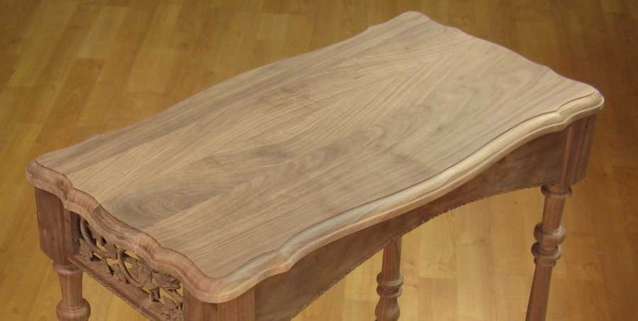
Spare Table top shown on original table
Legs
The legs are 100% undocumented, picture wise. But I won't bore you trying to produce a 1000-word equivalent description. Instead I offer this 38-word "thumbnail" as it were; The design of the legs was an amalgam of a couple of different turned-leg tables we have. The legs were fairly simple since they were only 3/4-length, and it took about 8 hours total to complete them.
Ends
The ends of the table were actually narrow enough that I could make them from a single plank, rather than having to laminate - a nice change since it eliminates the edge jointing, gluing up and planing associated with laminated pieces. And since they were a fairly straightforward design, they were dead simple to make. I did the normal; trace the pattern / cut out with bandsaw / sand to the pattern with spindle sander. That got the basic ends in shape.
The next step was to add the routed slots for the magazine rack walls to mortise into. These were just straight slots, but they needed to be at a specific angle and length on the back of the oddly-shaped ends. Fortunately, I had come up with a workable technique on the last table, which I reused. The first step was to mark the slots on the back of the ends. Then:
1. Set the router fence a specific distance (say 6") from the router bit;
2. Make a thin rectangular sheet of wood that was a bit narrower than the fence-to-bit distance;
3. Stick the sheet to the back of the end next to where the routed line is to go. So for a 5.75" sheet, I would put it 0.25" from where I wanted the edge of the slot. Thin double-sided tape was used to stick it on.
4. Mark on the top of the sheet where the ends of the slots should be.
5. With the sheet against the fence, route the slot between the end marks.
This worked pretty well, and while it took a bit of time to set up for each slot, the actual routing was pretty simple. It usually needed a second sheet of wood on the work piece to make sure it sat flat on the router table. The shot below shows the back of one of the ends with the sheets on it. I actually used a slotted sheet for this one so I would have more area to stick the sheet to the end.
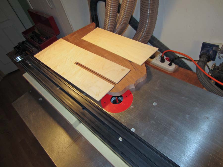
Table End with guide sheets stuck on for routing slots
The shot below with the rather odd perspective shows the end positioned on the router table, with the guide sheet against the black router table fence. As can be seen, the slot will be cut parallel to the fence as everything slides along, but at an angle to the end, corresponding to the angle at which it is positioned relative to the fence.
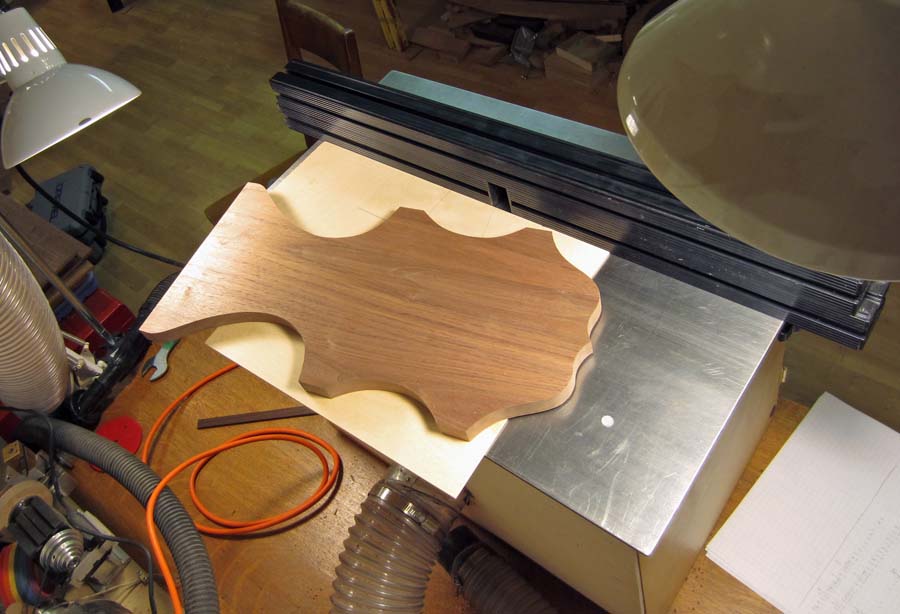
Table End on router having slots routed in the bottom side
Below is a close-up of the guide sheet with one of the slots routed in it. You can see some pencil guide lines to mark the edge and end of the slot. The line that is marking the end would extend to the edge of the guide sheet, and be marked on the top side so that I could see it when routing. I put a corresponding line on the router table marking the edge of the router bit so that when the lines match up, the slot extends to the correct point.

Guide sheet showing slot in table end, and pencil marks to align things
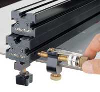
Fence position tweaker
In general, the slot widths that were needed didn't correspond exactly to a standard router bit diameter, so I used a bit with a smaller diameter. After making the initial, too-narrow slot, the extra width needed was calculated, and the position of the fence was tweaked this amount to move the whole assembly the required distance further from the bit. For that I used a neat little thumb-screw-based "micro-adjust system" to accurately move the fence position. Then I did a re-cut, which just widened the slot to the correct dimension.
Now we skip ahead in time about 17 carving-hours to get to the next picture. This shows the "ornate" end with the Celtic knot pattern already pretty much complete. This was mostly carved by hand, with the assistance of the drill press working like a milling machine to cut the base of the pattern to the correct depth. The ring around the pattern still has to be carved. You can sort of see the worm-like squiggles in the base of the carving area. After much consideration and experimentation with textures, I decided that I was unlikely to come up with a much better texture for the base. And I decided I preferred this to just sanded flat, so aside from smoothing a few overly-noticeable areas, I left the base as it was.
Now we skip ahead in time about 17 carving-hours to get to the next picture. This shows the "ornate" end with the Celtic knot pattern already pretty much complete. This was mostly carved by hand, with the assistance of the drill press working like a milling machine to cut the base of the pattern to the correct depth. The ring around the pattern still has to be carved. You can sort of see the worm-like squiggles in the base of the carving area. After much consideration and experimentation with textures, I decided that I was unlikely to come up with a much better texture for the base. And I decided I preferred this to just sanded flat, so aside from smoothing a few overly-noticeable areas, I left the base as it was.
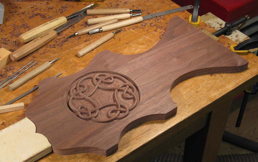
"Ornate" table end mounted for carving with knot design almost complete
Below is a shot of the start of carving the ring around the main pattern. There are a few imperfections visible like where the drill press-mounted cutting bit made a slight notch in the edge of the ring to the left of the chisel blade. This was somewhat less obvious after the ring carving was complete since much of the notch was removed in rounding the ring. The knot pattern is also fairly basically shaped at this point (one flat facet opposite the notch is particularly obvious). This was later rounded more finely using chisels,
but I decided to stick with a minimal-sanding approach and left the pattern with what might be called a cutting-tool finish.
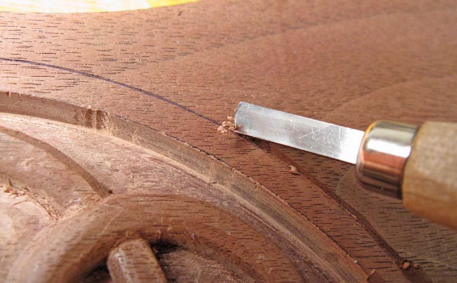
Starting to carve the ring around the knot design with cheapo little carving gouge
Assembly
All the main pieces (except the top) are shown below in the "table kit" shot. The legs still have material on their bottoms that need to be trimmed, and below them are the two buttresses that mount under the top. Beside the legs, the two ends are shown, with the secondary end (the "B" side) having only some simple trim slots or flutes echoing the lower part of the profile.
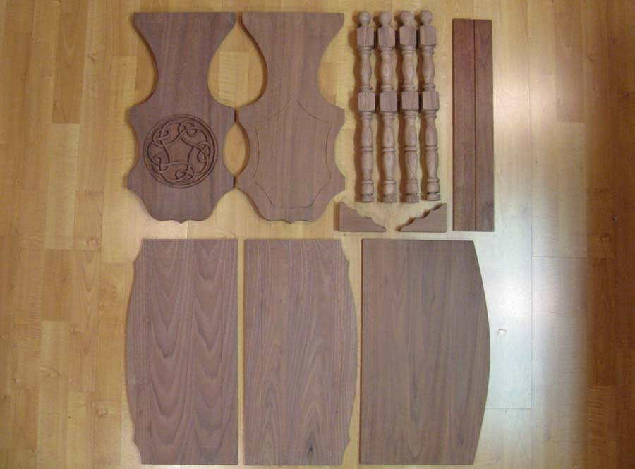
All the main pieces (excepting dowel pins) for the table
The legs were attached to the ends using dowel pins for extra strength. The standard fluted gluing dowel pins are a very tight fit in a nominal-sized hole - in fact they are a few thousandths of an inch oversized, and they need to be tapped in with a hammer. Given this lack of play, when more than one dowel is used, a perfect hole spacing would be required. Even a small mismatch in hole position would be enough to put a great deal of stress on the wood or prevent the pieces from fully assembling. And I can pretty much always rely on imperfection, especially when drilling. For that reason, I drilled nominal-sized holes in the table end, but used one nominal-sized hole, and one oversized hole (by 0.01" or so) in the leg to accommodate imperfection. You can almost see that the left-hand hole in the leg is the tiniest bit bigger than the other three. As it turns out, on one of the 4 legs my drilling imperfection exceeded my imperfection accommodation by a few thousandths of an inch, and the joint wasn't quite perfect. Fortunately, that isn't something that is very visible when the table is fully assembled.
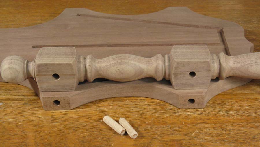
One of the table legs and ends with holes for dowel pins
The legs are being glued to the "B" end in the photo below. This was a pretty simple process since the dowel pins aligned everything and it was just a matter of clamping (and then removing any glue squeeze-out).
The "B" side end having the legs glued in place
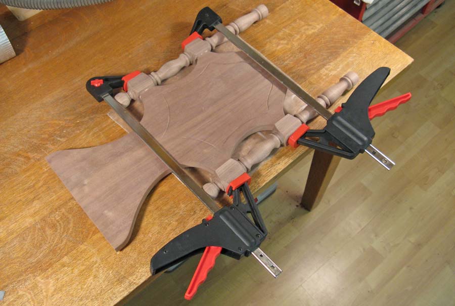
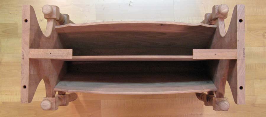
After the legs were attached to the ends, the next step was to assemble the ends with the magazine rack walls. The shot below shows this happening. The walls of the rack slide into the slots cut into the backs of the table ends. However, in order to ensure that the ends were square, I wanted something more reliable than the rack sides to determine the spacing of the ends. For that, I just cut three pieces of scrap wood to equal length to establish the end-to-end spacing. They can be seen just under the top clamp, and also at the bottom sitting on the upside-down table top.
This shows the table assembly sitting on the upside-down table top, but that was only for fitting purposes. I wanted to ensure that the ends were square to the top as they were being glued.
This shows the table assembly sitting on the upside-down table top, but that was only for fitting purposes. I wanted to ensure that the ends were square to the top as they were being glued.
The two ends being glued to the magazine rack pieces
The shot below shows the top spacer board. The masking tape is used to ensure the walls are held flat against the bottom piece as the glue sets.
The spacing bar shown holding the ends apart the correct distance for assembly
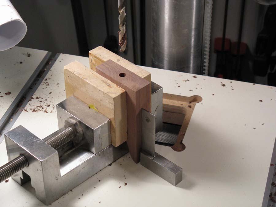
One of the buttresses being drilled for a dowel
The next step was to add what I'm calling the top buttresses. These were dowelled into the ends as shown in the picture below.
Above, one of the buttresses is shown being drilled on the drill press. The little "engineer's square" was there to make sure the piece was mounted in the vise with the correct alignment.
The picture below shows the buttress sitting on top of one of the ends, with the dowel pin already in place in the end. The masking tape was added to provide an guide to make sure the pieces were mounted vertically.
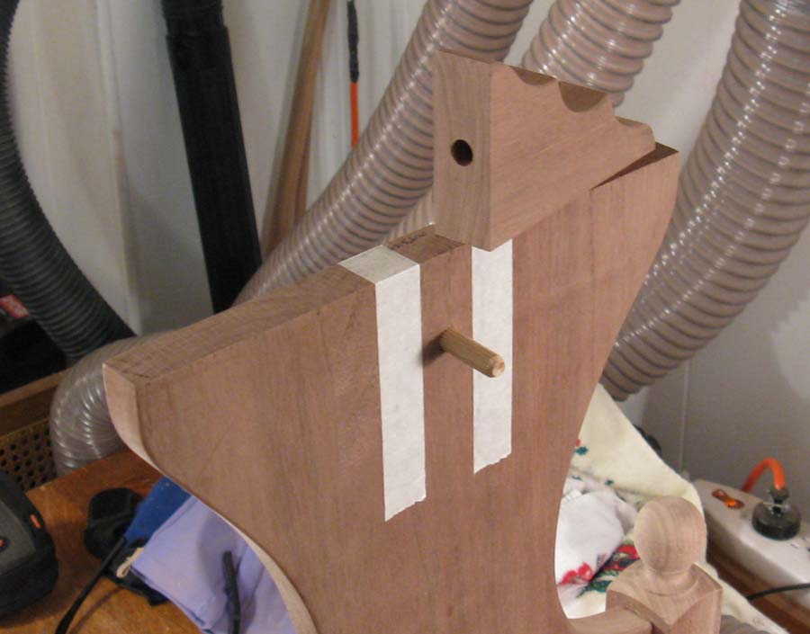
One of the buttresses with matching dowel in the table end (the tape is for alignment)
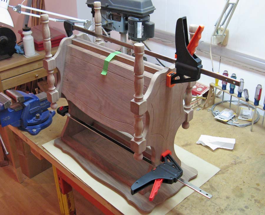
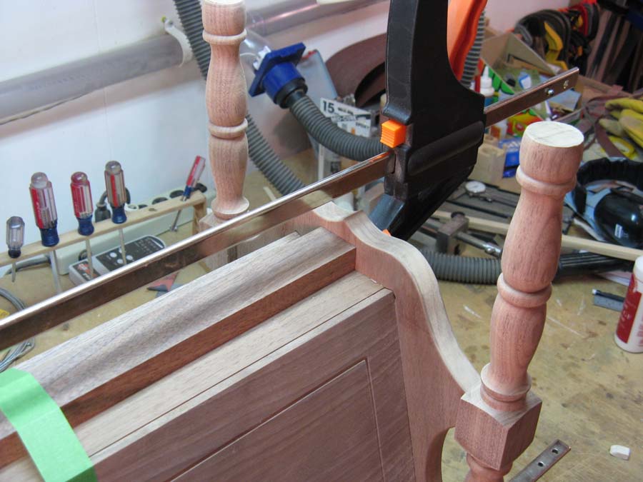
Below is a shot of the buttress at the other end being clamped for gluing. The long black piece is a straightedge, there to help ensure that the buttress was mounted horizontally and even with the top of the end. Clamps hold everything in place.
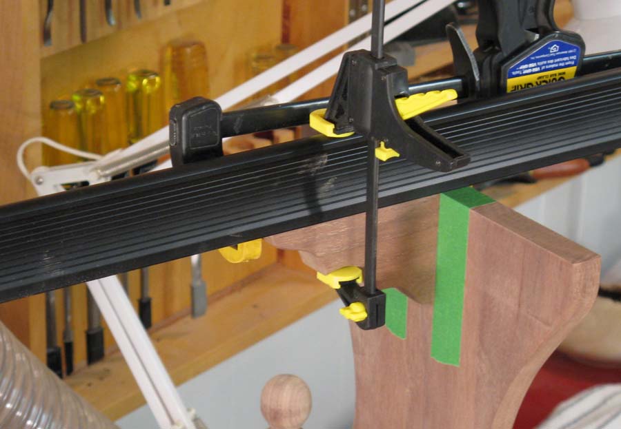
Clamping the buttress to the table end
The next step was to prepare the table to mount the top. The plan was to use dowel pins for the top as well. However, marking hole positions in mating pieces can be a bit troublesome, especially if good accuracy is needed. I decide to use a technique where small marking pins are placed in one piece, which when pressed to the mating piece, will mark the center of the holes.
First, I made the marking pins from some 1 1/4" common nails which were cut short and had the ends rounded a bit;
First, I made the marking pins from some 1 1/4" common nails which were cut short and had the ends rounded a bit;
Nail-based alignment pins used to mark holes in the mating piece
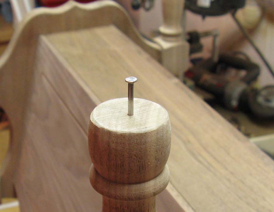
Then small holes were drilled in the top of the table ends to accept the pins, which were tapped into place, one of which is shown below. Alignment was done with everything upside-down. The pins protruded only about 1/10", so it was fairly straightforward to position the table assembly over the top based on some masking-tape positioning marks. It was then pressed into the top to mark the four holes.
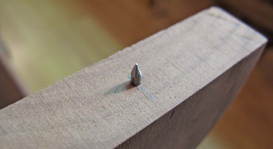
One of the alignment pins in place on the top edge of one of the table ends
These marks were used to drill the dowel holes in the bottom of the table top as shown below.
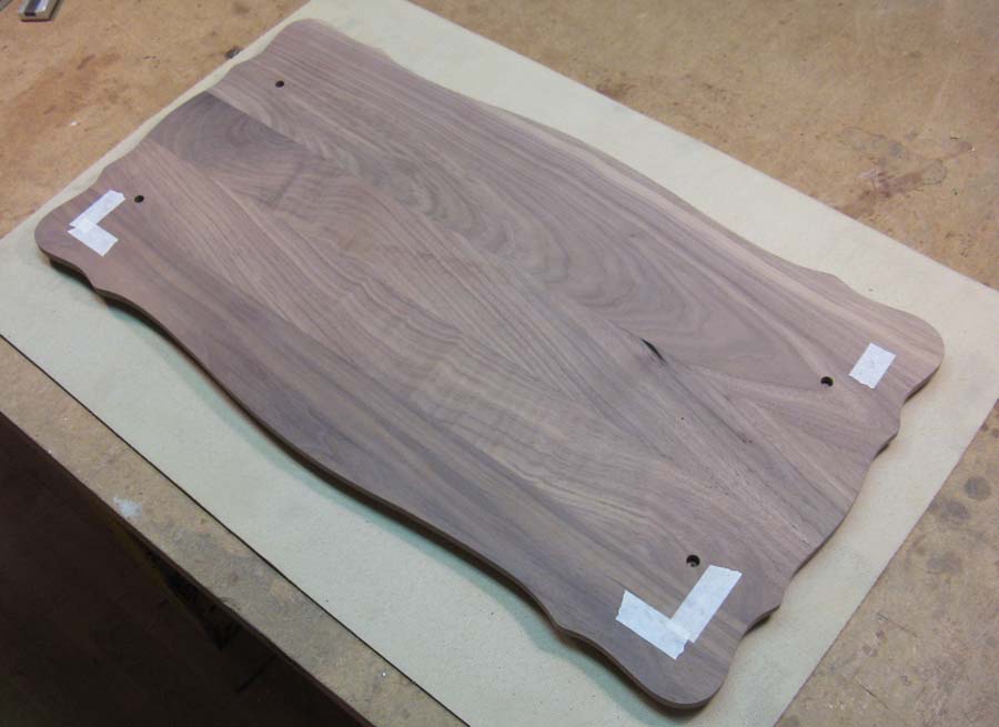
The table top with holes for dowel pins
The marking pins were removed with pliers and the table body was drilled as well, as shown below. Of course, the same multiple-pin alignment issue exists as was described before. I felt that the table could accommodate a bit of of misalignment between the two
ends since the table ends could flex, but I needed to compensate for imperfect hole spacing in each end.
The table body, with dowel pin holes, ready for assembly to the top
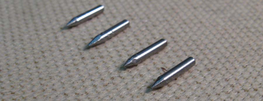
Instead of drilling oversized holes, I decided to modify the dowel pins. Below are the four dowel pins. The left two are unmodified, but the right two have most of their lengths reduced in diameter so they provide some clearance to the nominal-sized hole.
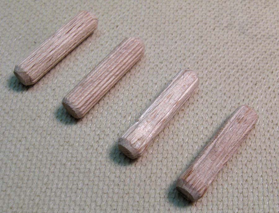
Four dowel pins, the right two of which have partially reduced diameters
The pins were just sanded down to a reduced diameter, and then some new flutes were added with a V-shaped carving tool. In the end, I don't think this technique gave much advantage over just drilling an oversized hole (especially considering the extra work involved), so I'll probably stick with the latter technique in the future.
As mentioned in the construction details of the previous table, sometimes table tops are attached in a manner that permits some size change without stressing joints. However, that isn't an issue for this particular table since the grain of the ends and top are in the same orientation and they should expand and contract similarly. That meant that the top could be directly connected to the ends, simplifying construction a bit.
I decided that pins in the buttresses wouldn't necessarily help much, so I left them off and stuck with the four dowel pins shown above. The shot below shows the top being clamped to the main body of the table while the glue sets.
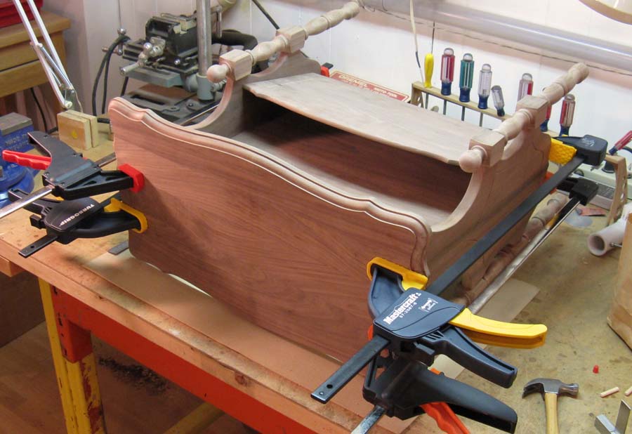
Table to being glued to the table body (on cluttered workbench)
Finishing
I used a similar finish on this table to the others; three coats of Miniwax Satin Wipe-on Poly. It was applied with a foam brush, with a small bristle brush used to get into narrow areas that the foam one wasn't able to reach.
Little nails in the feet to hold them up for finish drying
Steel wool of grade #0000 was used between the coats to roughen up the previous coat for better adhesion, with vacuuming and a
tack-cloth to remove the steel wool and finish residue.
To apply the finish, I usually start with the table upside-down, and apply finish to all the accessible surfaces, including the bottom side of the top.
To apply the finish, I usually start with the table upside-down, and apply finish to all the accessible surfaces, including the bottom side of the top.
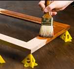
"Painter's Pyramids"
The table then gets flipped over, and I often use some small plastic "painters pyramids" to place the table on to allow the finish on the bottom of the legs to dry.
These are great little items (shown above), but they work particularly poorly for a table. They need to be aligned correctly prior to setting a table with wet finish on them, and due to that finish, there's very little friction. I've had tables slip off the pyramids, so I wanted a more secure solution. Instead, I just drilled the feet and tapped in some nails for the table to sit on, as shown above. This let most of the foot be finished, and provided a secure support when the table was sitting upright. After the finishing was complete, the nails were removed. It probably wouldn't make any difference, but I filled the holes with small walnut dowels and gave them another couple coats of finish.
The completed table is shown below.
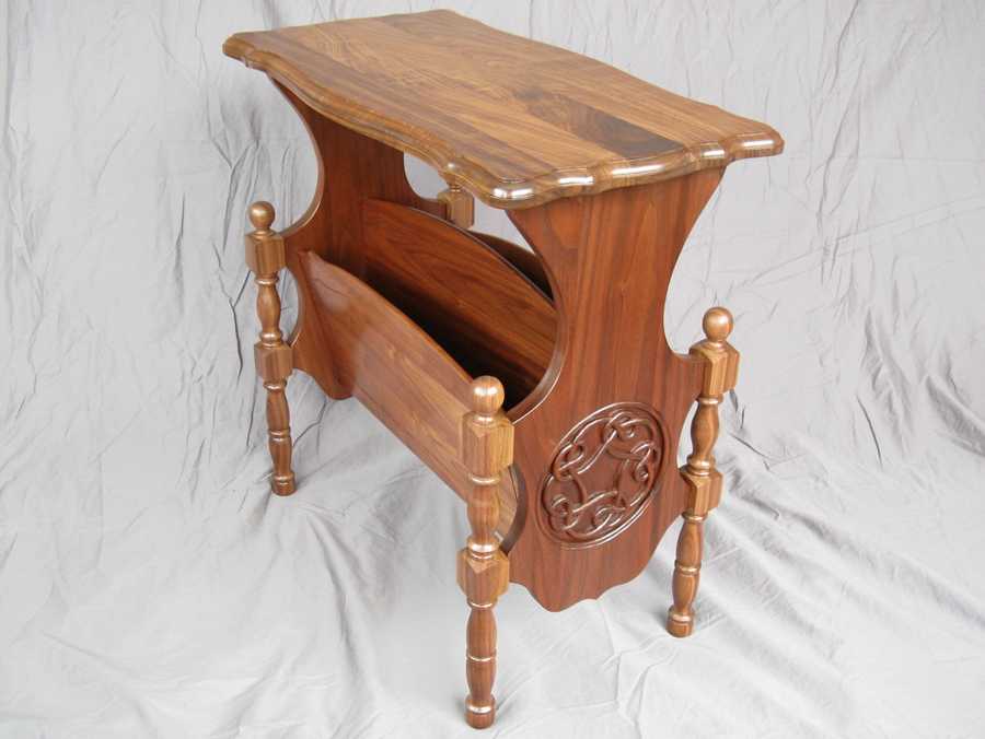
Done


