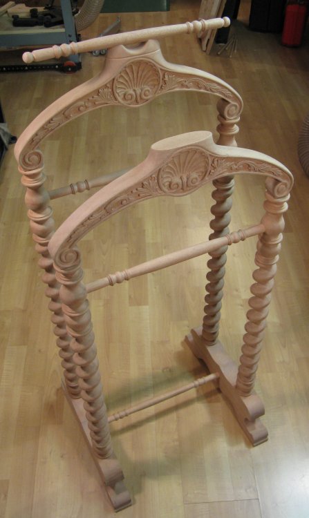
This valet was made as a replacement for a pair of white metal valets we use. They were somewhat funky and modern, but no longer matched our other bedroom furniture, such as the Chippendale-style chair or antique armoir and made-to-match headboard. I also wanted to make something with a barley twist design and this seemed like a good candidate. It was made as a double to be a bit more efficient of floor space than the current two valets.
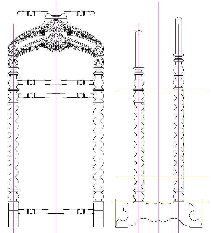
Front and side elevations
Wood
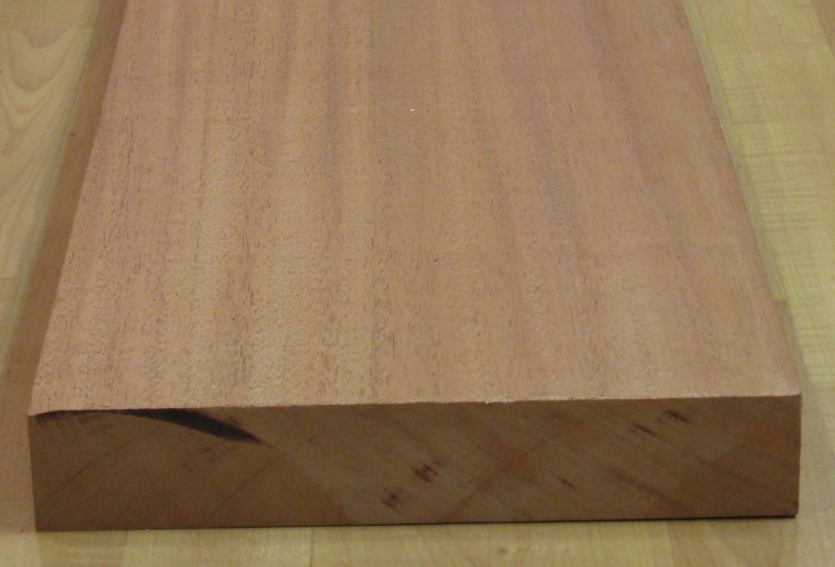
Mahogany plank
I decided to use mahogany for this project. I'm not usually a big fan of the look (perhaps from over-exposure to 60s-era mahogany doors and baseboards), but it is the classic wood for furniture and with a piece consisting mostly of curves and carvings, the grain isn't very prominent. The particular type or just the pieces of wood I used were a bit more brittle than I like. It isn't very tough and small pieces would split off with only moderate pressure - making detail carving a bit more of a challenge.
Barley Twist
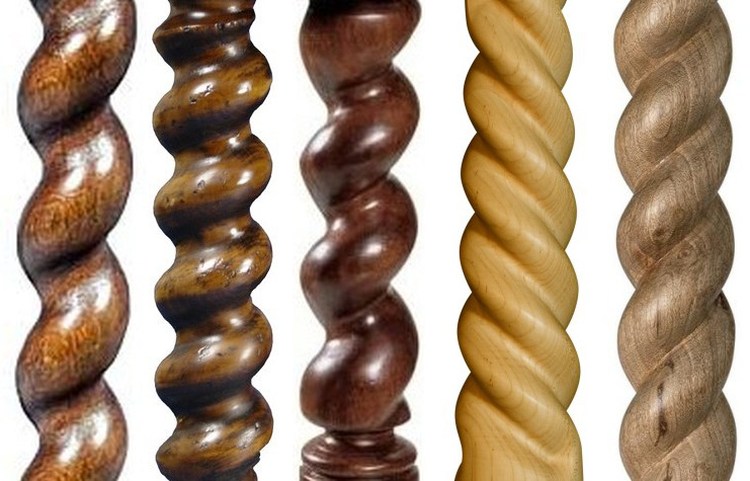
Some examples of barley twists
When planning the valet, I looked into ways to cut the barley twist shape into the spindles. Doing it by hand was an option, but that required lots of manual material removal. I've cut much smaller spirals before, and they are pretty time-consuming, so given that I had about 6 linear feet of spiral to cut in the four spindles, I wanted to avoid the manual method.
It turns out there are jigs specifically made for cutting spirals in wood. It looked like the good ones were pretty costly and hardly worth buying for one project. There was also a Sears Craftsman jig that I had never heard of before (a "Router Crafter") which would have been much more economical, but was also unfortunately obsolete. However, after a bit of searching I was surprised to find one of these obscure items for sale on eBay, and then even more surprised to also find one on the local Kijiji. It was almost odd enough to make me wonder if it was some scam that was based on my Google search terms. I mentioned this suspiciously-convenient coincidence to my woodworking brother and he said "yah, I have one of those you can use". Apparently they weren't quite as obscure as I thought.
It turns out there are jigs specifically made for cutting spirals in wood. It looked like the good ones were pretty costly and hardly worth buying for one project. There was also a Sears Craftsman jig that I had never heard of before (a "Router Crafter") which would have been much more economical, but was also unfortunately obsolete. However, after a bit of searching I was surprised to find one of these obscure items for sale on eBay, and then even more surprised to also find one on the local Kijiji. It was almost odd enough to make me wonder if it was some scam that was based on my Google search terms. I mentioned this suspiciously-convenient coincidence to my woodworking brother and he said "yah, I have one of those you can use". Apparently they weren't quite as obscure as I thought.
Jig
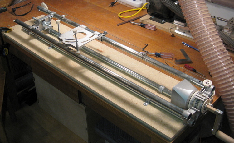
Barley twist cutting jig
The jig works by providing a crank to manually turn the spindle. The action of turning also causes a cable to pull along a router so that it mills out the wood to form the twist shape. I was curious as to how the jig could be set to cut different pitches (how tight the twist is). In fact, it cannot - it cuts one pitch and one pitch only, and that is better described as a "spiral" than a "twist".
The amount the router moves in one rotation of the spindle is determined by the diameter of the cable reel at the crank end. Since the reel diameter is a bit over 2", the pitch of the spiral is a decidedly non-thread-like 7" or so. I was looking for something closer to a 1.5" pitch, so would have needed a reel of around 0.5" diameter.
The amount the router moves in one rotation of the spindle is determined by the diameter of the cable reel at the crank end. Since the reel diameter is a bit over 2", the pitch of the spiral is a decidedly non-thread-like 7" or so. I was looking for something closer to a 1.5" pitch, so would have needed a reel of around 0.5" diameter.
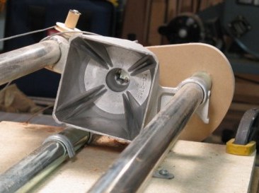
Drive end receptacle
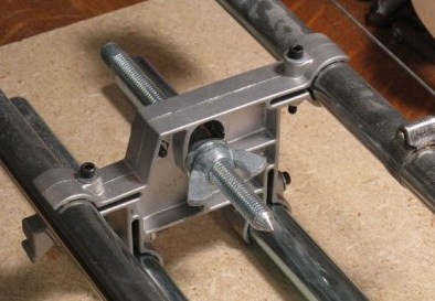
Pivot end
These shots show the crank end of the jig, with a receptacle suitable for square-ended stock - the corners fit into the slots of the receptacle, which provides a solid grip when it is turned. The other end is a simple pivot whose position is adjusted to accommodate the length of the workpiece. The pivot is adjusted to ensure the corners fit snugly into the receptacle.
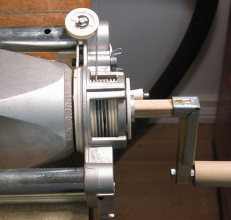
Stock crank and reel
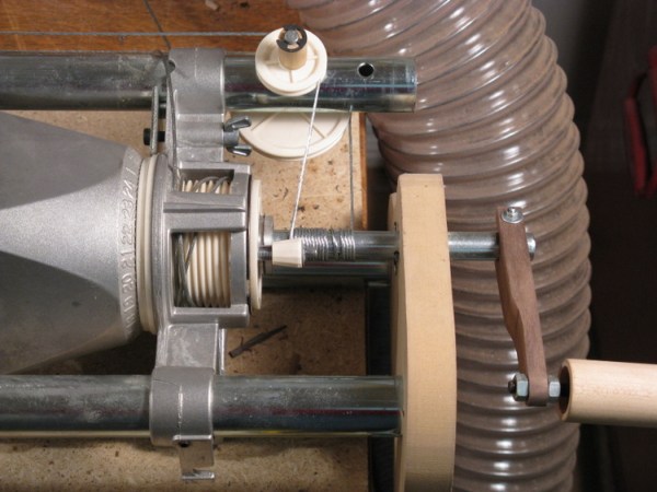
Modified crank and "reel"
Cable tensioning spring
The above shots show the regular cable reel and a modification I made to reduce the pitch of the spiral. This replaced the standard reel with a 1/2" rod (by the way, thanks for the loan, Greg. I fixed the handle I broke, and the modifications are completely reversible, I promise).
The original cable was disconnected and replaced by a shorter one. I used the smallest-diameter cable I felt I could get away with to minimize the length along the bar when it was wrapped. Whether due to the diameter or quality of the cable (intended for picture hanging) it stretched a bit during use, and the photo of the cable-tension spring to the right shows successive installations of the end loops needed to "take up the slack".
The original cable was disconnected and replaced by a shorter one. I used the smallest-diameter cable I felt I could get away with to minimize the length along the bar when it was wrapped. Whether due to the diameter or quality of the cable (intended for picture hanging) it stretched a bit during use, and the photo of the cable-tension spring to the right shows successive installations of the end loops needed to "take up the slack".
Original and modified spirals
This system worked fine, although it took some manual guidance of the cable to ensure it wrapped as a single layer on the 1/2" rod to ensure a consistent pitch. Ultimately, the pitch was about 1.7" with the new setup, which worked fine for my purposes.
This is a shot of a test spindle with shallow cuts showing both the original and new spirals.
This is a shot of a test spindle with shallow cuts showing both the original and new spirals.
Spindles
Blank spindle
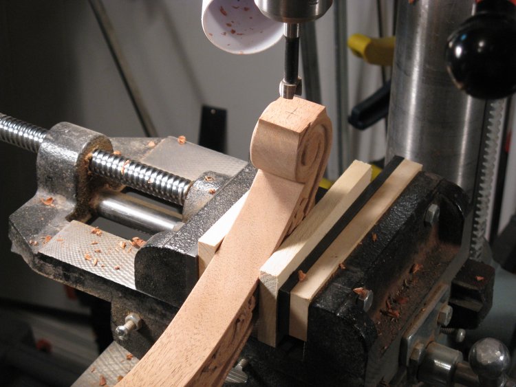
So with the jig appropriately modified, I could start on the actual spindles. I turned four blank spindles, keeping one end square to fit into the drive cup of the jig. A completed part is shown still mounted to the lathe.
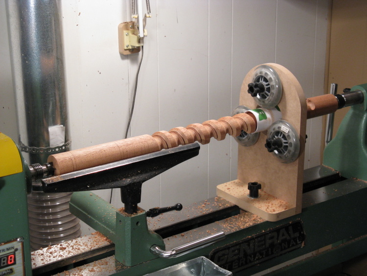
Spindle on jig
This shows a wood blank in position with the router sled flipped away from the wood. In operation, the router is started and then lowered into position to start cutting the wood. The crank is turned and the spindle turns likewise, with the router being pulled along, cutting as it goes. At the end, the router is lifted off the wood and the jig "unwound" to move the router back to the other end for the next pass.
Jig setup
This shot shows the jig set up with the router in place and a dust collection hood attached to the router sled. The depth of the cut in the wood is controlled by adjusting the sled jack screws (the ones with the white plastic knobs at the ends). My router didn't fit on the sled, so I had to borrow a more appropriate one - fortunately a handy and helpful neighbour had a Craftsman router he was willing to part with for a while (thanks Les), which of course mated nicely with the Craftsman jig.
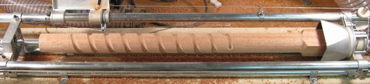
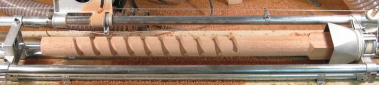
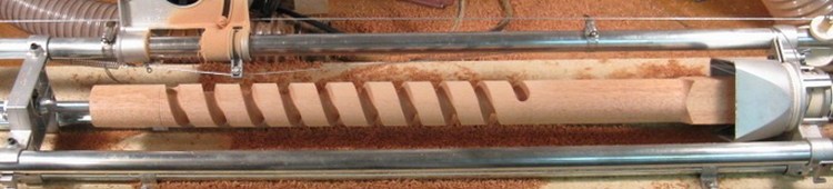
Successive passes of router
I had been warned and it also became apparent that the jig wasn't precise enough to cut the final shape of the spindle, so it was used for bulk material removal. After some experimentation with various shapes and sizes of bits, I settled on a combination that seemed to work well. I started with a core-box (bull-nose) bit to cut the spiral to the appropriate depth. Three successive cuts were used to get to the proper depth, and then a 45 degree chamfer bit was used in a couple more passes to ease the corners of the resulting slot.
On all of the passes except the last, the router is pulled from the pivot end to the crank end. However, to cut the opposite side of the slot, the direction needed to be reversed so the router bit was cutting with the grain to prevent tear-out.
This series of shots shows the effect of successive passes - three individual passes with the core box bit and then after the two passes of the chamfer bit.
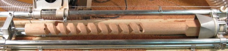
Roughed-out shape
And this is the resulting profile. The shape that the jig produced still needs a fair amount of shaping work to get to the final round profile.
Spindle ready for turning
The next step was to turn the ends of the spindle before finishing the twist portion. The theory here being that if I messed up the turning (always a possibility) then the finishing time would have been wasted. In the event, I was good 4 for 4 spindles so it wasn't necessary to make any new ones - although there was an extra spindle blank "on deck" in case it was needed.
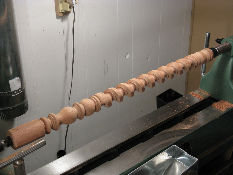
This shot shows the spindle just off the twist-cutting jig. It's fairly long and doesn't have a lot of wood in the twist section, so a shop-made jig supports it near the middle. I used a piece of slotted plastic pipe to tightly hold the twist portion and give the (skateboard) wheels a nice smooth surface on which to spin.
This shot shows the spindle just off the twist-cutting jig. It's fairly long and doesn't have a lot of wood in the twist section, so a shop-made jig supports it near the middle. I used a piece of slotted plastic pipe to tightly hold the twist portion and give the (skateboard) wheels a nice smooth surface on which to spin.
Turning done
Here the decorative turning at both ends is done, and smoothing the twist is next up.
The twist section of the spindle needed ridges in the slot smoothed down and the outside portion rounded. I started by using carving chisels on the ridges, but that was pretty time-consuming. Given that there was about 25' of ridge to remove all told, that called for something a bit more efficient. The solution was to use a rotary tool with a flex shaft to sand off the ridges. To get an appropriate sanding bit, a small drum-sander intended for drill press use was modified so it would fit a Dremel.
The twist section of the spindle needed ridges in the slot smoothed down and the outside portion rounded. I started by using carving chisels on the ridges, but that was pretty time-consuming. Given that there was about 25' of ridge to remove all told, that called for something a bit more efficient. The solution was to use a rotary tool with a flex shaft to sand off the ridges. To get an appropriate sanding bit, a small drum-sander intended for drill press use was modified so it would fit a Dremel.
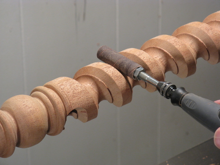
Sanding off ridges
This next sequence of rather staged-looking shots illustrate the steps for twist smoothing.
As mentioned the ridges were sanded off using a small drum on a flex-shafted Dremel. This worked well, and also gave the opportunity to blend the round-bottomed slot with the start of the top bevel.
As mentioned the ridges were sanded off using a small drum on a flex-shafted Dremel. This worked well, and also gave the opportunity to blend the round-bottomed slot with the start of the top bevel.
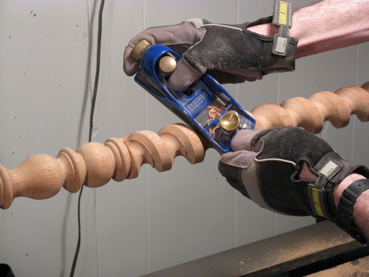
Further bevelling corners
The corners were given another couple stages of bevel on their way to being rounded by using a block plane. With the spindle mounted on the lathe, I was actually able to set it to rotate slowly and just let the plane ride along at the proper angle, cutting as it went. I couldn't get right to the ends, but it did everything else very efficiently.
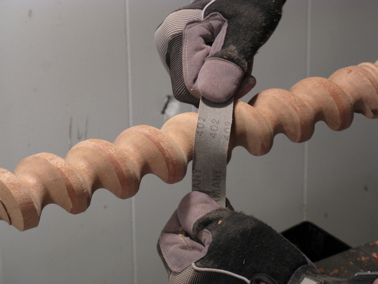
Hand sanding
The last step was hand-sanding to smooth off all the facets and blend all the surfaces. It didn't help to spin the lathe for this, so I just used strips of sandpaper pulled back and forth by hand.
The sandpaper strips were cut from belt-sander belts (which use a fabric backing) since they are strong and the abrasive is long-lasting. Regular paper-backed sandpaper tends to rip if you pull too hard.
The sandpaper strips were cut from belt-sander belts (which use a fabric backing) since they are strong and the abrasive is long-lasting. Regular paper-backed sandpaper tends to rip if you pull too hard.
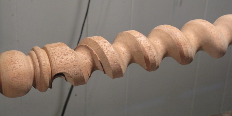
Progressive finishing steps
This shot shows the progressive stages of smoothing. From left to right, the first turn is straight off the cutting jig, the next one has the ridges sanded off, the next the extra bevels cut and the last has been sanded smooth.
The spindles also needed some additional carving to complete the twists at the end. At the left of this photo the round end of the routed slot is visible. This needed to be extended and tapered down to the end as can be seen in the shot of the completed spindles a couple photos below.
The spindles also needed some additional carving to complete the twists at the end. At the left of this photo the round end of the routed slot is visible. This needed to be extended and tapered down to the end as can be seen in the shot of the completed spindles a couple photos below.
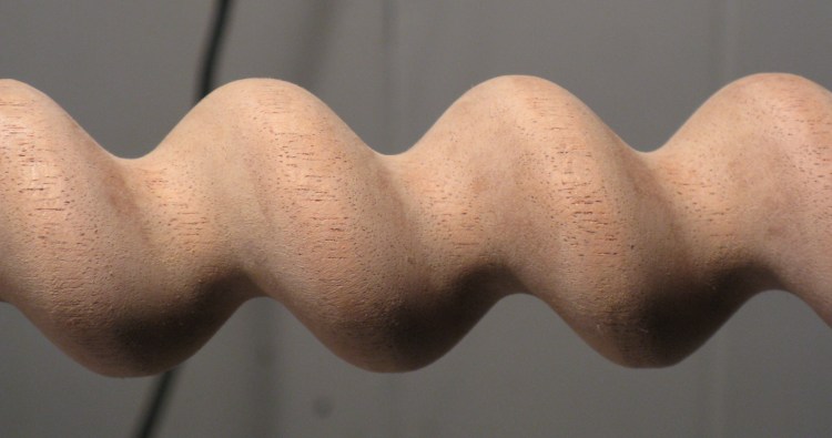
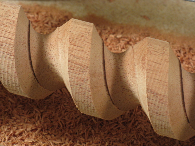
Completed barley twist detail
This is a detail of the completed barley twist section with the sanding done.
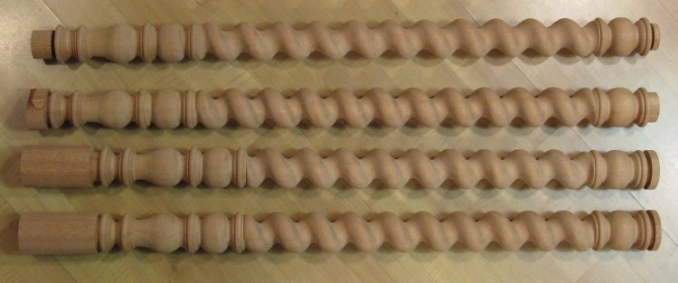
Completed spindles
This shows the set of 4 spindles, complete except for the ends.
Once the jig had been modified and set up and the technique finalized, the routing of the spindles took only about an hour per. However, getting them to the finished state took about another 6 hours per spindle.
Once the jig had been modified and set up and the technique finalized, the routing of the spindles took only about an hour per. However, getting them to the finished state took about another 6 hours per spindle.
Hangars and Feet

8/4 mahogany for hangars and feet
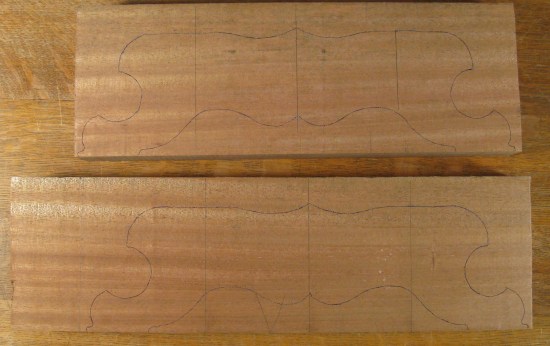
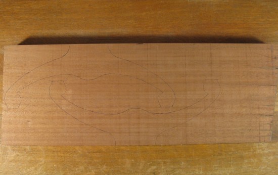
The next stage was to cut out the hangars and the feet. To start, the shapes were transferred from full-sized plans to the planks as shown below.
Feet
Hangar pieces
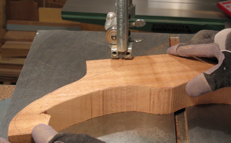
Bandsawing one of the hangars
The pieces were then cut out close to the lines with a bandsaw.
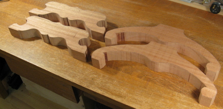
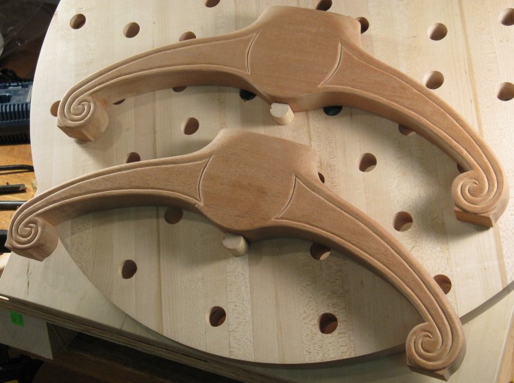
Feet and hangars cut out
With the resulting shapes shown here.
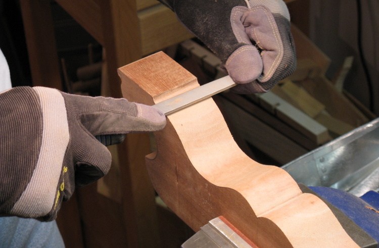
Shaping one of the feet
The pieces were then more closely shaped to the desired profile, mostly with a drum sander and some hand work for the smaller areas.
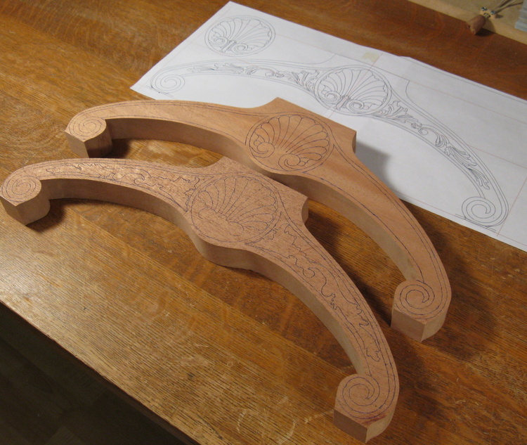
Tops marked
After the hangars were brought to the finished overall shape, it was time to set them up for carving. This shot shows various portions of the pattern copied on to the hangars.
To transfer patterns, I usually use a pin awl to pierce through the lines of the pattern into the wood, and then connect the dots with a pen. I started with that technique and it isn't bad for long lines, but for detailed sections, poking through 3 km of lines (I'm guessing here) is pretty time-consuming.
So to do the details on the hangars, I instead dug out some old carbon paper and traced the pattern with a pen. Unfortunately for some reason the lines weren't very easy to see, but perhaps it was due to the carbon paper being more than 30 years old. However, it turns out they still make the stuff, so after a trip to the local Staples I used some fresh obsolete technology and got nice dark lines.
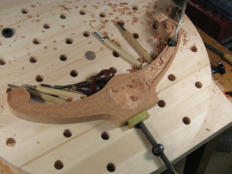
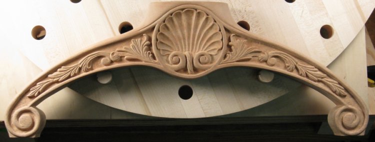
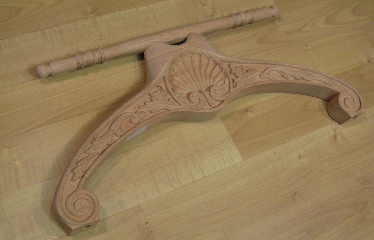
Early stages of carving
Here one of the hangars is in the beginning stages of carving. The basic shape has been roughed out on one side, and the center "shell" portion has been mostly excavated to the proper profile.
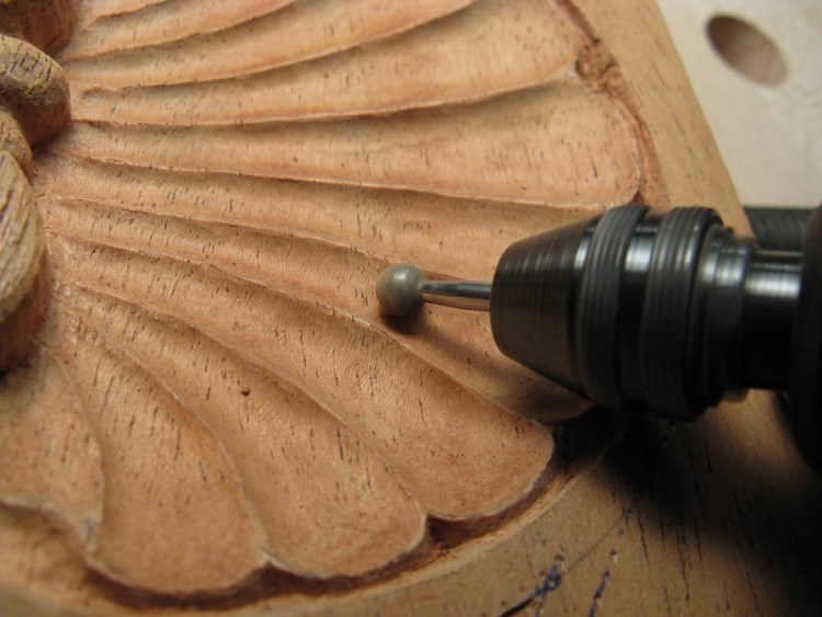
Smoothing the shell section
The shell portion in the center presented a bit of a challenge due to the ridges between the concave sections of the shell design. Since the grain was across the ridges, their triangular cross-sections consisted of decreasing-length fibers of wood that had little strength. I found the thin edges weren't strong enough to handle the cutting action of even a very sharp chisel, so I ended up carving so that the ridges were left about 1/16" thick, and then using an abrasive sphere to complete the final shaping as shown here.
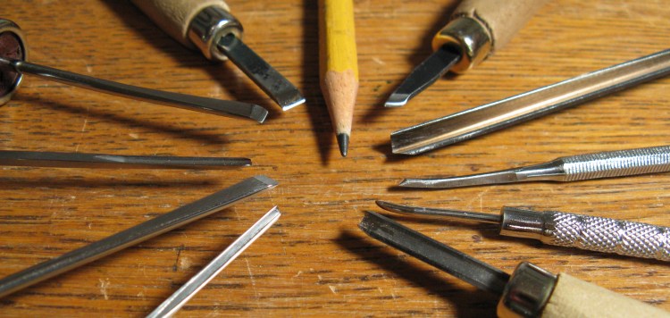
Miniature carving tools
I had a couple sets of miniature tools, but it turned out that I needed some that were even "miniaturer" since some of the detail was pretty tough to do with what I had on hand.
The four tools on the left are from a new set, and the others are the "legacy" tools. There are a couple reworked dental tools on the right used for even smaller details.
The four tools on the left are from a new set, and the others are the "legacy" tools. There are a couple reworked dental tools on the right used for even smaller details.
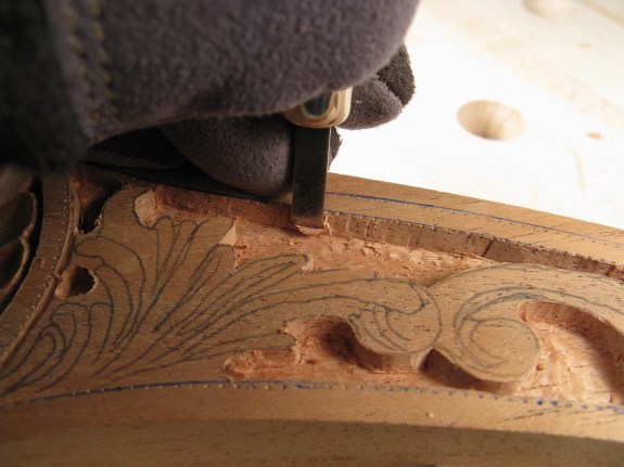
Trimming edges with larger chisel
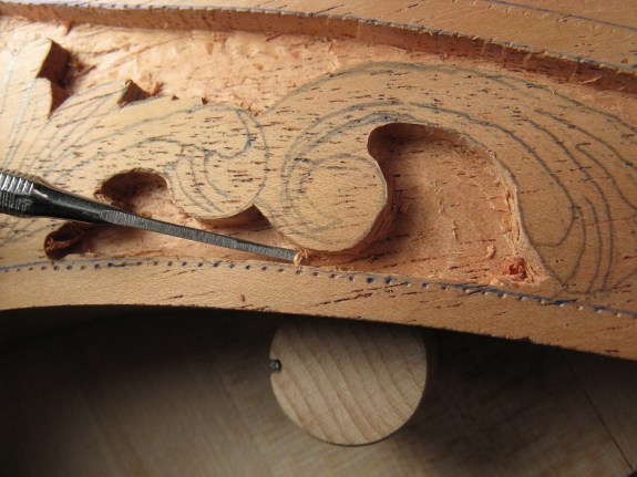
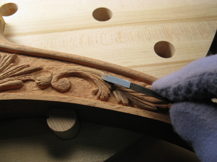
Cutting slot with narrow chisel
Honing a larger gouge
The two photos above show a couple of these tools at work. The narrow chisel was specifically made to cut the slots at the edges. It's about 0.05" wide, so I could slice down at the edges of a slot with the wider chisel and then clear out a strip of wood maybe 0.02 to 0.03" thick with the narrow one, and repeat this process to the bottom.
I started by outlining the pattern and clearing out the wood down the "ground" level, which is largely complete in the above shots. The larger areas were cleared using a Dremel cutting bit in a drill press to give a consistent depth. Hand carving followed to get closer to the pattern and the edges. After that, the sections were contoured and shaped.
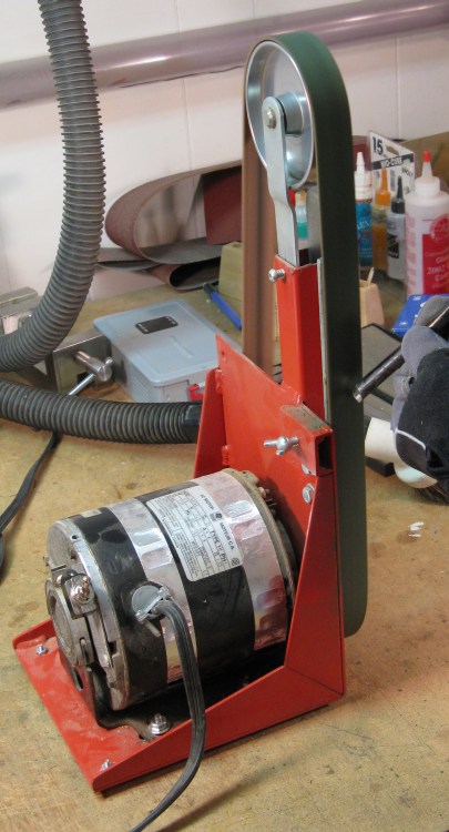
The tools were kept sharp using a powered leather belt as seen to the side here. The belt gets "charged" (rubbed with) a block of honing compound to add a fine abrasive and then the tools are held against the belt for a few seconds to bring them to razor-sharpness.
I started by outlining the pattern and clearing out the wood down the "ground" level, which is largely complete in the above shots. The larger areas were cleared using a Dremel cutting bit in a drill press to give a consistent depth. Hand carving followed to get closer to the pattern and the edges. After that, the sections were contoured and shaped.
The tools were kept sharp using a powered leather belt as seen to the side here. The belt gets "charged" (rubbed with) a block of honing compound to add a fine abrasive and then the tools are held against the belt for a few seconds to bring them to razor-sharpness.
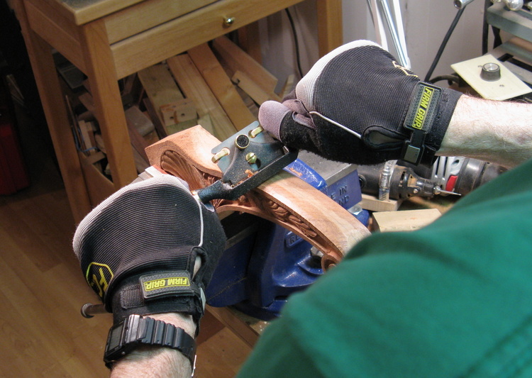
Sanding some detail bits
The carved "foliage" sections needed sanding to smooth out the contours. This was mostly done with small sanding jigs like this picture shows. A quick-drying latex cement was used to glue 220 grit sandpaper onto appropriately shaped jigs like this one. The sandpaper could easily be peeled off and replaced after a couple minutes of sanding. The gloves keep moisture and skin oil off the wood.
Contouring the top edge
The profile of each hangar had been left square to simplify clamping of the piece for carving. With that complete, the edges could be contoured. That was done with a combination of rasps, files, sanding and a spokeshave as shown in the photo.
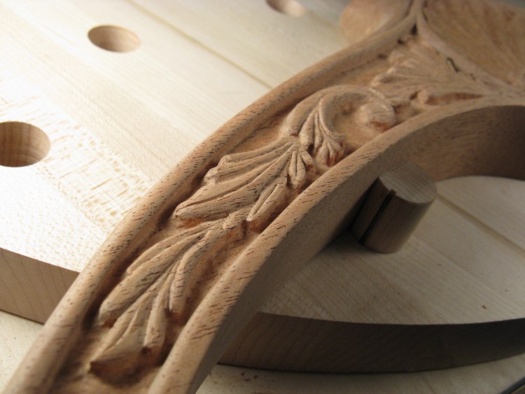
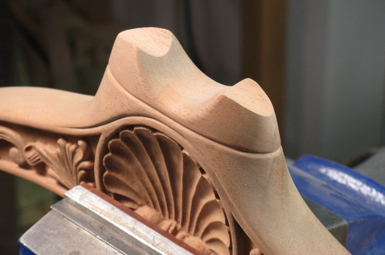
Detail of one end
This is a closeup of one end of the first hangar. I thought it was completed, but after looking at this photo, I decided that it needed a bit more sanding in a few spots.
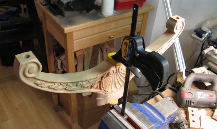
Completed hangar
This is one of the hangars after being completed.
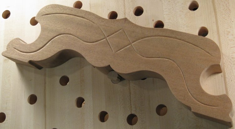
Back side of hangars
It took over 40 hours to carve the detail into each of the hangars, so I didn't think giving the backs the same treatment was warranted. Instead, they got a simple decorative groove that reflects the wing outlines on the front. This shot shows the backs.
Foot detail
The feet got a similar treatment with a decorative groove on the sides facing out to add some visual interest. This is one of the feet, post-grooving.
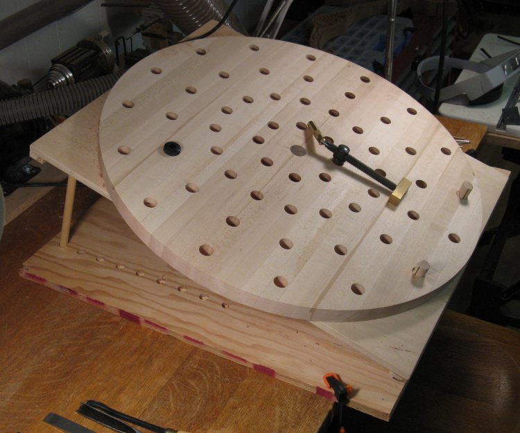
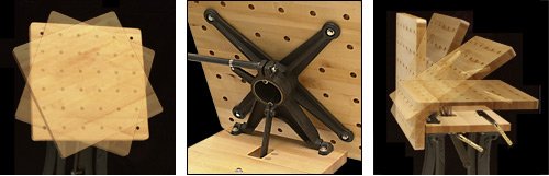
Carving table
As an aside, this photo shows the carving table that appears in the background of several of the pictures above. I built it in anticipation of spending a fair amount of time on hand carving in this project and thinking that it would be useful to rotate the workpiece. I was certainly correct on the first count but the second, not so much.
The top was actually inspired by a painfully expensive Lee Valley product. That one has a square top with a large and sophisticated cast-iron support permitting the rotation and angle adjustment. To accomplish similar adjustments, my table was made to permit the vertical angle to be adjusted by means of simple support rods (at the left of the photo), in concert with a front piano hinge. This worked pretty well and gave a nice solid base to work on. The top was made from laminated maple and included the 3/4" holes for bench dogs and clamp mounting points, drilled with the aid of a buddy with a deep-throated drill press (thanks Gary). The top was built to be pivoted on a central spindle - the brown piece of walnut seen at the center. The theory was that the piece to be carved could be clamped to the table, and then it could be rotated to permit carving at different angles. Well, this turned out to be wrong in an embarrassingly obvious manner.
The top was actually inspired by a painfully expensive Lee Valley product. That one has a square top with a large and sophisticated cast-iron support permitting the rotation and angle adjustment. To accomplish similar adjustments, my table was made to permit the vertical angle to be adjusted by means of simple support rods (at the left of the photo), in concert with a front piano hinge. This worked pretty well and gave a nice solid base to work on. The top was made from laminated maple and included the 3/4" holes for bench dogs and clamp mounting points, drilled with the aid of a buddy with a deep-throated drill press (thanks Gary). The top was built to be pivoted on a central spindle - the brown piece of walnut seen at the center. The theory was that the piece to be carved could be clamped to the table, and then it could be rotated to permit carving at different angles. Well, this turned out to be wrong in an embarrassingly obvious manner.
Slick. If you have $725 to commit.
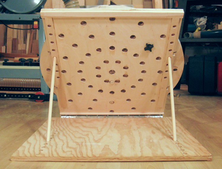
Here are some shots of the table that inspired mine. In lieu of custom metalwork, my cunning plan was to use a round table with a radial pattern of holes. The support board that permitted vertical angle adjustment was drilled in a similar radial pattern to match the top holes, and a 1/16 rotation (22.5 Degree) would have the holes lining up again - I figured that was adequate resolution. What I failed to anticipate was that the clamps and other holders penetrate both the top and the support board, so of course you can't rotate it without first removing all the clamping and support pieces. Doh!
Hey, look - those bench dogs go right through...
The black piece is a plastic-ended nut that fits on a bolt from the other side to lock the top in place.
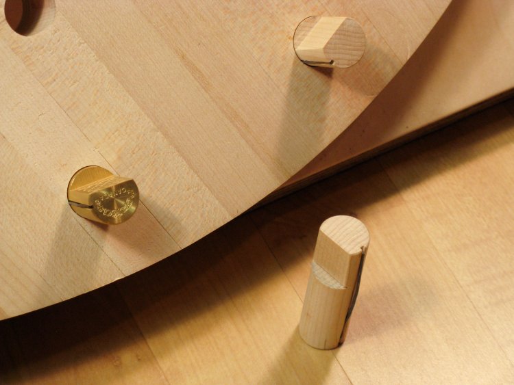
"Wonder pup" and shop-made bench dogs
However, other than that trivial little matter, the table still worked pretty well. And in lieu of more of the nice solid brass "wonder pups", also from LVT, I made a couple of my own short bench dogs from maple, more to avoid a drive to the other end of town than any particular fiscal economy on my part. They worked just fine, and while not as strong as the metal versions, were more than adequate to hold the workpiece for hand carving. I imagine if I was using a big chisel and a mallet, more clamping force and tougher bench dogs might be necessary.
All in all it worked pretty well, and while a rectangular grid of holes would likely be a bit more versatile for clamping, I figure my round top looks rather cooler than the square version, so I can't complain.
And now back to our regularly scheduled programming...
All in all it worked pretty well, and while a rectangular grid of holes would likely be a bit more versatile for clamping, I figure my round top looks rather cooler than the square version, so I can't complain.
And now back to our regularly scheduled programming...
Rods and Assembly
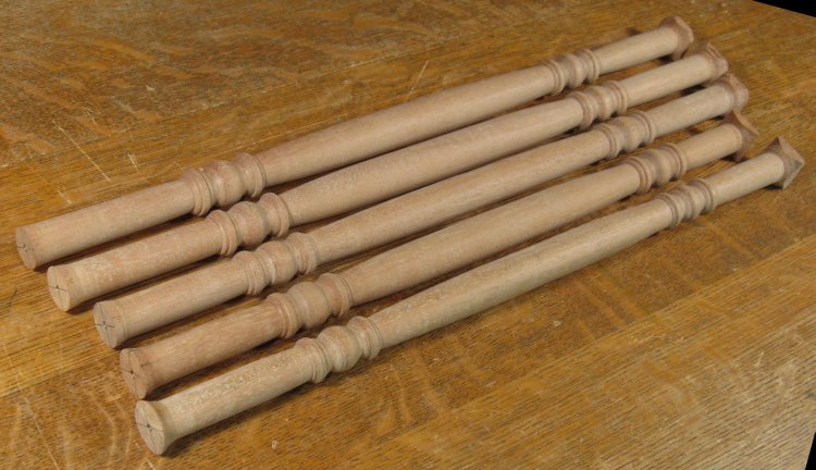
Hangar rods
The (almost) last pieces to be made were the rods to hang the clothes over. After the rather glacial-seeming progress of the carving, these were rather a relief. The valet needed 3 or 4, but I made 5 so there was a spare and I could pick the best ones. All told, it took just over 4 hours to make the blanks, turn them and sand them.
Drilling top to fit on spindles
So with everything made and carved and shaped and sanded, it was time to look at assembly. In general, dowels are used to hold things together. This is a shot of drilling the bottom portions of one of the hangars to accept a dowel.
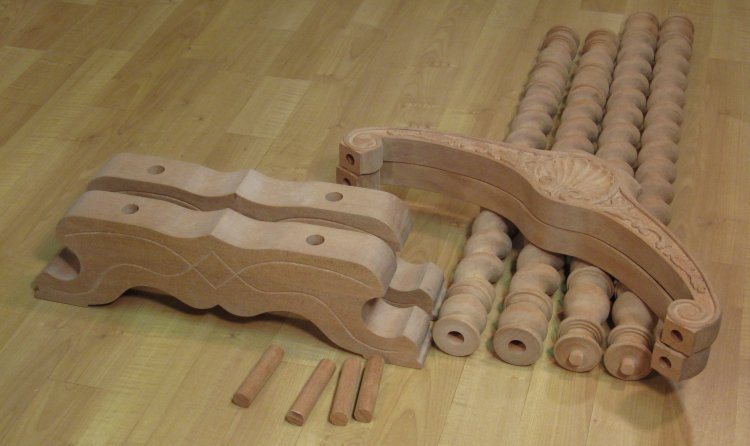
Pieces ready for assembly
And this shows all the pieces ready to go (inexplicably minus the rods). The tops of the spindles have dowels turned in them to mate with the hangars. That might well have been a better strategy for the bottoms as well, but there wasn't sufficient length to accomplish that, so instead I drilled the bottoms of the spindles and made matching dowels. The rods fit into appropriate holes drilled in the spindles and the feet.
Just a bit on the top, please
It turned out that I wasn't quite done. The original plan was to have a flat-bottomed rod on top of the taller hangar, but it ended up that I didn't like the rather plain look. Instead, I decided to use one of the extra rods I had lying around so it would match the rest. The ends were cut off and rounded, and a then a mount needed to be added to the hangar. This shot shows an extra piece of wood being glued to the top of the hangar.
Rod mounting piece
This shows the finished rod mount, contoured to match the rod. The glue joint with the hangar has been carved to match the other grooves and help make the joint less obvious.
Completed for sure this time
Finished top hangar with rod attached by means of glue and 1/4" splined dowels.
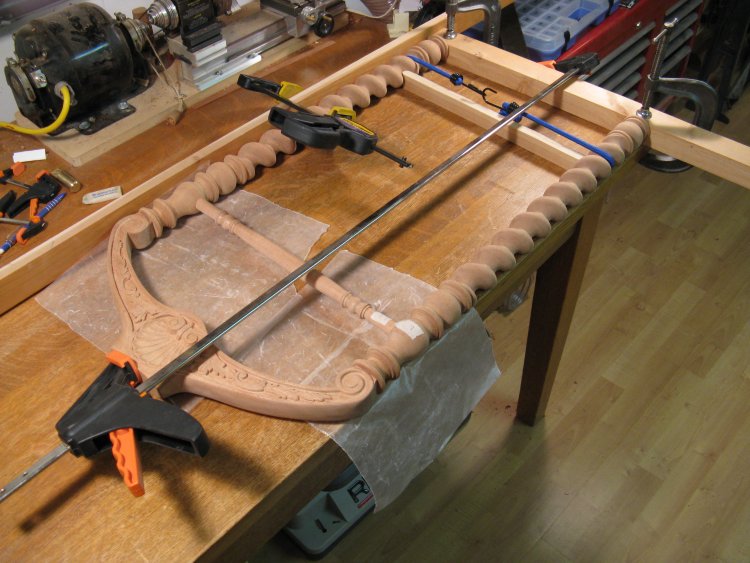
Assembling and gluing one of the sections
The assembly was done in stages; First assemble the two sets of spindles/rod/hangar, then the feet to its rod, and finally each hangar assembly to the feet.
This shot shows one of the hangar assemblies being glued and clamped. The wood frames on the outside are to ensure squareness, and the wood between the spindles with the bungee cord make sure the spacing is correct.
This shot shows one of the hangar assemblies being glued and clamped. The wood frames on the outside are to ensure squareness, and the wood between the spindles with the bungee cord make sure the spacing is correct.
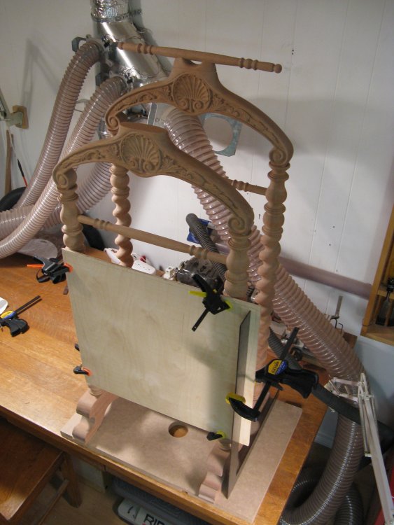
Adding the second section to the feet
This is the final stage of assembly where the last hangar assembly is being glued to the feet. The thin plywood board provides a flat surface and allows the metal square to hold things at the proper angle.
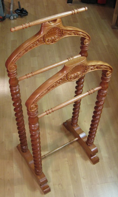
And finished.
And...it's done.
Completed.


