I gave the vessel a mostly-cyllindrical shape with three feet and a pointed bottom. That provided lots of "display area" for the decorative dots and the Ornamental Crab wood is pretty light in colour which helps with the contrast. I had originally thought that I might need to dry the wood as was done with the first piece made from this log, but after three years of basement dwelling it seemed to have dried out enough to work with.
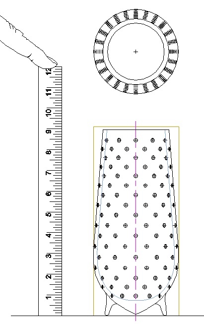
The plan
Beginning the Body
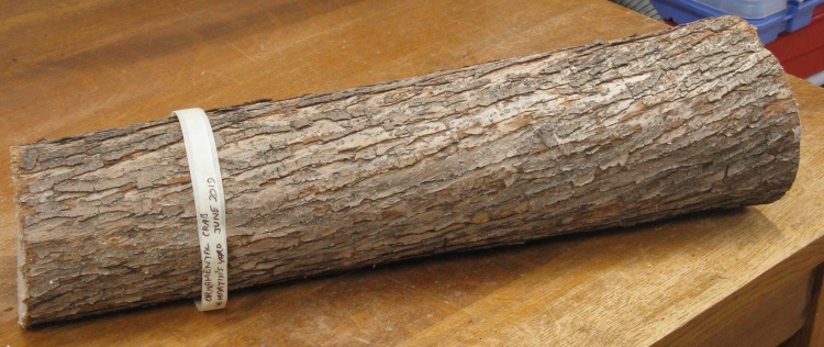
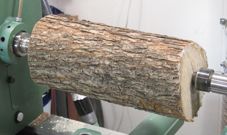
A couple feet of Ornamental Crab trunk
This photo shows the trunk piece I started with. The ends had been sealed with wax to slow the moisture loss and that must have worked properly since the ends were crack-free.
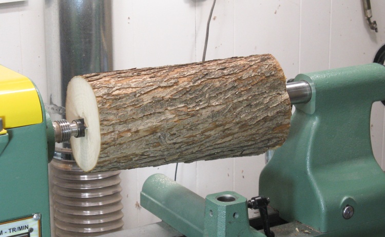
Mounted to the lathe
I needed only about half the length so the bandsaw was employed to cut it in two and I used the end with the slightly larger diameter.
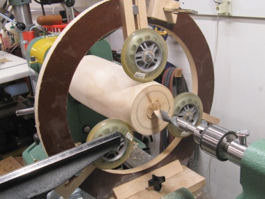
Here it's been mounted to the lathe between centers so it can be rounded and the ends trued up.
Here it's been mounted to the lathe between centers so it can be rounded and the ends trued up.
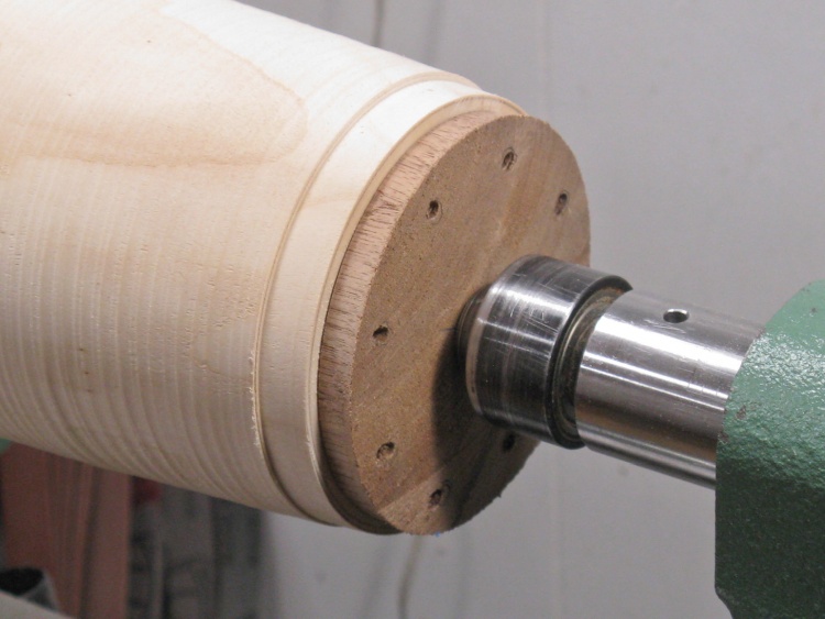
A few minutes with the roughing gouge removed the bark and resulted in a round blank (plus of course the usual huge friggin' mess in the workroom) with the diameter left oversized in case it needed to be force-dried. Then the ends were trued up so the faceplate would mount squarely.
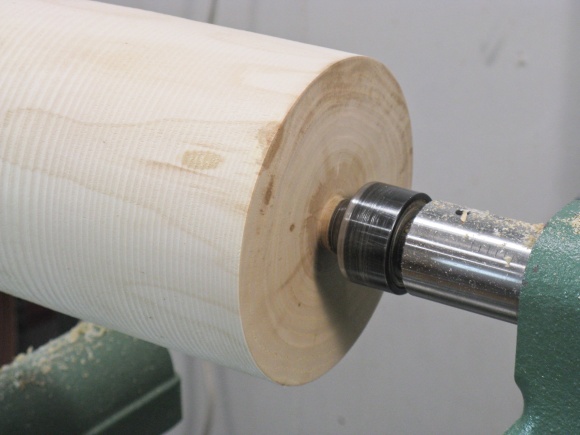
Bark off & end flattened
Attaching the faceplate
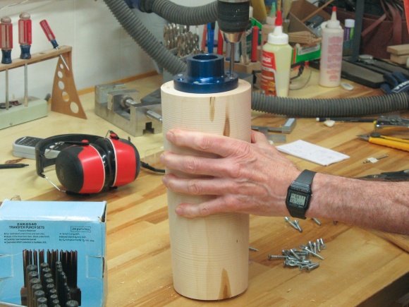
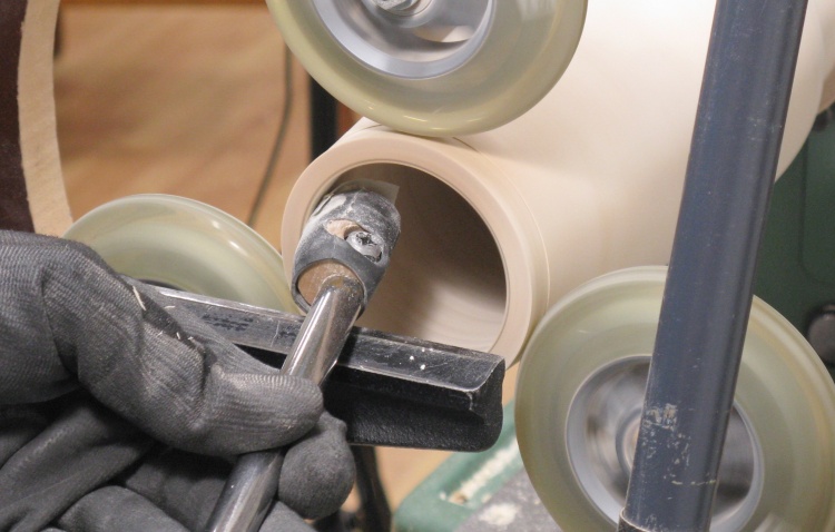
After a bit more outside shaping I switched to doing some initial hollowing of the vessel. For that I added the large brown steady-rest to stabilize the mouth-end of the vessel and started by drilling out the center. I began with a medium-length 5/8" bit, then switched to a longer (but only 1/2" diameter) bit to drill to the full hollowing depth. Finally I used a larger-but-shorter Forstner bit to enlarge the hole for the first four inches or so (drilling being much faster than hollowing).
I actually tried an even larger Forstner bit but the hardness of the wood generated enough torque to twist the chuck loose off it's shaft. So I concluded that the hole was probably large enough...
I actually tried an even larger Forstner bit but the hardness of the wood generated enough torque to twist the chuck loose off it's shaft. So I concluded that the hole was probably large enough...
Drill #1

Drill #2
Drill #3
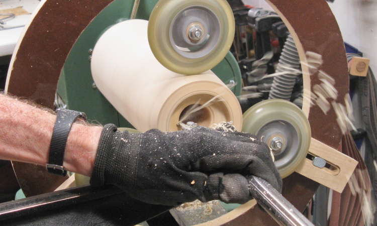
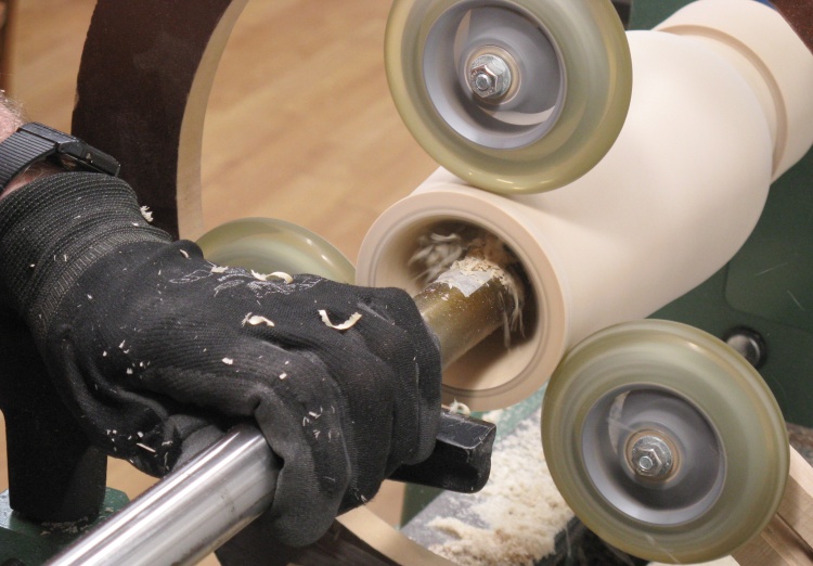
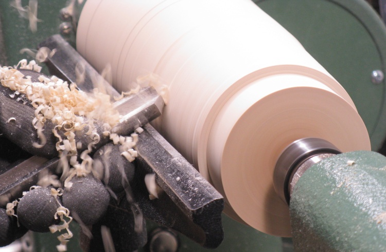
Starting the hollowing
Then I got on with the hollowing using my usual captive hollowing tool. You can see shavings shooting off the tiny carbide cutting disc on the end of the shaft.
End plate added for support
The outside of the wood had seemed fairly dry but often the inside has more moisture. However in this case, the inside was pretty dry as well so that meant that I didn't need to dry it out any further (I had used a microwave oven to do that when I made the leaf-top vessel from the green log).
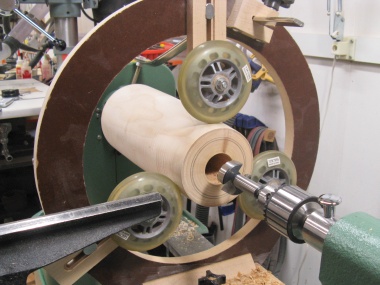
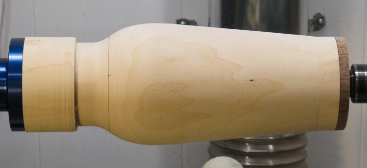
That let me switch back to a conventional turning sequence; outside first, then the inside. For support of the open end so I could return to outside turning, I made a little disc to fit exactly into the opening so it could be stabilized with the tailstock live center as seen here.
That let me switch back to a conventional turning sequence; outside first, then the inside. For support of the open end so I could return to outside turning, I made a little disc to fit exactly into the opening so it could be stabilized with the tailstock live center as seen here.
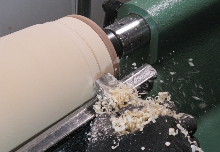
Shaping the outside
Gratuitous flying-chips shot of shaping the outside with a roughing gouge.
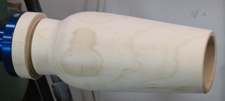
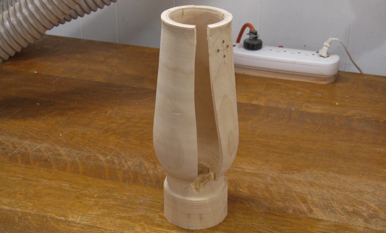
Outside shaping done
The outside shaping is done in this shot. The bottom (left side) will later be formed into feet while the straight section at the top is extra and will eventually be removed.
Working on the hollowing again
Then it was back to the hollowing. I was aiming for walls of about 0.2" thickness.
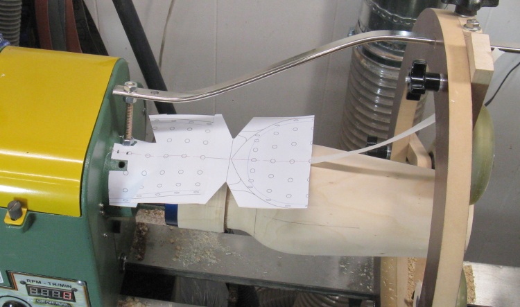
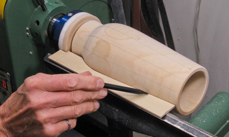
Adding plan to aid hollowing
It was a bit tricky locating the cutter position when cutting near the bottom since the large foot section made it difficult to use the laser position indicator.
To help with that I positioned the plan above the spinning piece to better guide the cutter near the bottom.
To help with that I positioned the plan above the spinning piece to better guide the cutter near the bottom.
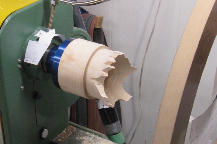
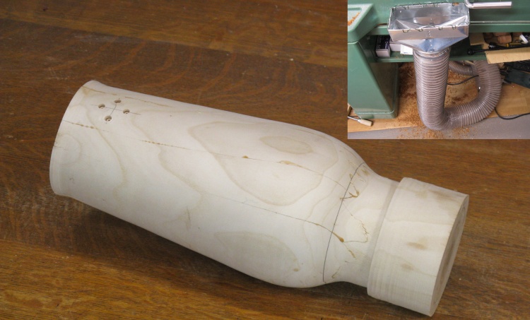
Oops
Unfortunately as I was smoothing the very bottom I experienced a "catch" and the whole vessel exploded off the lathe, leaving this jagged nub.
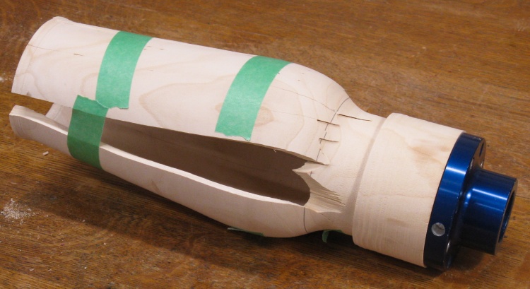
And it all came back except one tablespoon*
So I gathered up the pieces and taped them together in the proper order but even after recruiting Sue's help, we couldn't find that last bit. Not that it matters but it's just more satisfying to have all the pieces.
I've repaired exploded pieces in the past but that wasn't really practical in this case even if I'd had all the pieces.
*This was a line from a Crisco commercial in the 70s purportedly showing how little oil is absorbed by your fried chicken. However as pointed out by an astute buddy of mine, the chicken releases unknown amounts of water and fat as it cooks so obviously any before-after comparisons are meaningless.
If at first you don't succeed...
Fortunately I had the remaining piece of the log so I stuck it on the lathe and did 'er again.
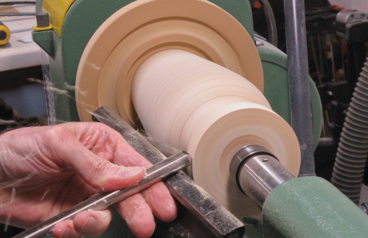
Doing the outside shaping
I didn't need to check the moisture level this time so I could use the regular turning sequence. Here I'm working on the outside shaping.
Made it to the sanding stage
I finished shaping the outside and then the inside was successfully hollowed as confirmed by this shot showing the inside being sanded.
I suspect the rotation speed may have been too high first time around (maybe 1050 RPM which would generate around 35 Gs of pull-me-apart force at the vessel walls). I lowered the speed for this redo and was also quite careful when using the cutter that caused the problem the first time.
I suspect the rotation speed may have been too high first time around (maybe 1050 RPM which would generate around 35 Gs of pull-me-apart force at the vessel walls). I lowered the speed for this redo and was also quite careful when using the cutter that caused the problem the first time.
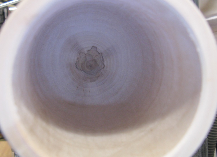
Inside done
The inside looked decent after sanding and the growth rings are even nicely centered at the bottom.
...And outside done (except feet)
The shaped outside is shown here.
I thought it would be best to mark the dot positions while the vessel was still on the lathe, so that was the next step.
I thought it would be best to mark the dot positions while the vessel was still on the lathe, so that was the next step.
Planning the Pattern

Square or diamond? That is the question.
The vessel as originally drawn had a square grid of dots (mostly since it was easier to draw on the plans) but I wondered if a diamond pattern might look better.
So I whipped up a 3D model to get a better look at the options. To my eye the diamond pattern looked more interesting so I decided to go with that.
So I whipped up a 3D model to get a better look at the options. To my eye the diamond pattern looked more interesting so I decided to go with that.
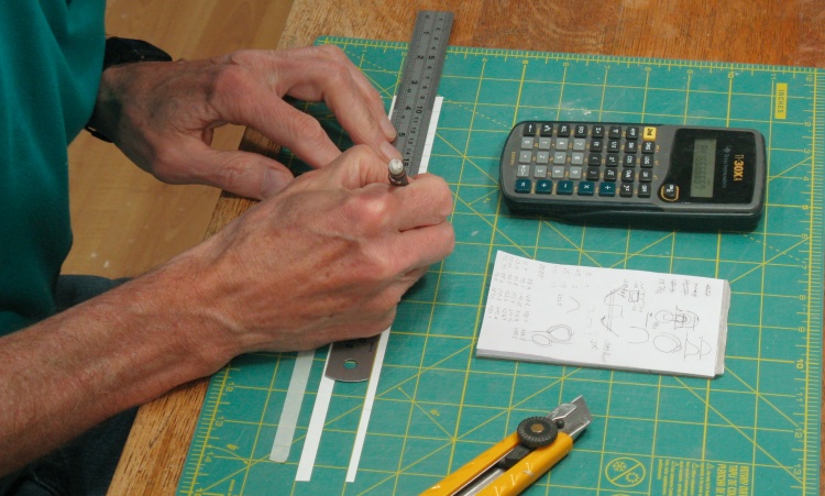
Marking tape for 24 divisions
To get the side dimension of the diamond shapes to be near the 3/4" I was aiming for, it turned out that there needed to be about 24 vertical lines of dots and those lines needed to be marked on the vessel.
I wrapped some white tape around each end and marked the overlaps to get the exact circumferences, then pulled them off and through the Magic Of Division (really, the Magic Of The Electronic Calculator) marked 24 equal spaces for each end.
I wrapped some white tape around each end and marked the overlaps to get the exact circumferences, then pulled them off and through the Magic Of Division (really, the Magic Of The Electronic Calculator) marked 24 equal spaces for each end.
Marking the first set of top-to-bottom lines
The plan was to draw a line from end to end using the tape markings as a guide and a contoured piece of thin plywood as a ruler but that didn't work out very accurately.
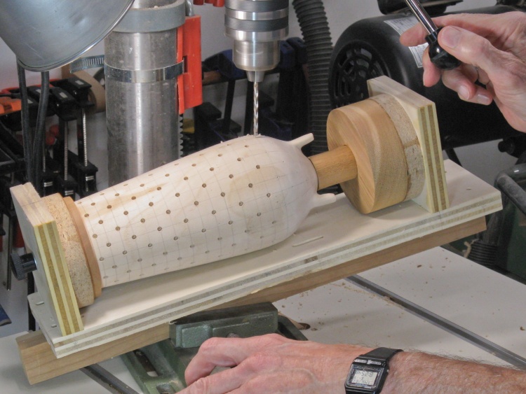
So I erased those lines and switched to Plan B which took advantage of the lathe's shaft positioning feature which lets the shaft be locked at one of 12 angles. I simply locked it at each angle and drew a line as this photo shows. While that worked well, it gave me only half the lines I needed.
So I erased those lines and switched to Plan B which took advantage of the lathe's shaft positioning feature which lets the shaft be locked at one of 12 angles. I simply locked it at each angle and drew a line as this photo shows. While that worked well, it gave me only half the lines I needed.
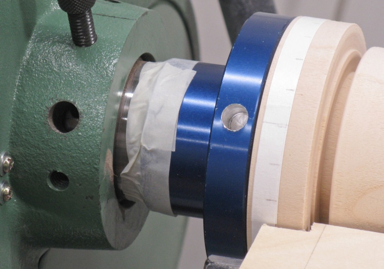
Taped 1/24 of a turn looser
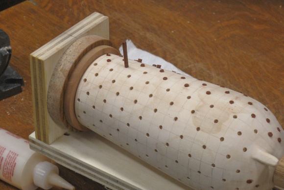
To get the other 12 lines that were halfway between the first set, I loosened the faceplate 1/24 of a turn (just done by eye) and taped it to the shaft to hold that offset. Then once again I rotated the shaft by 1/12 turns and drew the other 12 lines.
The shaft angle is locked by threading in the black bolt seen to the upper left in this shot.
The shaft angle is locked by threading in the black bolt seen to the upper left in this shot.
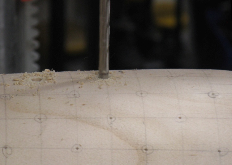
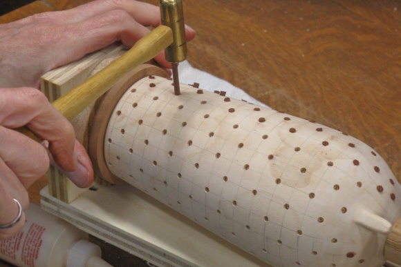
I also added lines for the vertical locations of the dots. I started 1/4" from the top and then at each position down the vessel I used a vertical spacing equal to the horizontal line-to-line spacing at that position. That kept the dots in an even diamond pattern at different vessel diameters.
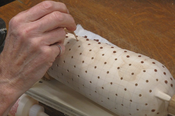
Once all the lines were drawn, I marked the dot positions in the diamond pattern, and then used an automatic center punch to make a divot at each location. I'll later drill holes to accept short pins of contrasting-colour material for each dot.
Once all the lines were drawn, I marked the dot positions in the diamond pattern, and then used an automatic center punch to make a divot at each location. I'll later drill holes to accept short pins of contrasting-colour material for each dot.
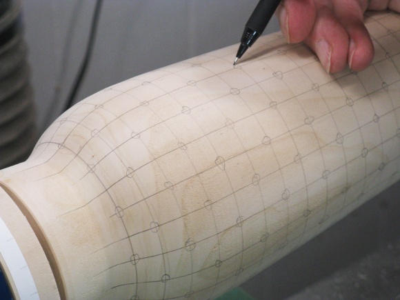
Designating the appropriate intersections
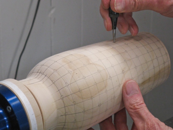
Center-punching hole locations
Fabricating the Feet
Flipped and now working on the bottom
With the pattern marked out, the vessel turning could be finished off.
I made a jam chuck to hold the top then removed the faceplate and flipped the vessel around to access the bottom. This photo shows the extra wood past the bottom being removed. I then proceeded to cut a ring for the feet and shape the pointy bottom of the vessel.
I made a jam chuck to hold the top then removed the faceplate and flipped the vessel around to access the bottom. This photo shows the extra wood past the bottom being removed. I then proceeded to cut a ring for the feet and shape the pointy bottom of the vessel.
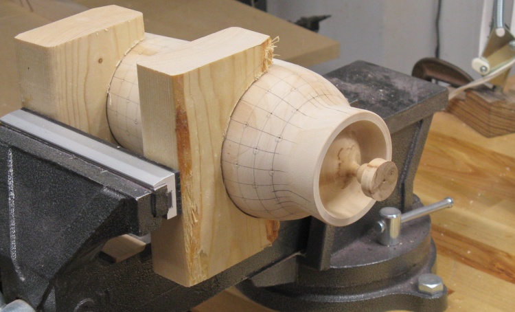
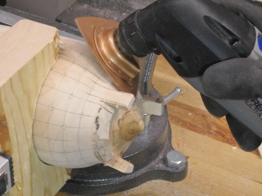
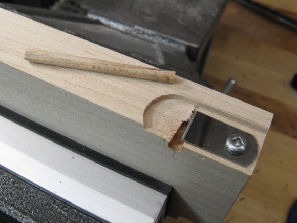
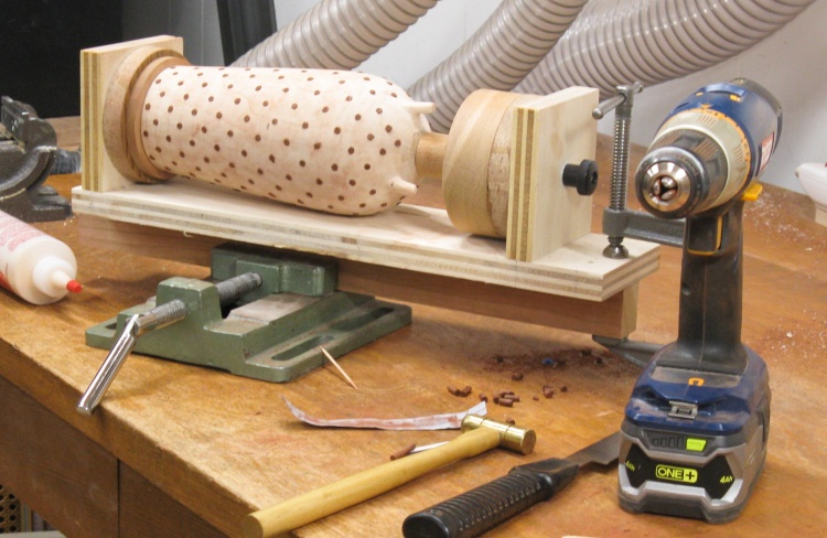
Bottom done and vessel mounted in vise
This shows the bottom shape after pulling the wood off the lathe.
The bottom ring will be shaped into a set of three feet and the center nub will be removed.
The bottom ring will be shaped into a set of three feet and the center nub will be removed.
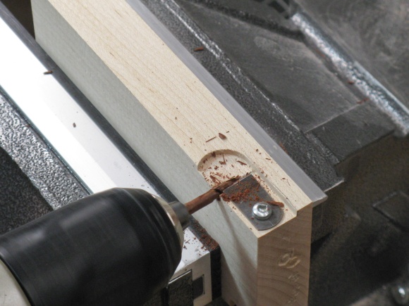
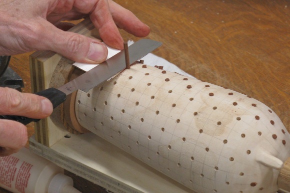
I started the feet by cutting through the ring at the edges of the three feet. The Dremel Multi-Max (AKA Oscillating Tool) equipped with a saw blade was used for the cuts. The same tool with a narrower blade was used to cut out the bulk of the ring sections between the feet.
Cutting to define feet
Removing between-feet sections
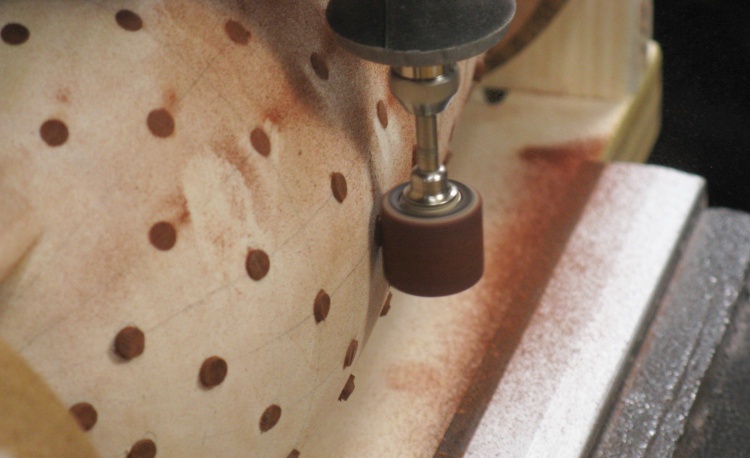
Bottom could use a bit of cleanup
The bottom looks a bit rough at this point and the main focus will be to smoothly blend together the areas above and below the feet.
Much of the coarse shaping was done with the multi-tool again, this time with an abrasive plate installed. That was followed by some drum sanding and finally with some sandpaper-equipped sticks to blend the curves.
Coarse sanding
A bit of drum work

...and some stick sanding
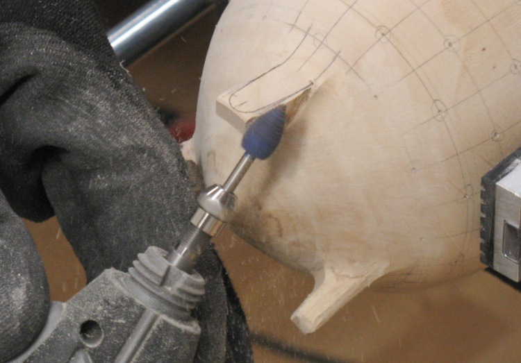
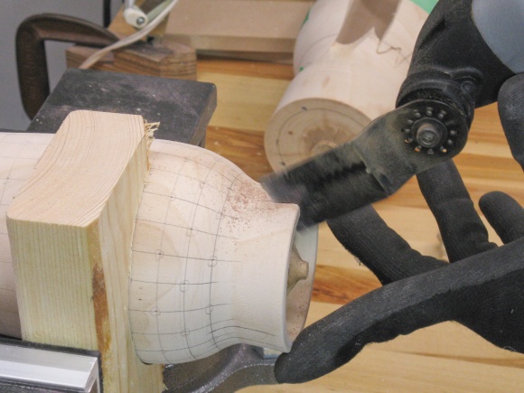
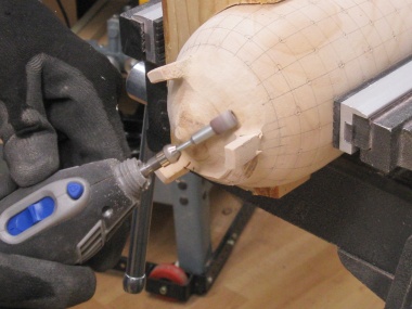
Shaping one of the feet
The feet were still rectangular from the crude cutting-out operation, so they were shaped with a burr as seen here, followed by drum sanding.
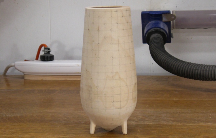
Vessel with the feet mostly shaped
The feet will need a bit more attention but this shows the basic shape of the vessel.
Decorating with Dots
First-try pieces were glued together to use as test subject
I glued together the shards from the first version to use as a test piece for making the dots.
That missing piece still bugged me and I made a few half-hearted attempts to try to find new places to look for it, but with no success.
That missing piece still bugged me and I made a few half-hearted attempts to try to find new places to look for it, but with no success.
Ah-Ha! Found the missing piece
It finally ocurred to me that the missing piece could be in the dust collection system. I straightened out the 5" hose that goes to the lathe and sure enough a few feet back I could see the piece - Wohoo!
So I pulled it out of the hose and glued it in too.
So I pulled it out of the hose and glued it in too.
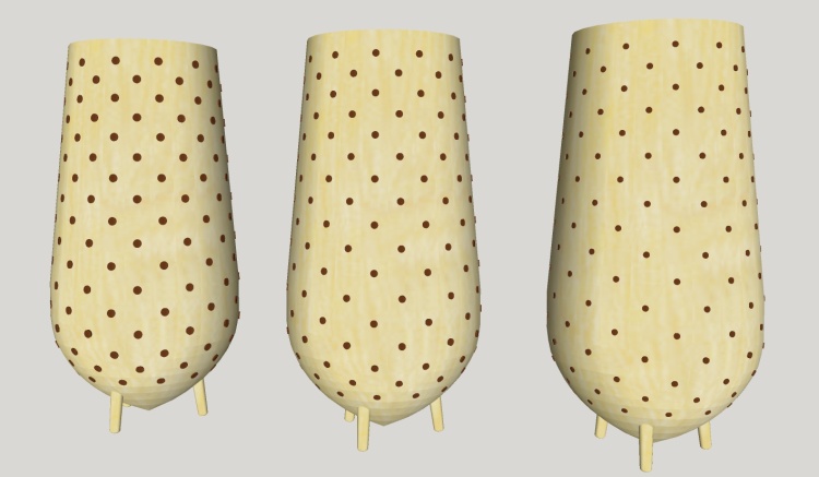
Dot size comparison (3/16", 5/32" & 1/8")
I had drilled some 3/16" holes in the test piece but then wondered if they were maybe a bit too large. So it was back to the 3D modelling program to try out the look of some different dot sizes.
I had the classic Goldilocks reaction, finding the 3/16" diameter on the left too large but the 1/8" on the right too small. The 5/32" version in the middle was just right.
I had the classic Goldilocks reaction, finding the 3/16" diameter on the left too large but the 1/8" on the right too small. The 5/32" version in the middle was just right.
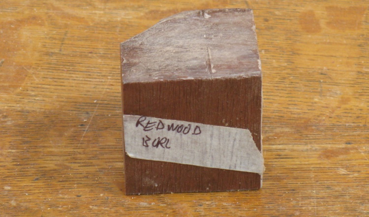
A little block of redwood burl to use for the dots
I wanted reddish dots without obvious grain and found the ideal wood in a small block of Redwood Burl on my exotic wood shelf.
I had picked it up in the mid 90's and had used another part to turn a little toothpick holder.
The block is only about 2" on a side but I just needed a fraction of that for the dot material.
I had picked it up in the mid 90's and had used another part to turn a little toothpick holder.
The block is only about 2" on a side but I just needed a fraction of that for the dot material.
The only practical approach to the dots is to make a dowel and place small lengths of it in the vessel holes. Most dowel-making methods start with a closely-sized octagonal rod so that there's less material to remove to get it round.
I started by cutting a flat piece of redwood which was then sliced into square-sectioned rods. The rods were made octagonal by placing them in a small holding jig and using a plane to flatten out the corners.
I started by cutting a flat piece of redwood which was then sliced into square-sectioned rods. The rods were made octagonal by placing them in a small holding jig and using a plane to flatten out the corners.
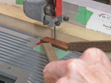
Cutting into square rods
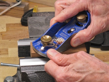
Planing off the corners
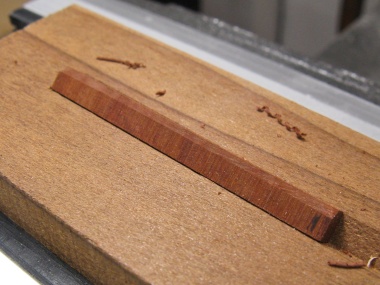
Top corner planed off
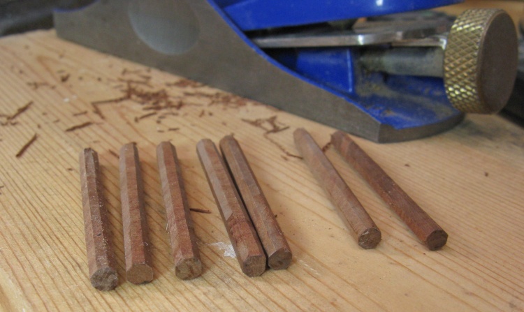
A few of the octagonal dowel blanks
This shows the first set of octagonal rods. I used perhaps three times as many to do the whole vessel.
The holes at 5/32 were 0.156" diameter and the octagons were slightly larger but somewhat variable at 0.160" to 0.170" across the flats.
The holes at 5/32 were 0.156" diameter and the octagons were slightly larger but somewhat variable at 0.160" to 0.170" across the flats.
I thought I'd try the classic dowel-trimmer approach and whipped up a jig using a maple block with the end of a hacksaw blade ground to form a cutter. This actually worked great on a piece of maple but the redwood turned out to be too brittle and just crumbled and snapped rather than being trimmed round.
A totally excellent 5/32 dowel cutter
...that doesn't work with the redwood
As a slightly desperate alternative I thought I'd try just sanding the spinning octagonal rod with 180 grit sandpaper and to my surprise that actually worked well. I had to kind of iterate to achieve the proper diameter but the dowel came out quite circular in cross-section.
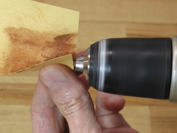
Sanding the octagonal blanks
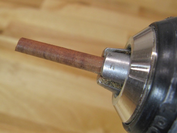
...which worked surprisingly well
The test dots on the original vessel
So then I went back to the test piece and glued in four dots, let them dry and sanded them flush. Unfortunately the Ornamental Crab is porous enough that the Redwood dust gets into the pores and colors the wood.
So instead of sanding I tried scraped them flush with a card scraper, and that ended up looking better. The results were pretty decent with that technique so I figured it was safe to start on the real vessel.
So instead of sanding I tried scraped them flush with a card scraper, and that ended up looking better. The results were pretty decent with that technique so I figured it was safe to start on the real vessel.
Jig to hold vessel for "dotting"
A jig used for a previous vessel was dug out of the jig box and modified by adding ends appropriate for this vessel shape.
Vessel mounted
This shot shows the vessel mounted in the drilling jig.
Starting to drill the holes
I made the holes using the drill press as seen here. I had added a narrower board to the bottom of the jig so it could be held with a drill press vise.
The jig was set to the angle where the drill would go in square to the wood.
The jig was set to the angle where the drill would go in square to the wood.
Marked bit used as depth guide
I wanted holes about 0.1" deep and started out by using a drill stop on the bit. However it tended to get clogged with sawdust and would sometimes mar the wood as it contacted.
Eventually I just marked off the 0.1" depth on the brad-point drill bit using a fine felt marker and drilled down to that line.
Eventually I just marked off the 0.1" depth on the brad-point drill bit using a fine felt marker and drilled down to that line.
Tilting to drill lower holes
I changed to the appropriate angle for each ring of holes, except I couldn't do the lowest two rings as they needed too much tilt. Those were bored using a cordless drill.
I left the vessel in the drilling jig for the next operation: dot insertion.
I started each dot by checking the fit of the dowel - I wanted it snug in the hole.
- If it was loose I removed a bit of dowel and tried again until it was snug or I ran out of dowel.
- If it was too large it got sanded a bit more until it fit correctly.
- Then using a toothpick I added glue to the hole and
- Tapped the dowel in until it bottomed out.
- Finally, I cut the dowel off just slightly above the surface and moved on to the next one.
Test fit of dowel
Adding glue to hole
Tapping in the dowel
Cutting off the excess
All 225 dots done
It didn't take as long as I had expected to place all the dots - maybe a day and a half of effort.
Sanding dots down a bit
The dots stuck out perhaps 0.02" to 0.07" which was too high to easily use the card scraper. So I reduced the protrusion using a sanding-drum-equipped Dremel until they were almost flush.

Scraping the surface even
Then after sharpening up a scraper, I used that to work the surface until the dots were flush.
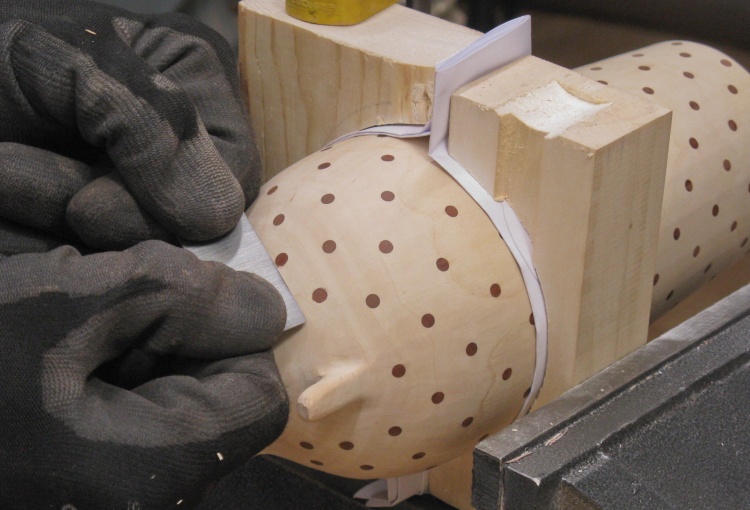
A smaller scraper for the bottom areas
There wasn't much room down between the feet so I used a small scraper on the lowest dots.
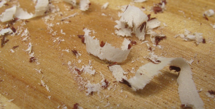
Some interesting shavings
The scraper took off shavings that were 1.5 to 2.5 mil thick and here a few of them are seen amidst the other sawdust on the main bench.
Woodworking done
A bit more finishing sanding on the feet and the woodworking was done.
Due to the lack of an actual bottom or in fact any other inconspicuous surface on this vessel, I wasn't able to add the normal initials and year.
Due to the lack of an actual bottom or in fact any other inconspicuous surface on this vessel, I wasn't able to add the normal initials and year.
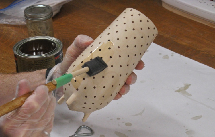
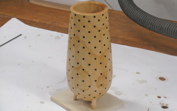
Applying the first coat of varnish
This photo shows the first coat of varnish going on. The foam brush still has the handle extension I taped on to be able to reach to the inside bottom of the vessel.
First coat of varnish on
This shot shows the first coat of varnish as it is busy drying.
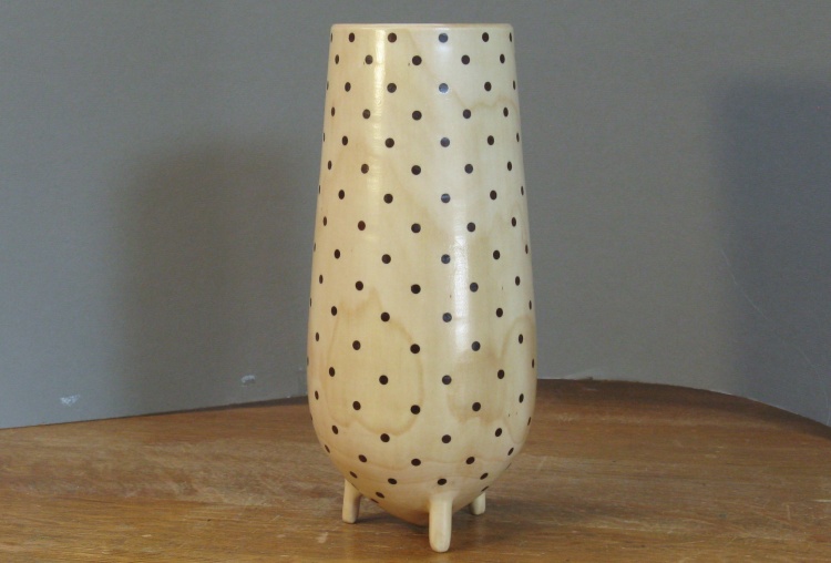
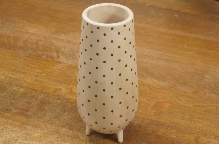
Done
Complete.
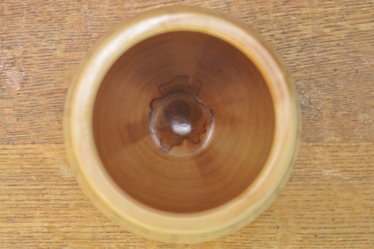
The view inside
This shot inside shows the darker core of the wood.


