I had seen a carving that reminded me of structural steel, although I'm not sure that was supposed to be what it looked like. It had sort of a black, early-20th century gothic-ish look to it that I found attractive. I thought I would try to make a piece that had a similar metal look to it. Since I was breaking in a new lathe, it made sense to make some type of vessel, and the idea for the "Pressure Vessel" was born. I also decided I liked carving more than turning, so I used the lathe to make a blank to which I added carved details.
As usual, I started out with a plan that I could use to investigate design ideas, and then also use to print out 1:1 templates for cutting and carving.
As usual, I started out with a plan that I could use to investigate design ideas, and then also use to print out 1:1 templates for cutting and carving.
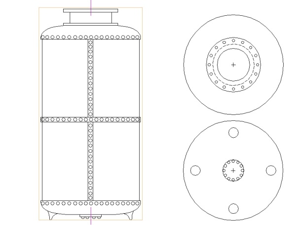
The plan
Wood
Since I was planning to dye the piece, I didn't need a nice grain. I chose maple since it would take the dye well and is a tight-grained wood with small pores - better for that metal look - and would also hold detail fairly well, which I needed for the "rivets". Maple is actually difficult to stain consistently, but that does not seem to apply when dye is used. I've used black aniline dye on maple successfully on several occasions.
The built-up blank
Usually, when making a carved or turned piece, the grain of the wood is an important feature, and that generally means using a single piece so that the grain is continuous over the piece.
But that wasn't the case here since the joins between wood pieces would be mostly hidden by the finish. Instead I used three 2"-thick planks laminated together for the turning blank. The misalignment of the three glued-together pieces that can be seen in the photo was intentional, to make sure some edges with bad wood were on the parts that I would be removing.
It turned out that there was still a hidden crack that wasn't obvious until the part was turned, but it only appears on the bottom, and isn't particularly obvious.
Shaping
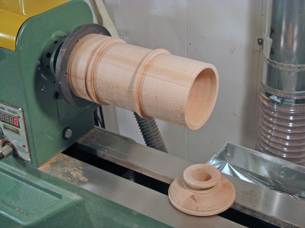
I wanted to be able to work on the end of the wood, which meant using a faceplate rather than turning between centers. For that length and weight of wood, I used a 6" metal faceplate with some fairly hefty screws. To get a secure hold, the end of the blank was recut to ensure it mounted flat and square to the faceplate. I had made sure the blank was long enough so that I could discard the portion with the screw holes. Four #10 wood screws were used to hold the piece, but since pilot holes were used, the screws didn't need their points or the full taper at the end of the screws. So I ground off the first 3/16" or so of the screws so that they would use up less of the length of the piece.
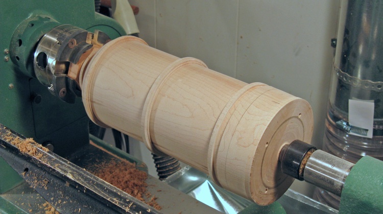
The blank, ready for turning
After this shot, the blank was then rough-turned to get to the basic shape. I left some rectangular-sectioned ridges to provide material for the rivets that went around the vessel. Forming of the top flange and hollowing out of the throat of the vessel was also done at this stage. The next photo shows the formed and sanded vessel.
Hollowing
It was about this point that it occurred to me that there was no really compelling reason why I should try to hollow out the entire vessel from the throat. That would be pretty time-consuming and would add nothing to the piece (except as Mr. Churchill would put it; blood, sweat, toil, and all too likely; tears). So instead of that, I cut the top off and hollowed it out from the large opening.
Outside shaping and hollowing done
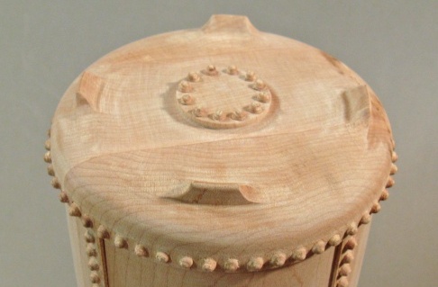
This is the hollowed vessel with the detached lid beside it. I made a shoulder on the lid that fit tightly onto the body so as to keep the alignment perfect when it was reassembled.
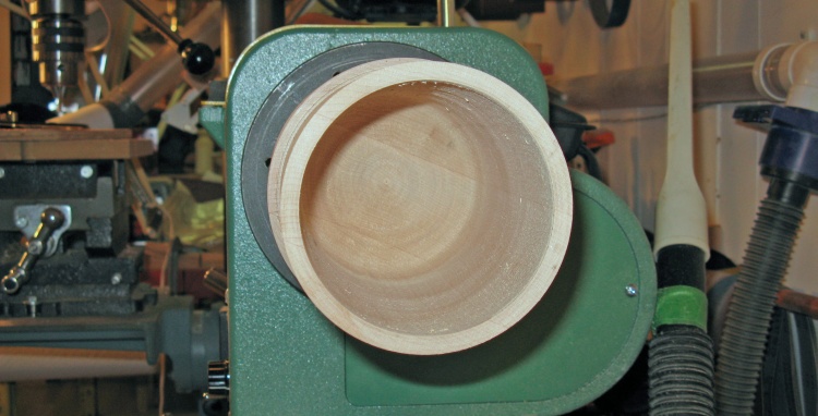
The actual hollowness
This shows the hollowed inside of the vessel. I kept the walls around 0.2" in thickness for strength. The three pieces of wood forming the body can be seen as lines between the differently-grained sections.
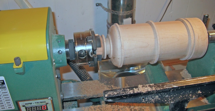
Flipped around to do the bottom
The next step was to turn the bottom. It isn't usually practical to do that kind of shaping at the faceplate end since there is usually little room to get tools in - unless there are several inches of material to cut away just to make room. Instead, I reversed the piece. To ensure it stayed centered, I turned a cylinder of the correct diameter to fit snugly into the top-side hole. With this cylinder held in an adjustable-jaw chuck, and with the top set back in place, the piece was flipped end-for-end. It was supported at the bottom with a live center in the tailstock.
Bottom ready for shaping
This shot shows the bottom before turning. The portion that will be kept extends down only to the pencil line on the outside. The top of the piece was just dry-assembled at this point, so pressure from the live center was used to squeeze the pieces together.
I wanted to have the option of putting the piece back on the lathe later if I needed to (and I did), which meant that the center of the bottom wood would need to be left intact to engage with the tailstock center. So when the bottom was shaped (including bottom "cover plate"), there was a thinner shaft left protruding from the middle of the plate to engage the center. That shaft was later cut off with a handsaw and the "cover plate" smoothed with the aid of a Dremel tool.
I wanted to have the option of putting the piece back on the lathe later if I needed to (and I did), which meant that the center of the bottom wood would need to be left intact to engage with the tailstock center. So when the bottom was shaped (including bottom "cover plate"), there was a thinner shaft left protruding from the middle of the plate to engage the center. That shaft was later cut off with a handsaw and the "cover plate" smoothed with the aid of a Dremel tool.
Rivet Forming
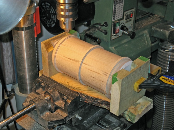
The center shaft was also useful so it could act as an axle. Rivets had to be cut around the circumference of the vessel in three rows (55 per row), which required a jig that allowed it to rotate. I built a crude jig from some old fence boards. It allowed the piece to rotate around the flange at the top, and the shaft at the bottom. With this mounted on the drill press, the piece could be rotated by hand (6.545�, give or take a degree or two) and the individual rivets cut. A round sheet of white paper can be seen on the near end of
the piece in the photo below. This was an indexing sheet with 55 radial lines, attached to the wood and allowing the piece to be rotated the desired amount between rivets.
I had considered several ways to form the rivets, but any way other than cutting them with a motorized tool simply wasn't going to be practical.
I had considered several ways to form the rivets, but any way other than cutting them with a motorized tool simply wasn't going to be practical.
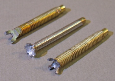
Evolution of cutting bit development
I couldn't find a suitable cutter for any plausible "rivet" shape, so one had to be made. After a couple dismal failures developmental prototypes, I ended up with a 4-flange cutter made from a largish Philips-head screw. It was softer metal than might be desired, but at least that made it easier to form and sharpen. However, by the time the cutting was done, the poor thing had one flange missing and another had been severely distorted and bent back into place.
This photo shows the evolution of the cutters, with the rightmost being the final (post-use) missing-prong one that was used.
This photo shows the evolution of the cutters, with the rightmost being the final (post-use) missing-prong one that was used.
Shaping the rivets
For the vertical sections of rivets, little strips of wood were cut, and the rivets shaped on the drill press in a similar manner as shown here. These pieces were then cleaned up by hand and glued onto the main body. The top was also glued on at the same time.
Unfortunately, not all rivets were cut cleanly. Various problems like grain direction, cutter sharpness or maybe my technique resulted in a number of broken rivet shapes. The worst of these were removed, and spare rivets cut off from another piece were glued on. This was also the technique used to add rivets to the top and bottom flanges, where it was impractical to cut them in place.
Unfortunately, not all rivets were cut cleanly. Various problems like grain direction, cutter sharpness or maybe my technique resulted in a number of broken rivet shapes. The worst of these were removed, and spare rivets cut off from another piece were glued on. This was also the technique used to add rivets to the top and bottom flanges, where it was impractical to cut them in place.
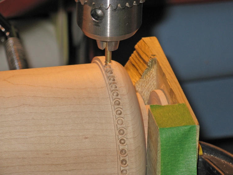
Rivet cutter close-up
This photo shows a closeup of the cutter and one ring of rivets being formed. The cutter design included a flat bottom to establish the base of the rivets. I cut down to a depth such that the base was even with the adjacent surface. The little dog-bone-shaped sections between the rivets had to be cut out by hand. I also ended up making a special little chisel to make that a bit easier to do.
Feet
Bottom detail
To make the feet, I started by forming a protruding ring of wood when the bottom was cut on the lathe. The position of the four feet on the ring were marked, and then the ring sections between the feet were carved away. The carving was done mostly with a Dremel followed by hand sanding to get to the final contour needed.
The photo to the right shows the feet after forming, and below are a couple shots of the completed vessel before the finish was applied.
The photo to the right shows the feet after forming, and below are a couple shots of the completed vessel before the finish was applied.
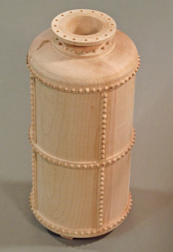
Full vessel, unvarnished
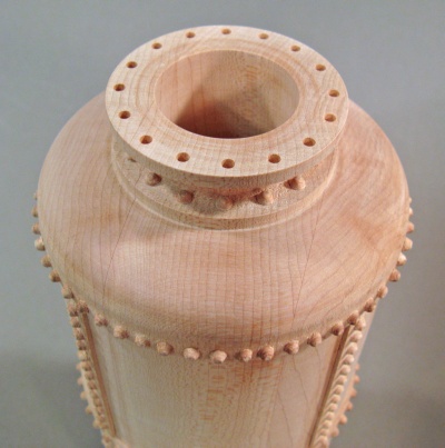
Top flange detail
Finishing
The vessel, inside and out, was dyed using an alcohol-based black aniline dye. The dye is a chemical that changes the colour of the wood and helps hide the grain. This is in contrast to a stain, which has small particles that lodge in the pores of the wood and tend to make pores and grain more visible. After dying, a couple coats of polyurethane (my favorite wipe-on stuff) was used - again inside and out - as a finish.
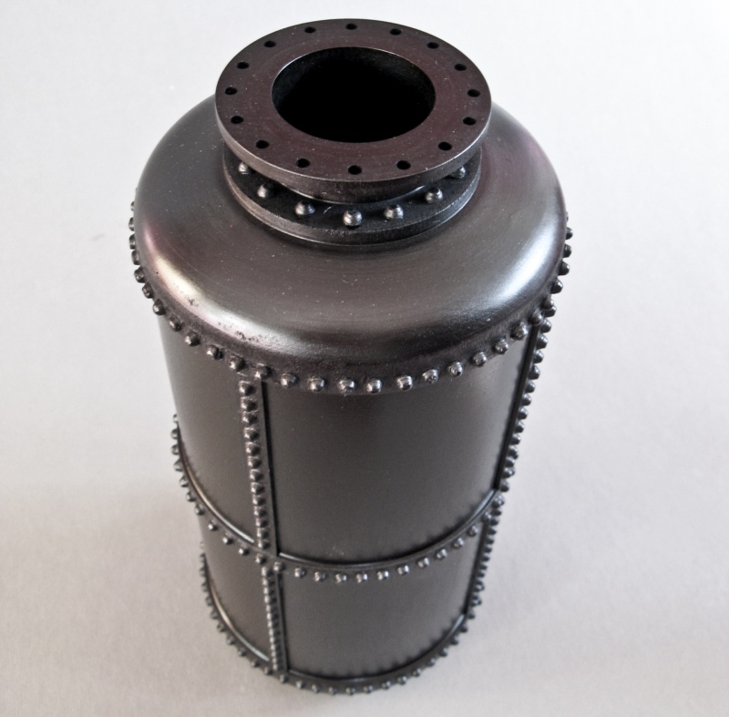
Done
You have successfully reached the bottom of this page.


