I spent an unreasonable amount of time thinking of an appropriate "theme" for the vessel into which I could incorporate the tensegrity geometry and since I failed to generate any good ideas, almost went ahead with a paisley-based vessel. Now I don't actually like paisley but the shapes unfortunately lent themselves nicely to the geometry. Fortunately I ultimately decided the geometry should be at the forefront so after switching to wood with a more-interesting grain, I went for an unadorned interlocking pattern that showcases the effect.
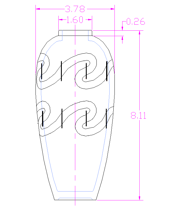
A less-than-photorealistic rendering of the vessel
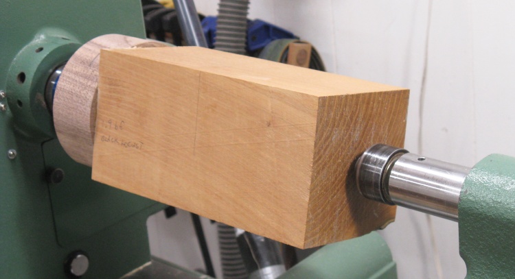
A block of Black Locust on the lathe
I had initially planned for a larger vessel but the only large piece I had was Maple. Unfortunately after it was turned I decided that the grain wasn't interesting enough so it was abandoned.
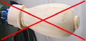
Kinda plain
My fallback was this smaller piece of Black Locust. Here I've already glued a thick disc to the bottom to accept the faceplate screws and mounted it to the lathe.
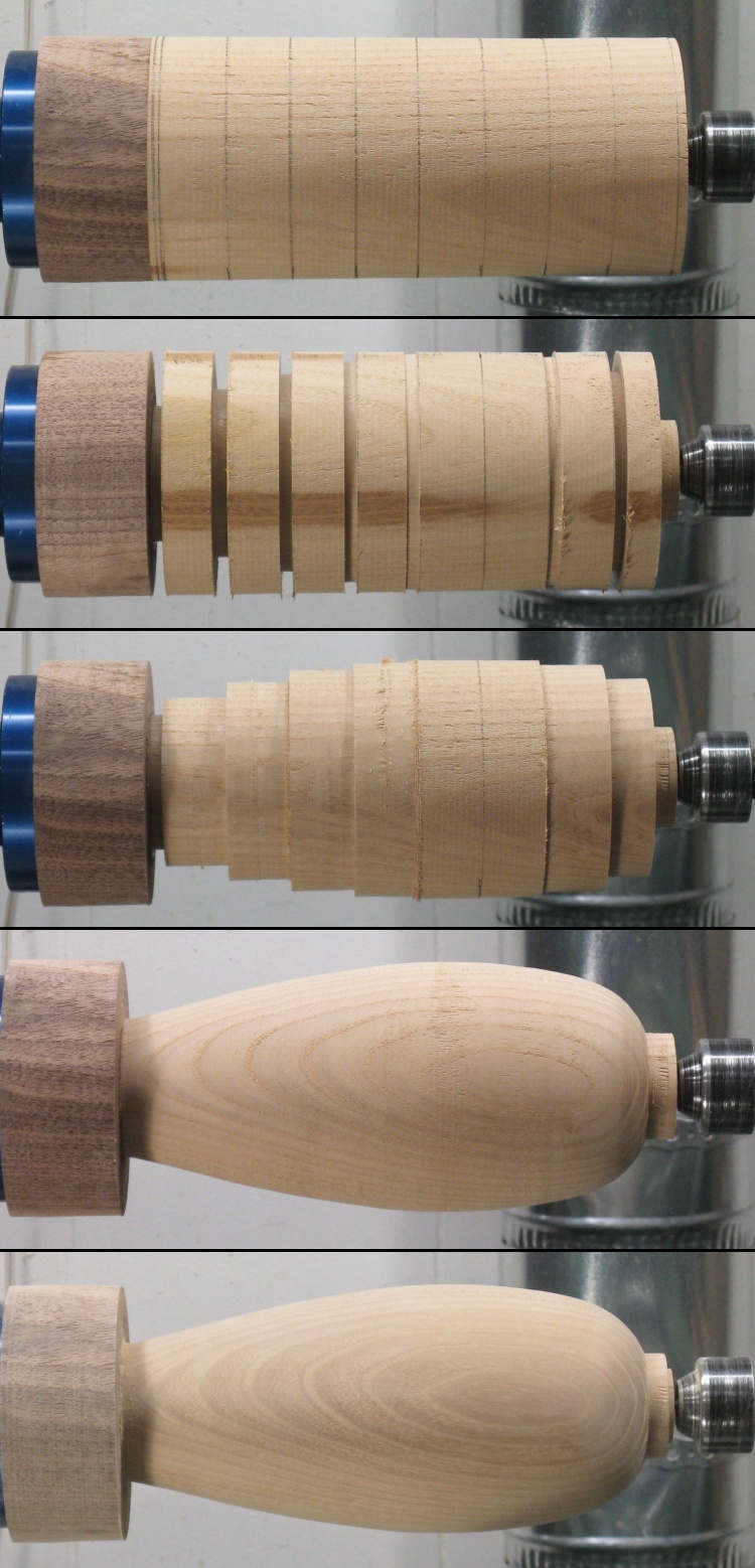
The turning composite
This turning composite summarizes the outside shaping.
I used my standard turning approach and got it done in only 5 photos.
I used my standard turning approach and got it done in only 5 photos.
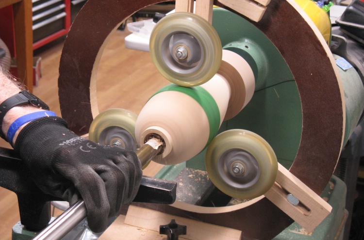
Starting on the hollowing
As usual, I used the captured turning tool for the hollowing.
I wanted a reasonable amount of strength so I left the walls at about 1/4" thick.
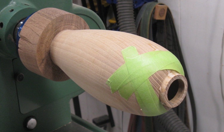
This has the plastic strip wrapped around the vessel (under the green masking tape) to prevent the wheels from indenting the sides. The vessel was a bit shy on diameter so I didn't want to risk having to reduce it even further to get rid of a wheel-caused dip.
I wanted a reasonable amount of strength so I left the walls at about 1/4" thick.
This has the plastic strip wrapped around the vessel (under the green masking tape) to prevent the wheels from indenting the sides. The vessel was a bit shy on diameter so I didn't want to risk having to reduce it even further to get rid of a wheel-caused dip.
Gluing some cracks
I'm not sure if the wood was already cracked or whether my turning did it (yah, probably my turning) but I ended up gluing two or three cracks and taping the walls together while it dried.
Smoothing the bottom
The bottom was done the usual way;
- Make a jam chuck to fit the top
- Flip the vessel around
- Cut away the bottom disc and form a foot
and then finally smooth the bottom as shown in this photo.
- Make a jam chuck to fit the top
- Flip the vessel around
- Cut away the bottom disc and form a foot
and then finally smooth the bottom as shown in this photo.
~Aside~
Halloween occurred as I was working on these pages and as usual we set up the jack-o-lantern and handed out candy. My spouse noted what a questionable "investment" Halloween turns out to be. As a kid it's great but you collect candy from say 3 years old if your parents are gung-ho to maybe 10 or 12 (or even 14 if you are short and/or cute). That's something like 10 years of candy as a kid. And then as an adult you hand out candy from when you get a house until your ungrateful kids move you into a nursing home. We've been handing out candy for 36 years already so that 10-year payoff as a kid isn't looking too great.
This is like borrowing years of collecting candy as a kid and accumulating interest on it. Then the principle and interest gets paid back as a home-owning adult. Clearly what we need here is some math; Let's assume the gung-ho parents so you start "borrowing" candy at 3 and being a short person, you collect candy for 10 years. Then you buy a house at 28 and hand candy out for 40 years. I'm going to say that's a (28-3=) 25 year term where you pay (40/10=) 4x what you borrowed (in years anyway). That represents a Candy Time interest rate of 5.7%. Actually that doesn't sound too unreasonable although on most loans you start paying back the principal right away instead of waiting 25 years. Of course you could just avoid handing out candy but come on - there's an intergenerational social contract here.
Anyway, when the doorbell stopped ringing it was back into the basement;
Marking nice vertical section lines
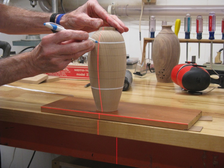
With the vessel turning done, it was time to mark it with five evenly spaced lines to guide the drawing-on of the pattern.
Needing a vertical line gave me the excuse to pull out the laser level. I had marked evenly-spaced sections on the lower tape and used the laser to guide the marking of the top tape line. Then I used a flexible straightedge to go between the top and bottom marks and drew in pencil lines.
I actually needed a total of 10 lines but left the five in-between lines off since I thought they could confuse things a bit.
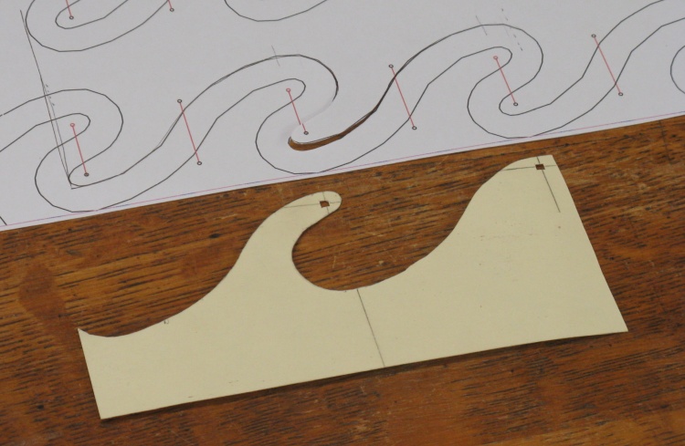
A pattern to transfer shape to the vessel
The finished vessel would have a pair of wavy slots like those on the paper plan. To transfer the shape to the vessel I cut out a pattern from thin cardboard for a small section.
This shape is repeated around the vessel and the pattern is traced right-side-up to draw the bottom of the slot and upside-down for the top.
This shape is repeated around the vessel and the pattern is traced right-side-up to draw the bottom of the slot and upside-down for the top.
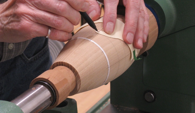
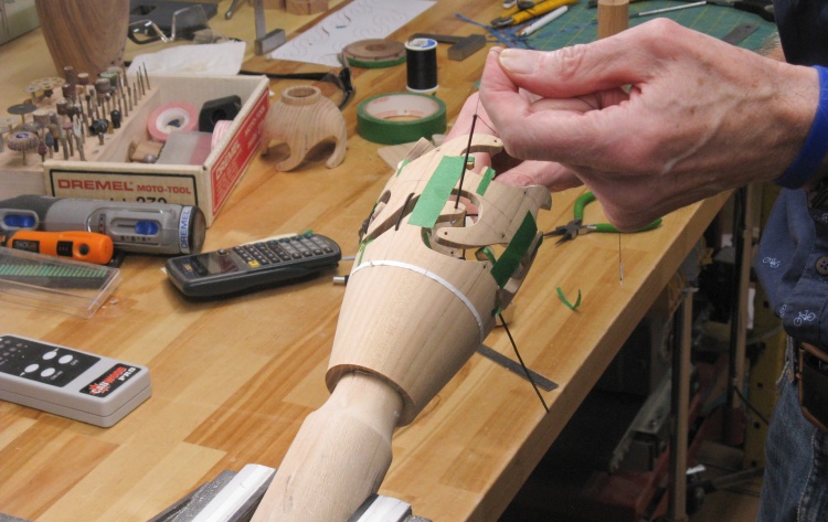
Tracing the shapes with a pattern
A few lines were drawn around the vessel at appropriate spots and the crossing of the vertical lines indicated the placement of the holes.
I positioned the cardboard pattern at each hole location and traced the outline to get the proper shape.
Now the "do it precisely" engineering part of my brain pointed out that technically the pattern should be scaled and distorted appropriately to exactly correspond to the reducing diameter of the vessel. But I have no small amount of experience ignoring good advice so I just used the same pattern all over and "fixed" the connection between each section. Much easier.
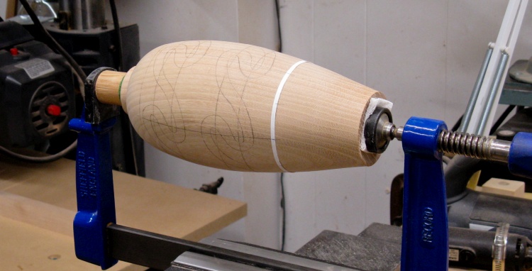
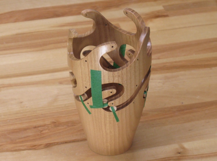
Marked and mounted for cutting
Once both slots were marked, the Area of Operations was moved to the bench. A tight-fitting dowel was inserted which let me clamp the vessel bottom to hold things in place without stressing the vessel walls (which were shortly going to be chopped apart).
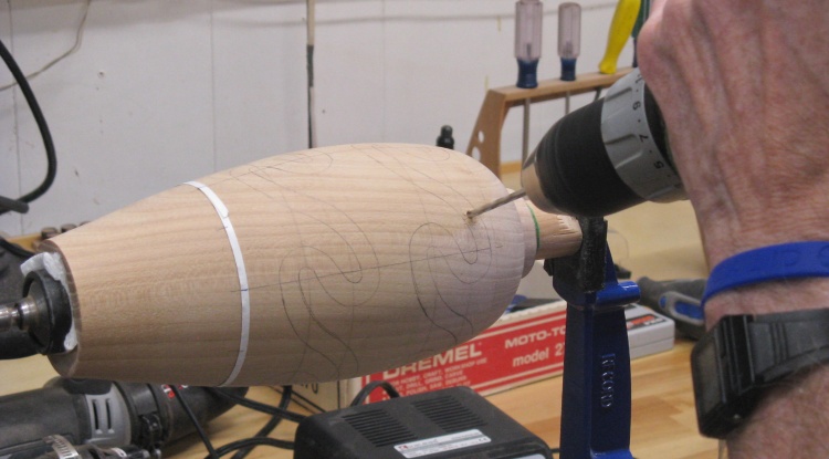
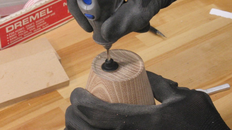
Step 1: drill starting holes
To proceed with the chopping I first drilled pilot holes.
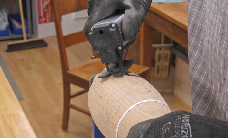
Step 2: cut out the thin sections
...and then used my mini jig saw to cut just inside the lines.
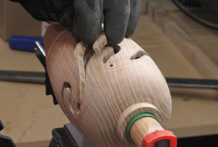
A piece of a thin section coming out
I removed short sections as I proceeded.
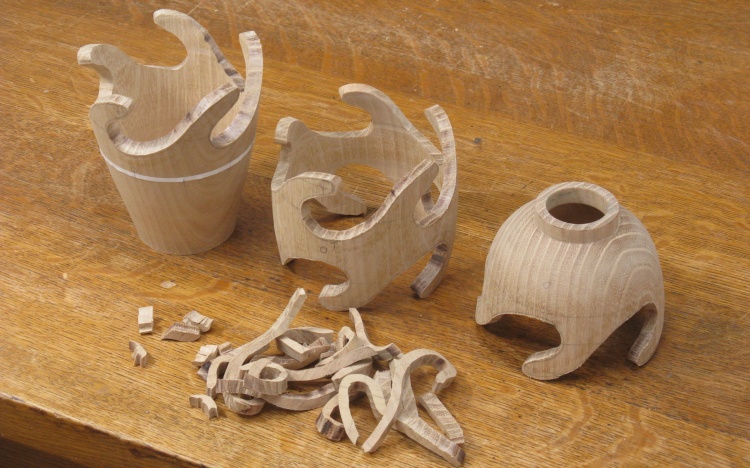
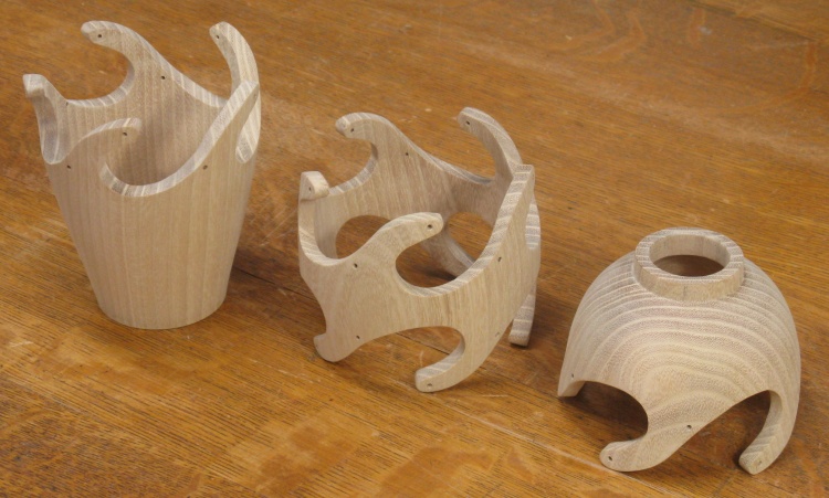
The resulting three pieces and the leftover bits
This shows the three pieces after the two slots were cut out (with the cut-out pieces artistically piled in the foreground).
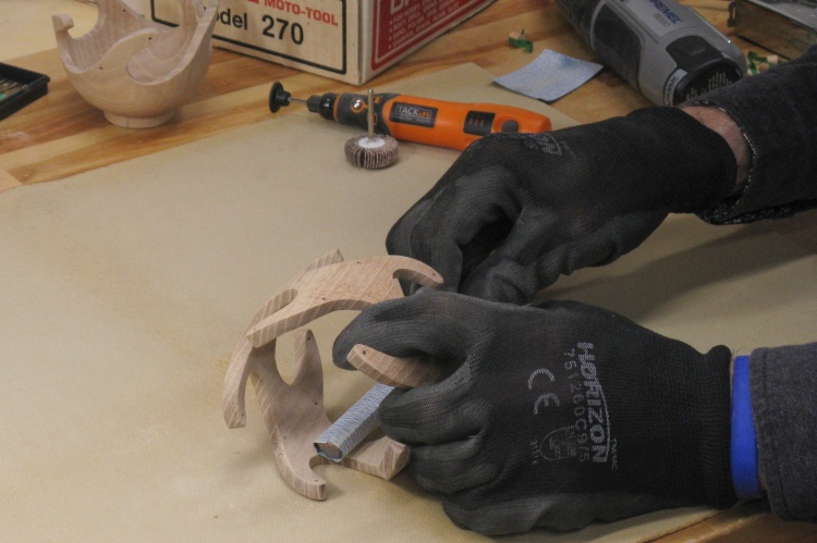
Sanding the edges smooth
Next was sanding down the rather inconsistently-cut edges. I wanted to hold the pieces consistently horizontal for the correct sanding angle (which I found difficult to do by hand) so I added round bases to each piece. The base would rest on a supplemental table clamped to the drill press.
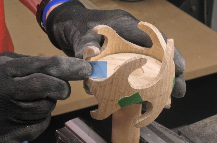
And then hand sanding, of course
Once all three pieces had the edges sanded with coarse and then fine sanding drums, I switched to hand sanding to remove any remaining scratch marks and round off sharp corners.
In this photo the middle piece is getting some attention with 220 grit.
In this photo the middle piece is getting some attention with 220 grit.
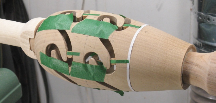
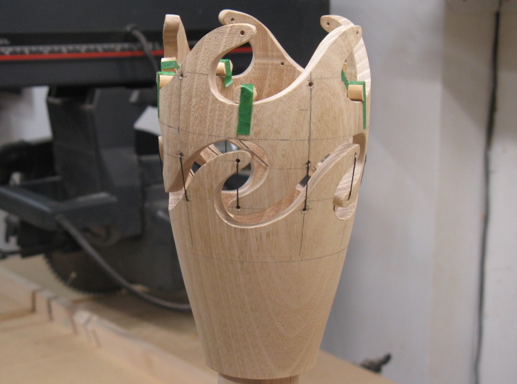
Reassembled vessel to mark hole locations
So back a dozen or so photos ago I explained that I needed 10 vertical lines but drew only 5 since I didn't want to "confuse" things. But now I need those other 5 lines and the vessel is in three pieces. Oops.
Trying to measure the correct positions of the lines on each piece didn't go well so I bit the bullet and reassembled the whole thing. I made some dowel spacers that held the gaps open the correct distance, aligned the pieces and taped them together.
Trying to measure the correct positions of the lines on each piece didn't go well so I bit the bullet and reassembled the whole thing. I made some dowel spacers that held the gaps open the correct distance, aligned the pieces and taped them together.
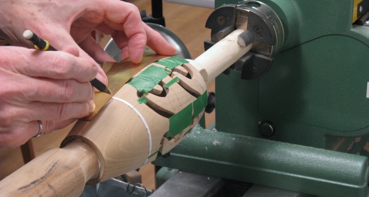
Drawing longitude lines for holes
Then I could draw those missing 5 lines, needed to indicate the positions of the alternate set of thread holes.
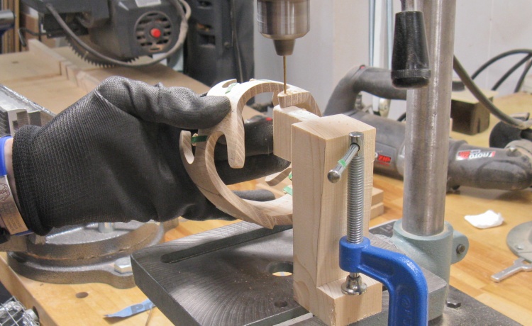
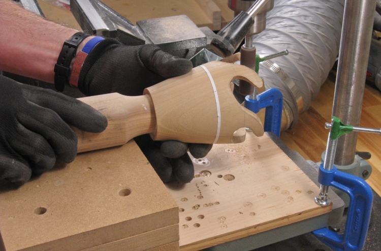
Drilling the holes with custom jig
Then I could start drilling holes for the threads.
Given the odd geometry of the pieces, I whipped up a 2x4-based piece to support and back the pieces as they were drilled. I used a 1/16" drill which was just slightly larger than the diameter of the elastic thread.
Given the odd geometry of the pieces, I whipped up a 2x4-based piece to support and back the pieces as they were drilled. I used a 1/16" drill which was just slightly larger than the diameter of the elastic thread.
Sewing two pieces together to make sure it all works
I thought I'd better try at least one threaded-together joint to make sure everything worked Like I was planning.
I tied a thin leader to the elastic thread and sewed the two lower pieces together.
I tied a thin leader to the elastic thread and sewed the two lower pieces together.

The lower two pieces together
When done, it looked pretty much as expected.
Checking with regular thread
I wasn't sure the elastic thread was necessary so I also tried the two pieces with a standard thick thread.
It worked, but any loss in thread tension would have things sagging. Looks like elastic is the way to go.
It worked, but any loss in thread tension would have things sagging. Looks like elastic is the way to go.
Sanding the insides
After pulling off the tape, out came the eraser and rubbed off the pencil marks. Then out came the sandpaper to do finish sanding on both the inside and outside.
All the woodworking done on these now
That was it for the woodworking. These three are ready for some finish.
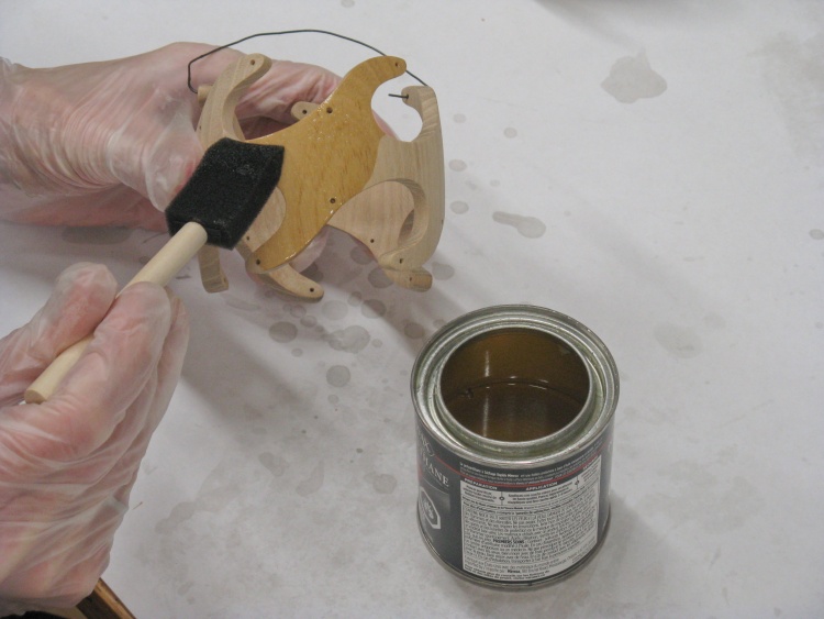
Adding the first coat of finish
I added some wire loops through the thread holes for handling and started on the first coat of polyurethane varnish.
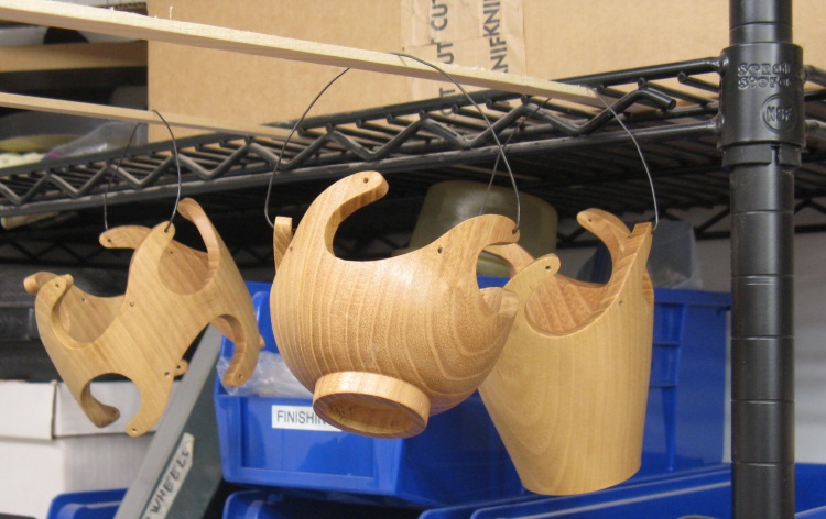
Varnish drying
The pieces were hung up close to the exhaust fan to dry.
They received three coats of varnish with the usual roughening-up with steel wool between coats.
They received three coats of varnish with the usual roughening-up with steel wool between coats.
Taped together and ready for thread
After the last coat of varnish was dry the bottom and middle sections were assembled with spacers and tape.
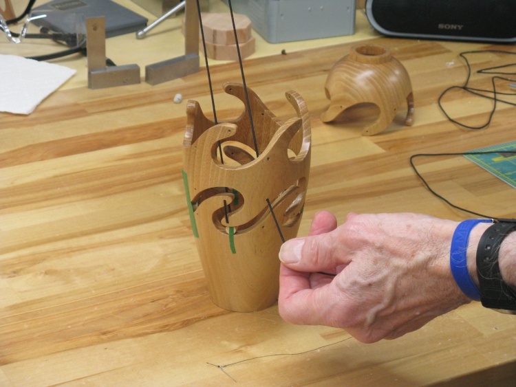
Pulling through a thread
And then the two pieces were sewn together with the elastic thread.
I used a single piece to do all the holes between the two pieces, mostly to make the process easier. It meant I needed to anchor only 2 thread ends rather than 20, plus it made it possible to tweak thread tension after assembly to make sure the gaps were consistent.
I used a single piece to do all the holes between the two pieces, mostly to make the process easier. It meant I needed to anchor only 2 thread ends rather than 20, plus it made it possible to tweak thread tension after assembly to make sure the gaps were consistent.
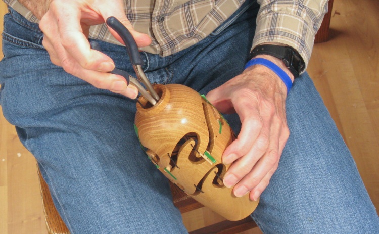
Using long-nosed pliers on the top section
The top piece was attached the same way although I needed the help of pliers to reach inside and aid the feeding-through of the stiff leader I had attached to the thread.
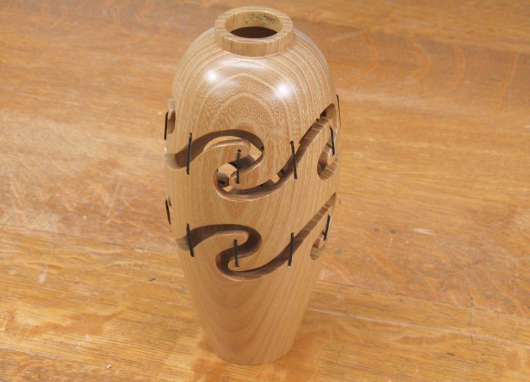
Complete
And that was it.
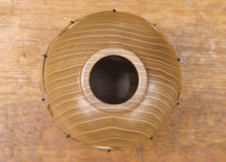
The top view
A top-down view.
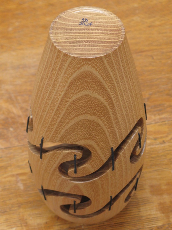
...and the bottom
And a shot of the bottom.
The Support Geometry
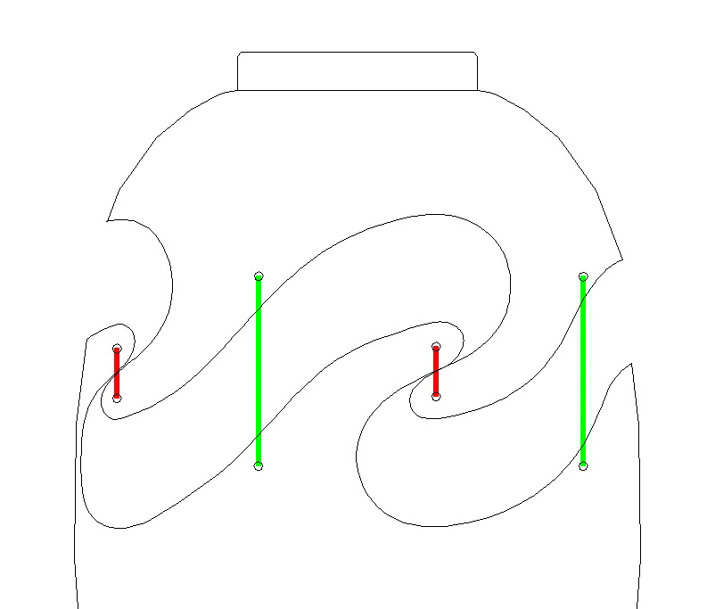
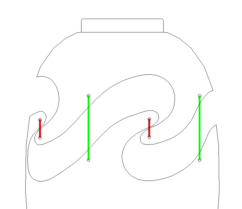


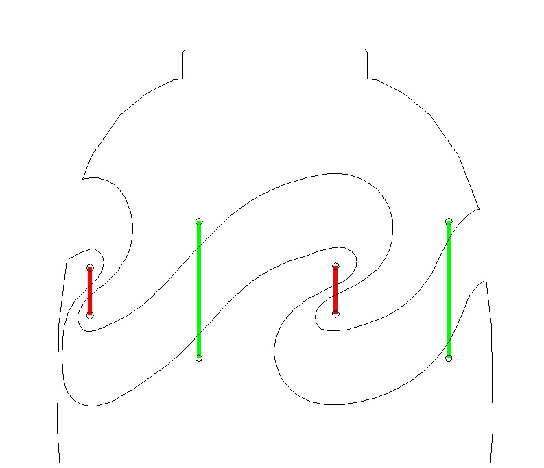

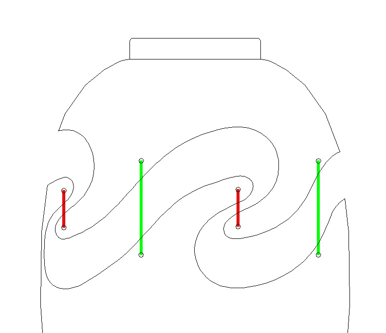

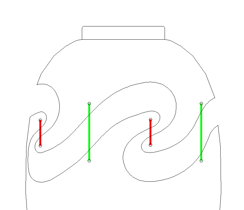
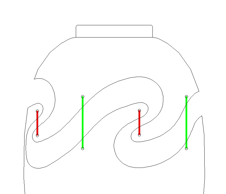

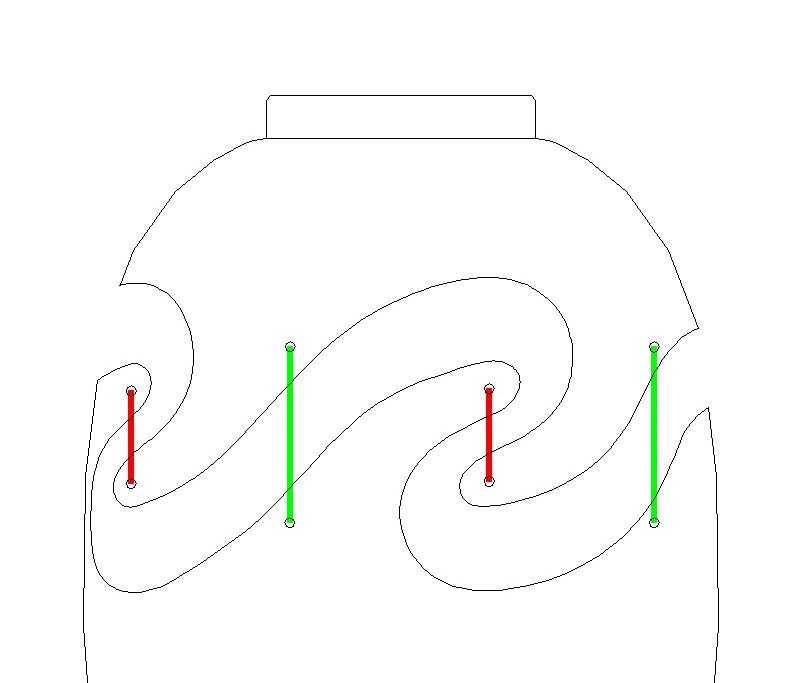
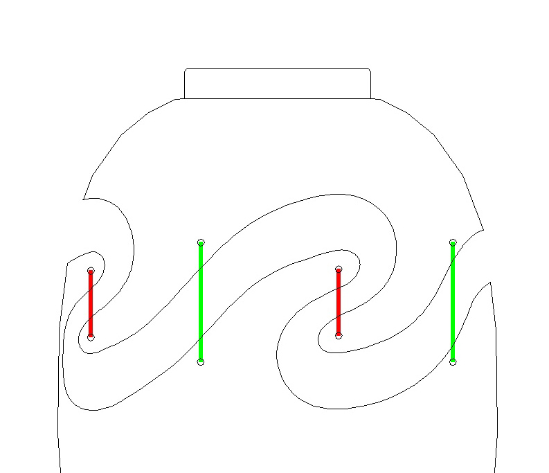
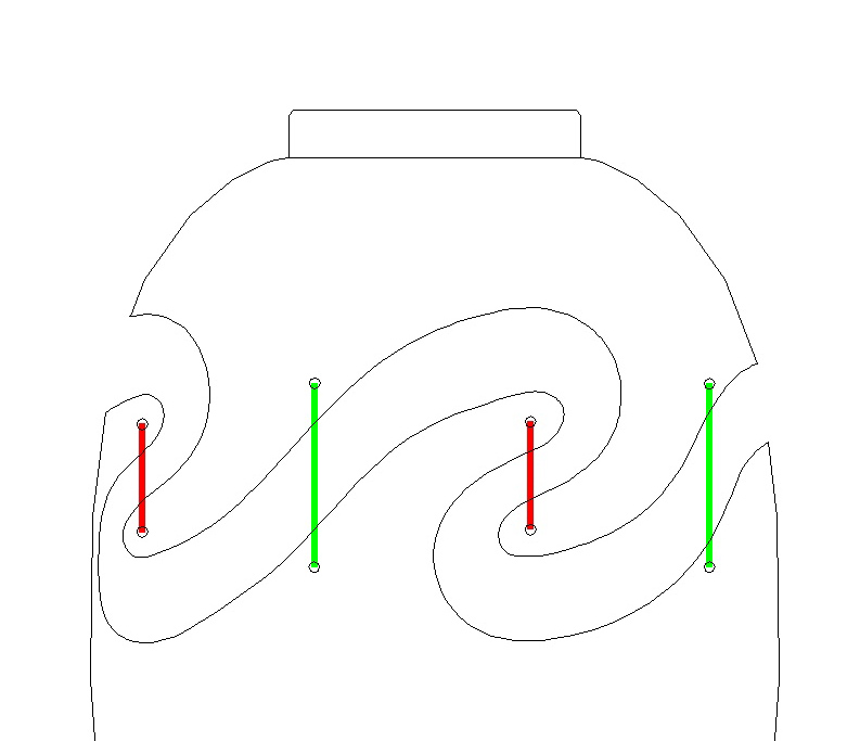

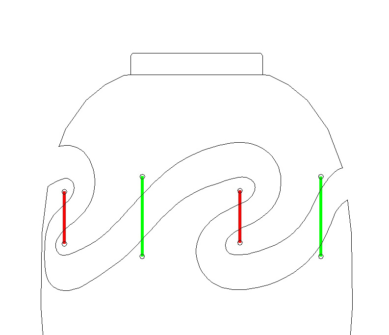
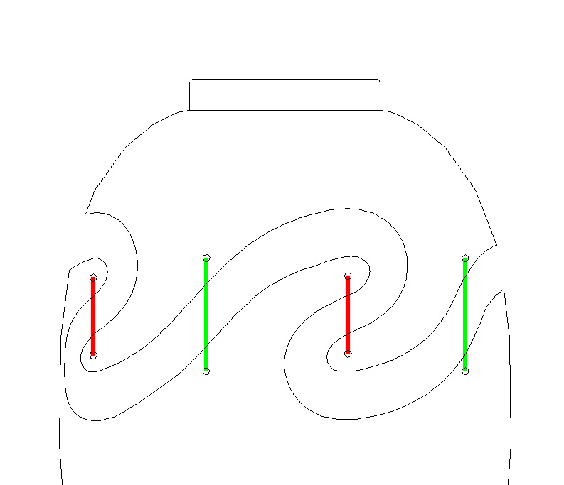

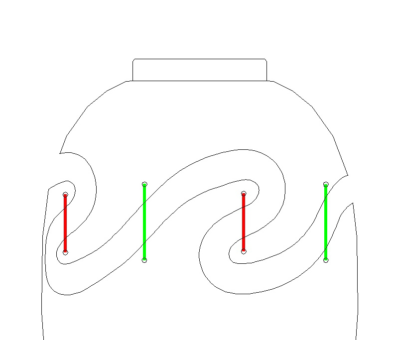
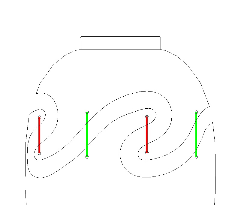

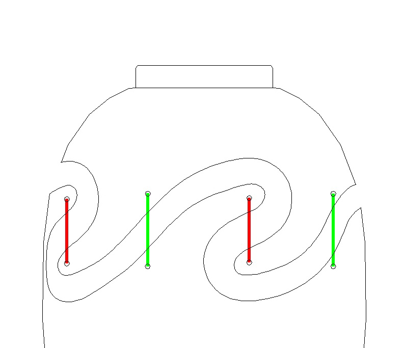
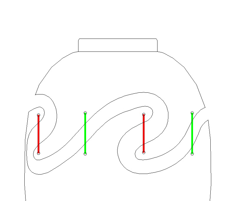

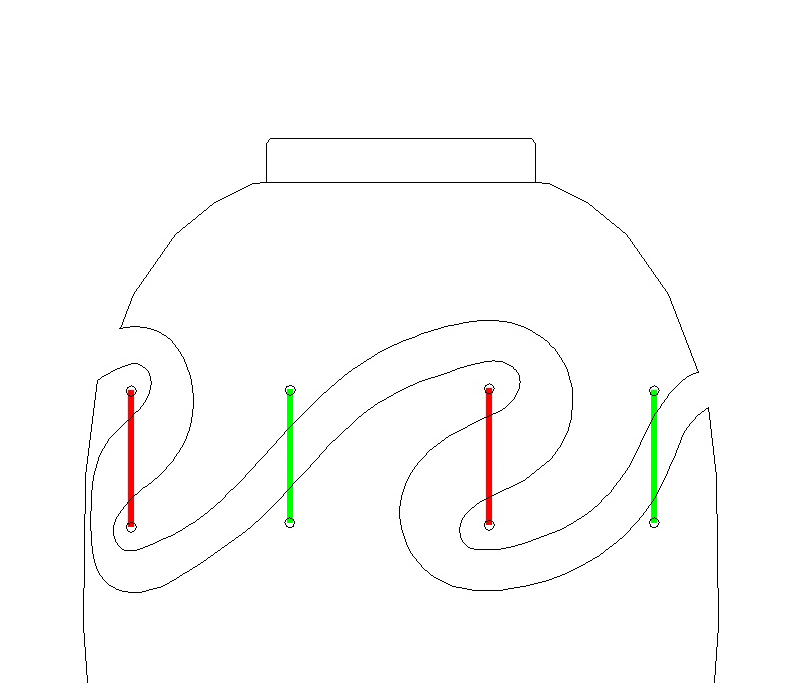

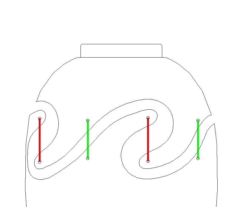
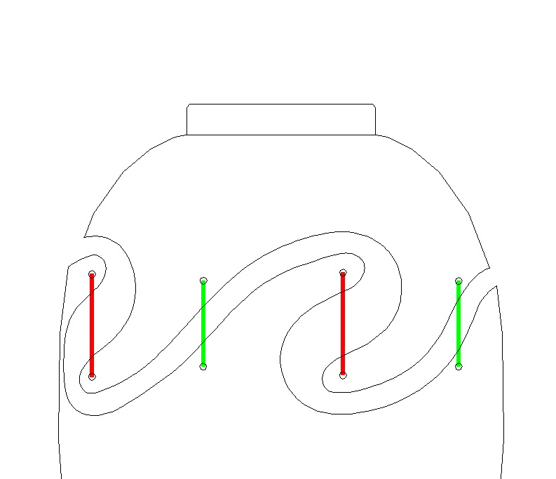
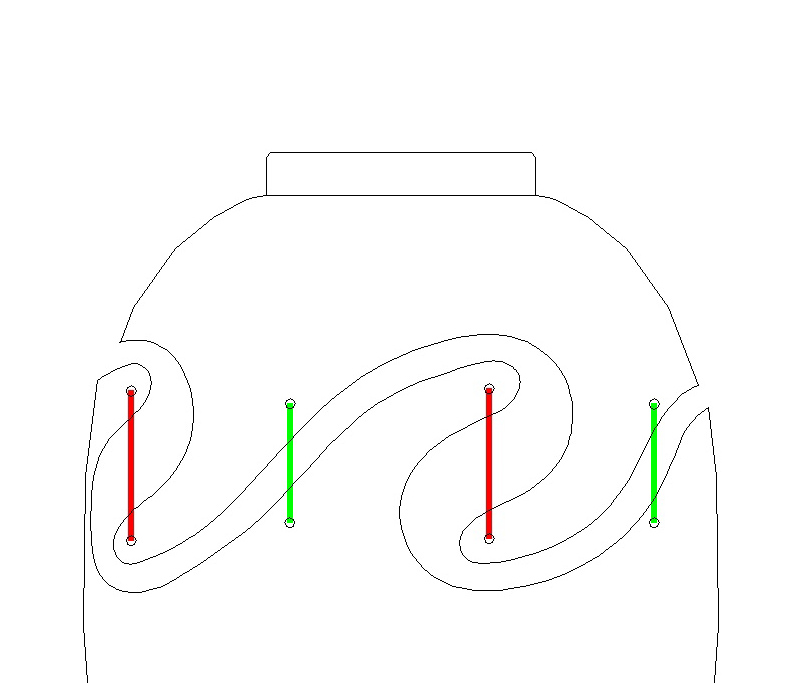
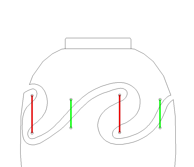

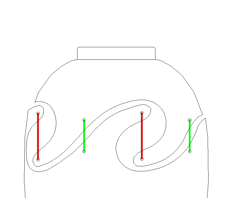


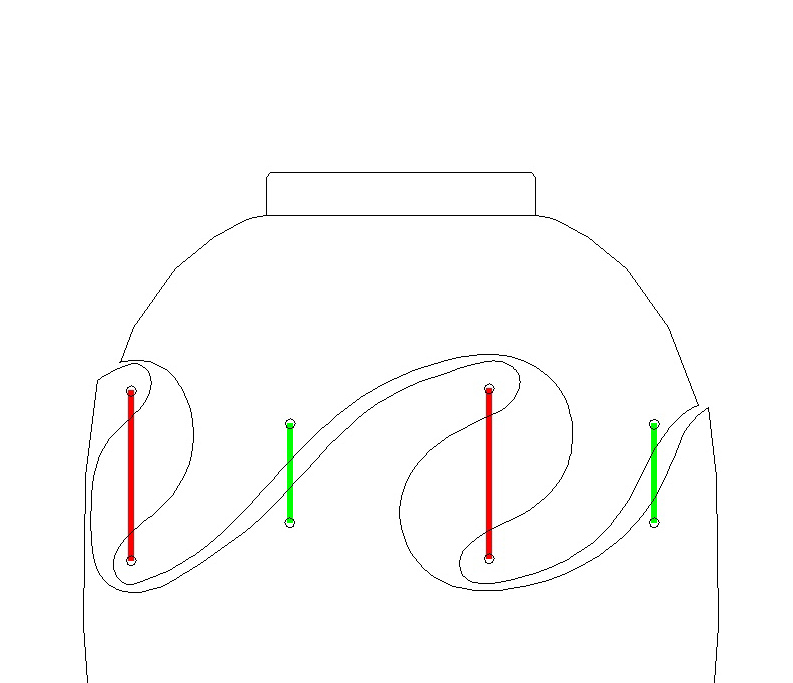
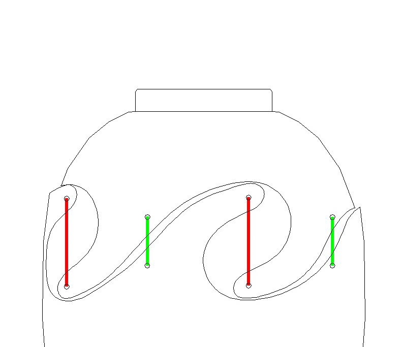
The arrows below will raise and lower the top section and you can see how the green or red threads stretch in response.
When moving things off-center in either direction one set of threads lengthen (so more tension) while the other set shortens (so less tension). The gap normally sits at the default width where there is even tension on the threads.
When moving things off-center in either direction one set of threads lengthen (so more tension) while the other set shortens (so less tension). The gap normally sits at the default width where there is even tension on the threads.


