Many years ago I had started to make a small rectangular clock body using the slice-and-fill technique, but it ended up not being needed and it didn't get too far past the first "slice" stage. However I liked the concept of having intersecting lines through an object and was reminded recently when I noticed a turned wooden pen using this technique in a Lee Valley Tool store display. I was considering designs for a new turned object at the time, so this technique looked like a good fit.
Once again I've used maple and walnut since I like the contrast that combination provides, besides which I happened to have suitable pieces lying around. Now of course this would be another "Maple-Walnut" object but since it is better defined by the trefoil shape of the intersecting surfaces, I used that as the descriptor.
Once again I've used maple and walnut since I like the contrast that combination provides, besides which I happened to have suitable pieces lying around. Now of course this would be another "Maple-Walnut" object but since it is better defined by the trefoil shape of the intersecting surfaces, I used that as the descriptor.
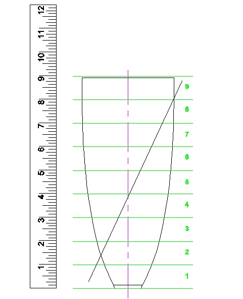
The not-especially-detailed plan
Starting Blank
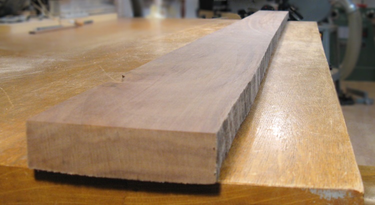
A nice 4-inch-wide walnut plank
This is an almost-4-inch wide plank that would be enough for the whole vessel. It's knot- and crack-free which is good since I needed pretty much all of it.
I actually tweaked the size of the vessel to ensure it could be made from this single board.
I actually tweaked the size of the vessel to ensure it could be made from this single board.
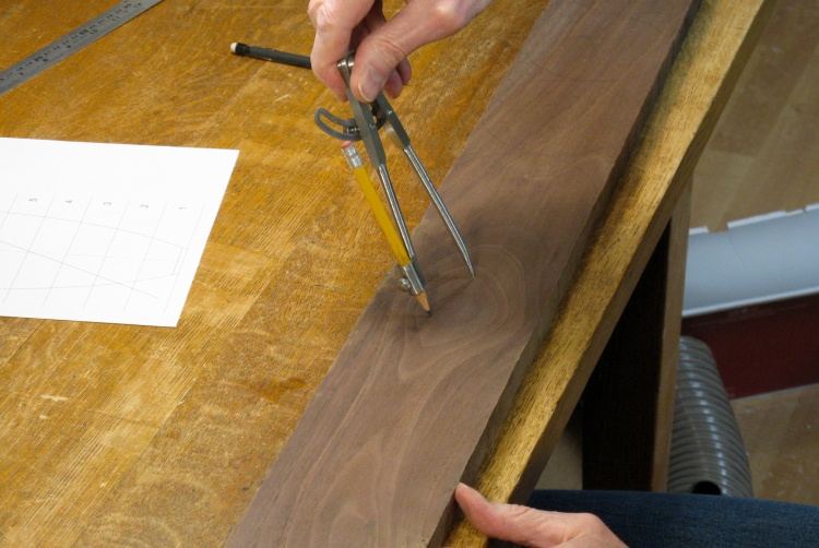
Marking out the layers
After a bit of thickness planing done mostly to clean up the faces, I drew circles on it as a guide to cutting out the 9 layers that would be needed.
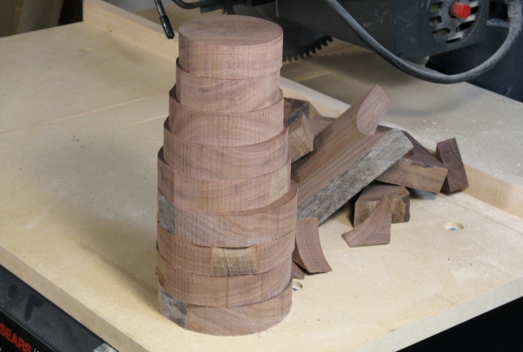
Flat plank transformed into circular stack using Bandsaw Magic
I used a bandsaw with a narrow blade to cut out the discs and in fairly short order the plank was cut into the stack seen here.
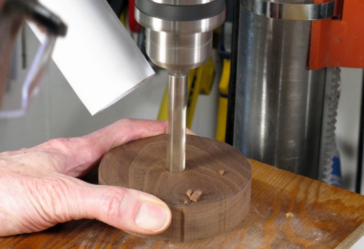
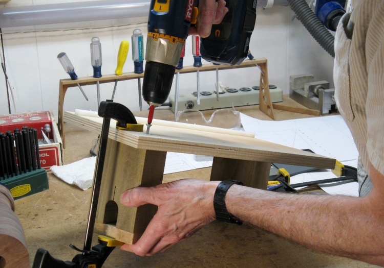
Drilling a center guide hole
My plan for keeping pieces aligned involved using a half-inch steel rod through the center of all the pieces.
Here one of the layers is getting a 1/2" hole drilled in the center to accommodate the rod.
Here one of the layers is getting a 1/2" hole drilled in the center to accommodate the rod.
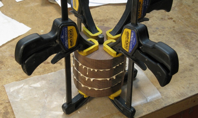
The top half of the vessel with a generous helping of glue
The layer lamination was done in two stages with the four top layers being glued together first. A short metal rod used for alignment is visible between the clamps.
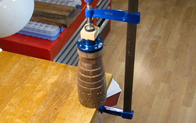
The full stack getting glued
This photo shows the full vessel being glued. In addition to the nine vessel layers, at the top of the stack is an extra layer for faceplate attachment topped by the blue aluminum faceplate itself.
Rather imperfectly centered guide hole
The vessel was spun up on the lathe and I marked a circle on the end.
Evidently the guide hole at the top managed to wander off-center while I was preoccupied with drilling, clamping and gluing.
I needed a guide hole which was centered, so that was gonna need to be fixed.
Evidently the guide hole at the top managed to wander off-center while I was preoccupied with drilling, clamping and gluing.
I needed a guide hole which was centered, so that was gonna need to be fixed.
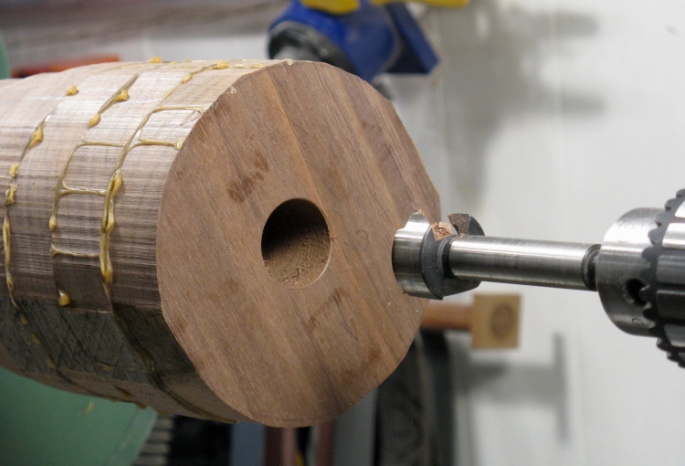
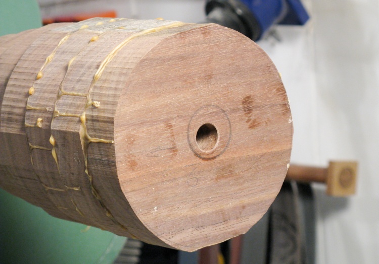
New and Improved guide hole right in the center
My solution was just to drill a larger centered hole that would be the new guide. This hole only went 3" deep since it just needed to support the end while the vessel was rotated in the jig.
Getting rid of the corners
Before starting the next stage I wanted the piece to be approximately the correct shape but just a bit larger than the final size.
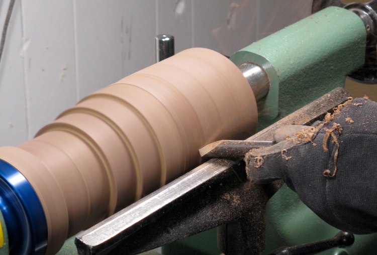
Outside has been roughly shaped
I stopped shaping when the top half was pretty close to the final size ('cause there wasn't much extra there) but I left the bottom half larger to provide some extra strength.
Slice & Fill
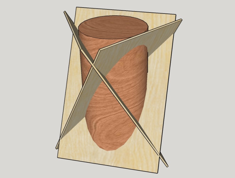
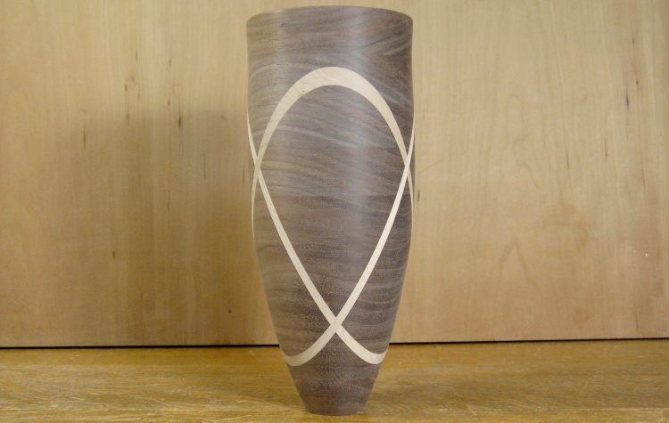
The general "intersecting planes" visualization
This diagram shows how the three maple "planes" will go through the vessel.
The planes are tilted 25° from the vertical and there are three of them spaced equally around the vessel (at 120° angles for those struggling to remember long-forgotten high school geometry).
My vessel would look like this one if I didn't bother to trim off the maple.
The planes are tilted 25° from the vertical and there are three of them spaced equally around the vessel (at 120° angles for those struggling to remember long-forgotten high school geometry).
My vessel would look like this one if I didn't bother to trim off the maple.
Making up a jig for sawing the piece
I made a jig to hold the piece for cutting which ensured that the wood was level and at the correct angle. Mounts at the ends held the faceplate and a 1" shaft, and they could be clamped when things were in position.
The jig was originally made with the white plastic piece at the far side that fit into the bandsaw mitre slot to guide the jig straight.
The jig was originally made with the white plastic piece at the far side that fit into the bandsaw mitre slot to guide the jig straight.
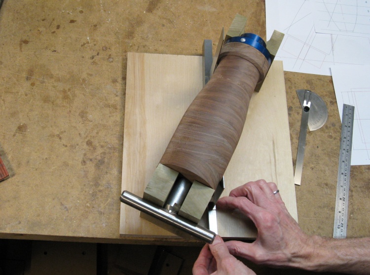
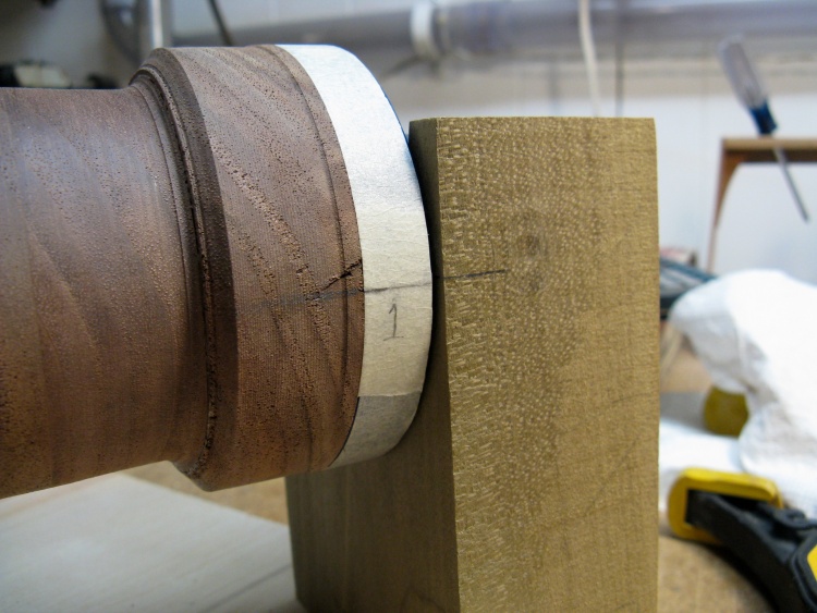
Checking the cut line with the piece mounted in the jig
This photo shows me checking the location of the cut line relative to the wood. The cut is planned to go between the blades of the two steel squares sitting on the plywood base.
I needed a 1"-diameter shaft for the top, so I just used a tool rest from the lathe since it fit conveniently. That can be seen at the top of the vessel (which is to say, at the bottom of the photo).
I needed a 1"-diameter shaft for the top, so I just used a tool rest from the lathe since it fit conveniently. That can be seen at the top of the vessel (which is to say, at the bottom of the photo).
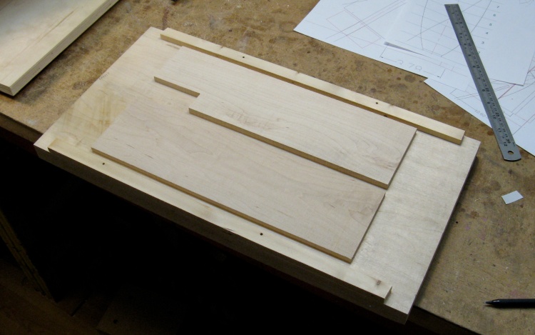
A couple of as-yet-too-thick maple pieces on the router sled
And now a brief tangent where the maple insert pieces are made; I figured they should be ready to go before I started cutting.
Here a couple pieces of maple are taped down to the big maple plank that acts as a planer sled. The sled helps eliminate snipe and makes it easier to plane thin pieces that may be under the planer's minimum thickness setting of about 1/8".
Here a couple pieces of maple are taped down to the big maple plank that acts as a planer sled. The sled helps eliminate snipe and makes it easier to plane thin pieces that may be under the planer's minimum thickness setting of about 1/8".
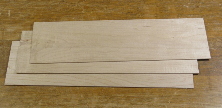
The three maple pieces ready to go
A few passes through the planer and some trimming resulted in the three maple "plane" pieces shown here.
These pieces are actually only 0.085" thick since I originally expected a thinner cut than what I ended up with. I later made three thicker pieces of 0.170" after finalizing the cut width. There's no photo of those but take my word for it that they look pretty much the same, just twice as thick.
These pieces are actually only 0.085" thick since I originally expected a thinner cut than what I ended up with. I later made three thicker pieces of 0.170" after finalizing the cut width. There's no photo of those but take my word for it that they look pretty much the same, just twice as thick.
Rotational indexing between the piece and jig; Cut #1 coming up
OK - Back to the vessel; Here the circumference has been marked in three places so the vessel can be accurately rotated between slices.
Mounted, supported and clamped in place
The vessel has been set to rotation #1, some supports added underneath and the ends clamped to hold everything solidly in place for the cutting operation.

Using bandsaw (unsuccessfully) for first cut
I had hoped to be able to use the bandsaw for the slicing but as I kind of suspected, it was not accurate enough. A tall cut like this one leaves the blade fairly unconstrained so sometimes it works fine but other times the cut wanders due to grain or sharpness or whatever whim enters its little bandsaw-blade mind.
It was evident that the blade was in fact wandering off my desired cut line so I didn't get much futher than this shot (about 2" of cut maybe) before I stopped the cut to avoid ruining the vessel.
So that raised the question: How am I going to make this cut? And now it needed to be wide enough to remove the wandering bandsaw blade cut too.
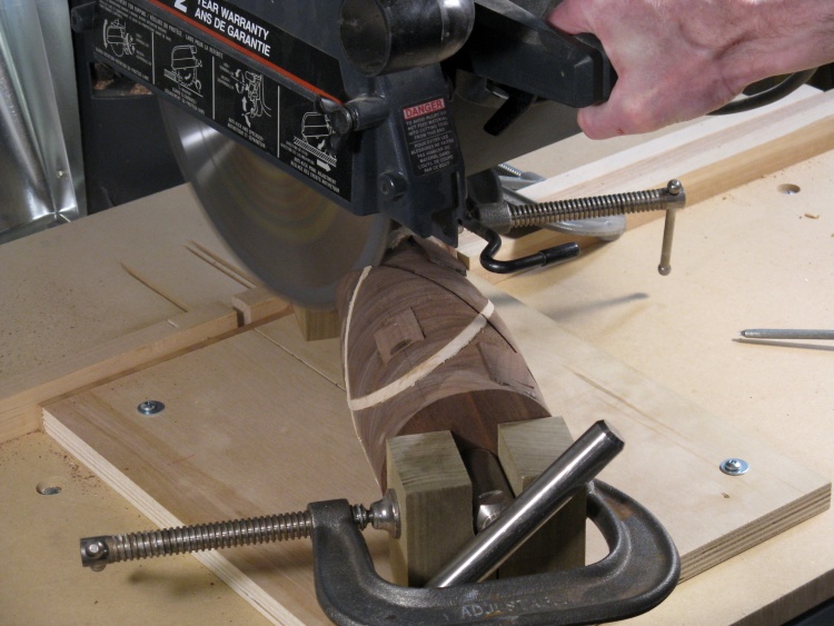
he cut piece after using a sliding mitre saw
I had needed to make a tall straight cut for another project a few years ago, and I was able to do it using a sliding mitre saw owned by a buddy of mine (yes, the same saw I borrowed for the shed).
So I called him up and headed over there (Thanks Gary!). We were able to just barely fit this into the saw but only after removing the dust collector and disabling the blade guard retractor. Some careful positioning and clamping, and it was ready to go.
I got a face and shirt full of sawdust but on the good side it made a pretty nice cut which was wide enough at 0.17" to completely erase the bandsaw cut. This photo shows the result when I got it back home.
Clamping ramps glued on
Once the maple was in place and glued, the assembly would need to be clamped. Just clamping the vessel from the sides would generate lots of force pushing the pieces along the slope of the cut. To prevent that, I glued on some little clamping ramps so the clamps would be squeezing at right angles to the cut.
Easing the center portion for better fit
I was a bit concerned that any flatness variations of the face inside the vessel might prevent a tight joint around the edges. The vessel was going to be hollowed so it wasn't important that there be a nice tight joint in the inner part so I just ground away the center portions so make sure there was clearance.
I also wanted to touch up the faces on the belt sander since they weren't quite as flat as I wanted. Having the middle section removed made that easier to do since less sanding was required.
I also wanted to touch up the faces on the belt sander since they weren't quite as flat as I wanted. Having the middle section removed made that easier to do since less sanding was required.
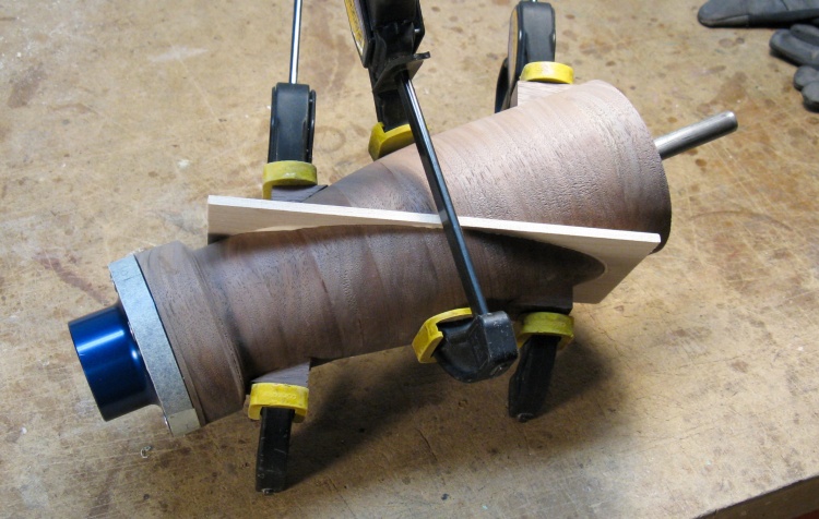
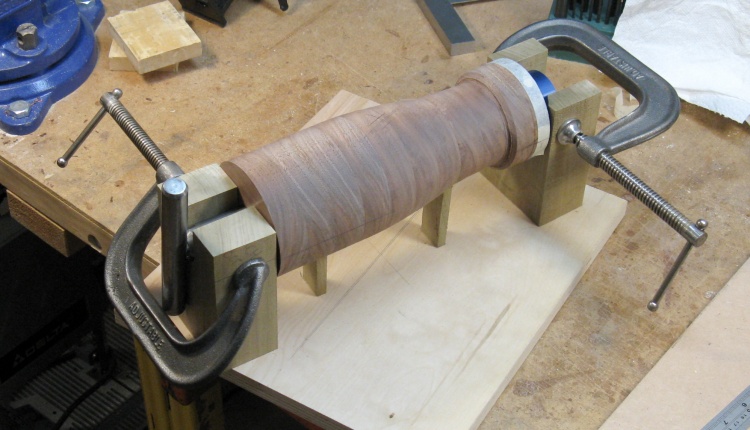
And finally clamping in the first filler piece
After cutting an oblong hole in the maple piece for the 1/2" shaft to go through, the vessel was assembled with the maple in place and all faces glued.
The 1/2" steel rod visible on the right was inserted through the three pieces and holds them in proper alignment. The two main clamps are on their ramps near the ends and a third was added near the center to help eliminate any gaps.
The 1/2" steel rod visible on the right was inserted through the three pieces and holds them in proper alignment. The two main clamps are on their ramps near the ends and a third was added near the center to help eliminate any gaps.

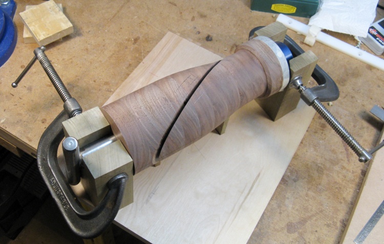
Reassembled piece after trimming off ramps and excess maple
After the glue had dried, most of the protruding parts of the ramps and maple were cut off with the bandsaw. The remaining maple protrusions were sanded off with the belt sander just so they didn't get in the way.
So that was the first of three slice & fill operations done; just need to do that twice more.
So that was the first of three slice & fill operations done; just need to do that twice more.
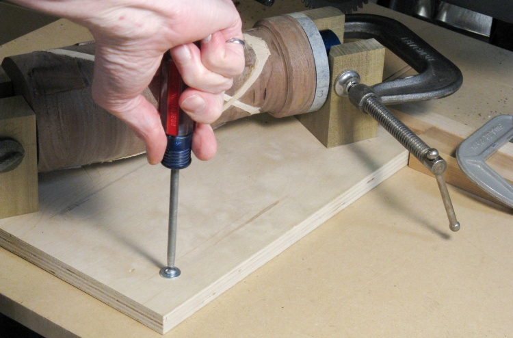
Positioning jig for cut #3
The second and third slice & fill operations used a slightly different technique than the first with the photos below reflecting the third operation.
I had originally hoped to use the radial arm saw to make the cuts since it should be very smooth and consistent, but the size of the motor limited the depth of the cut to a bit over 3" (despite the 10" blade diameter). Since the vessel was almost 4" diameter, that meant the saw would cut only partway through.
However I saw good results using the belt sander to smooth the faces, so the plan I adopted was to cut partway through, then cut the rest of the way with the bandsaw (since its kerf is much narrower) and sand off the excess.
This photo shows the jig being screwed down to the radial arm saw table to hold it in place for the sawing operation.
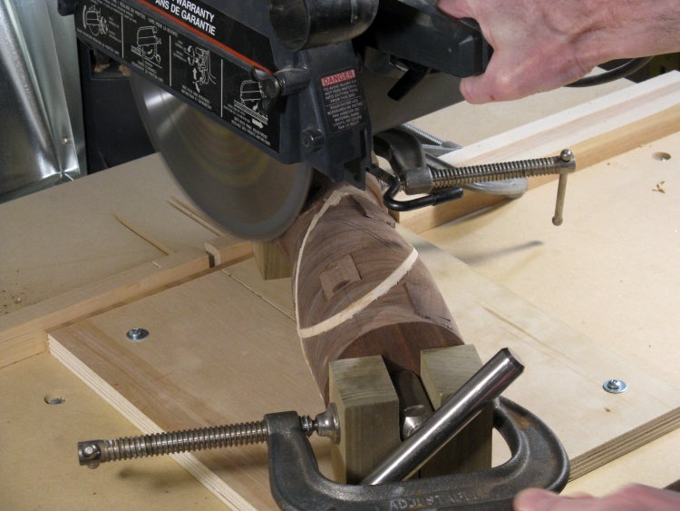
Spinning blade headed for edge of piece (cue suspenseful music...)
This would be the saw partway through the cut, except the shutter snapped too soon.
Those keen of eye may notice that there are now two inserts in the vessel rather than the one above. That's just because I used photos of the the cuts for the third insert rather than the second.
Those keen of eye may notice that there are now two inserts in the vessel rather than the one above. That's just because I used photos of the the cuts for the third insert rather than the second.
Widening the cut with a second stroke
The width of the cut for the first maple insert was 0.17" wide due to the width of the mitre saw blade. However my radial arm saw blade is only 0.11". So after taking the first slice, I loosened the jig off, moved it 0.06" and took a second slice.
0.06" is just a bit thicker than a dime.
0.06" is just a bit thicker than a dime.
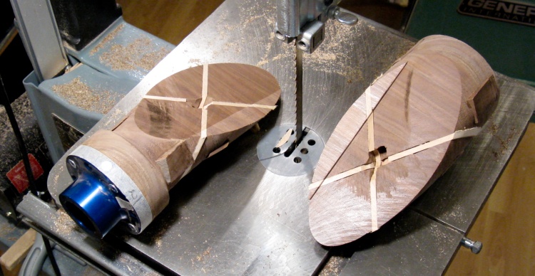
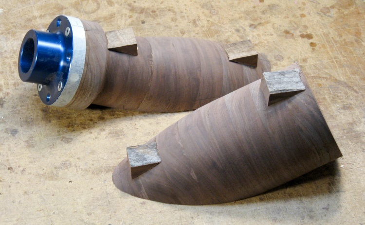
The two halves after being cut apart on bandsaw
Then the pieces were cut apart on the bandsaw. I handheld the wood and aimed it to be sure to keep the blade between the two just-cut walls.
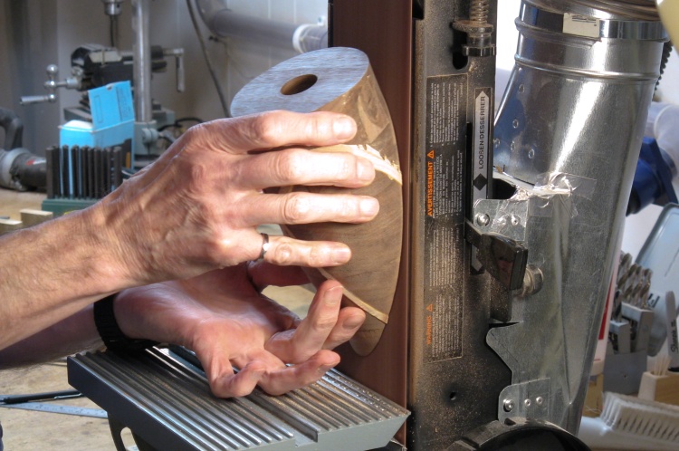
Flattening the face on the belt sander
The two halves had the small protruding bits sanded off using the belt sander so each face was smooth.
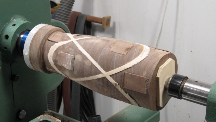
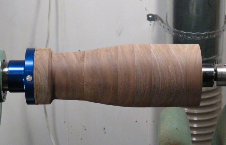
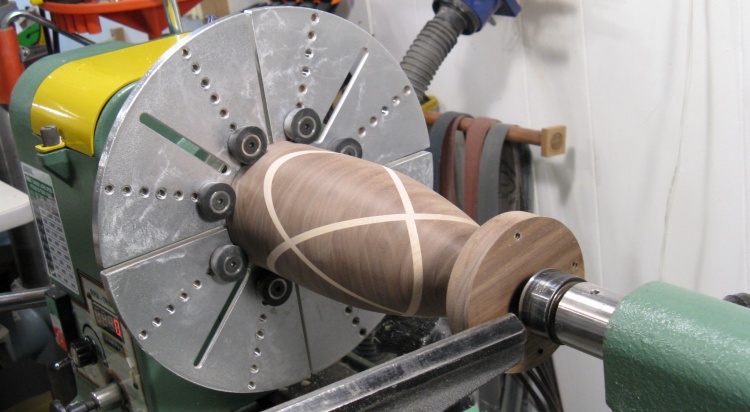
All three pieces in and ready to turn
Then the same procedure as before of adding clamping ramps, gluing in maple piece and trimming off the excess wood was done.
That brings us to this noteworthy point where the blank is completed and it is ready to begin final turning.
Here it's been mounted on the lathe again with an end cap glued on to let the tailstock support the top end.
That brings us to this noteworthy point where the blank is completed and it is ready to begin final turning.
Here it's been mounted on the lathe again with an end cap glued on to let the tailstock support the top end.
Turning
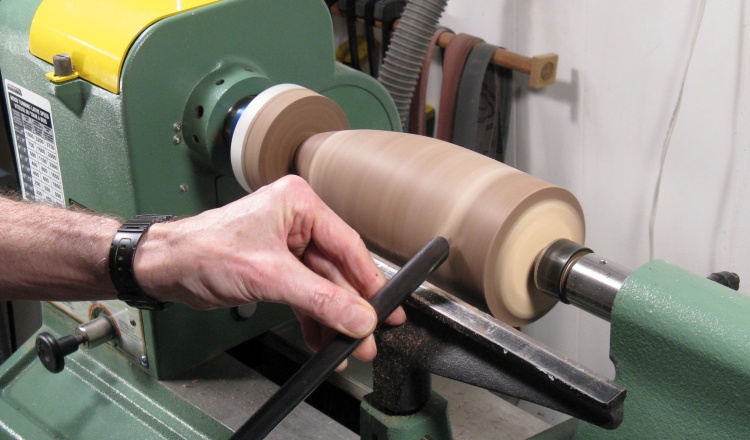
A final bit of shaping
The vessel was already pretty close to the final shape, but I cut off all the protruding bits and narrowed the base. This shot shows some fine scraping being done to smooth off a section near the top.
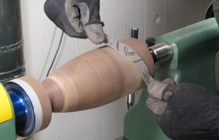
Sanding the surface
And the shaping was inevitably followed by sanding. I started with the 120 grit shown here and worked up to 320.
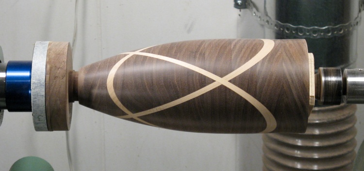
A much shinier outside
The outside was much more presentable after the sanding.
Hollowing
That bottom bit wasn't quite strong enough any more
The first step before hollowing was to pry off the temporary-glued end cap. Unfortunately, a joint at the bottom wasn't quite up to supporting the minor sideways force that caused, and one piece became two.
Gluin' er back together
Nothing for it but to glue'er back together.
And that lasted just until I started hollowing and then it broke apart about a millimeter further along.
Hmmm. A narrow cross-grain section is the problem, so I added a dowel; I turned a walnut dowel whose grain ran longitudinally, drilled both sides of the joint, inserted the dowel in the holes and glued it. Fortunately, that seemed to add enough strength to keep things together for the rest of the hollowing.
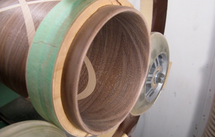
A wooden anti-marking ring
I'd happened to run across a wood ring in one of my many piles/boxes/drawers/shelves of scrap wood pieces and it looked about the right size to act as a wheel shield for this vessel. I dug it up and it turned out to be pretty much perfectly sized so I taped it on.
Faithful readers of these pages (God bless both of them) will recall that the shield prevents the vessel surface from being compressed by the rubbery wheels.
Faithful readers of these pages (God bless both of them) will recall that the shield prevents the vessel surface from being compressed by the rubbery wheels.
Starting the hollowing
The hollowing has been started and the cutter is less than a quarter-inch into the vessel so far.
I was being careful to take only thin layers off to prevent re-breaking the bottom of the vessel.
I was being careful to take only thin layers off to prevent re-breaking the bottom of the vessel.

Part of the way in
Here it is a bit later, hollowed to a couple inches deep.
It's tough to make a smooth cut with the small cutter used for the hollowing, so the walls tend to be pretty rough after the main hollowing process.
It's tough to make a smooth cut with the small cutter used for the hollowing, so the walls tend to be pretty rough after the main hollowing process.
Boring photo (get it? get it?)
When hollowing close to the top of the vessel you can see the progress by looking in the end, but for most of the vessel the cutter position is judged by feel and the laser spot position.
I usually expand the center hole out a bit, then cut from there to close to the edge, then clean up the edge. The individual cuts were maybe 0.01" deep, so I'd do 10 or 20 to get 0.1 or 0.2" deeper before moving to the next stage.
I usually expand the center hole out a bit, then cut from there to close to the edge, then clean up the edge. The individual cuts were maybe 0.01" deep, so I'd do 10 or 20 to get 0.1 or 0.2" deeper before moving to the next stage.
It was about at this point where our water heater blew its top. We had gone out for lunch on a Sunday and arrived home about 45 minutes later to find a quarter-inch of water at the bottom of the basement stairs and more bubbling out the top of the heater.
The bad news was that this was nowhere near the drain, but the good news was that it had found the sump pit, so the water ceased rising and spreading. Fortunately(?) the basement floor is rather uneven so maybe only 15% of the basement was wet - a pretty easy cleanup all told.
This heater we had put in 19 years ago, so you can't complain too much about that. We bought the current version of the same one from the same place and they were able to install it the next day. There's about 36% inflation over those 19 years, but even accounting for that, the heater cost more than twice the old one, and installation was four times as much. And we were happy to pay it: the tap water in winter would make for a really, really cold shower. Not that we can't grouse about it, of course. So after some sloshing, mopping, shopping, shop-vac-ing, rearranging and of course paying, it was back to woodworking;
Hollowing done and inside sanded
After the main hollowing, I switched to larger cutting bits to smooth off the walls, followed by way too much sanding. This photo shows the top edge after the smoothing and sanding was complete.
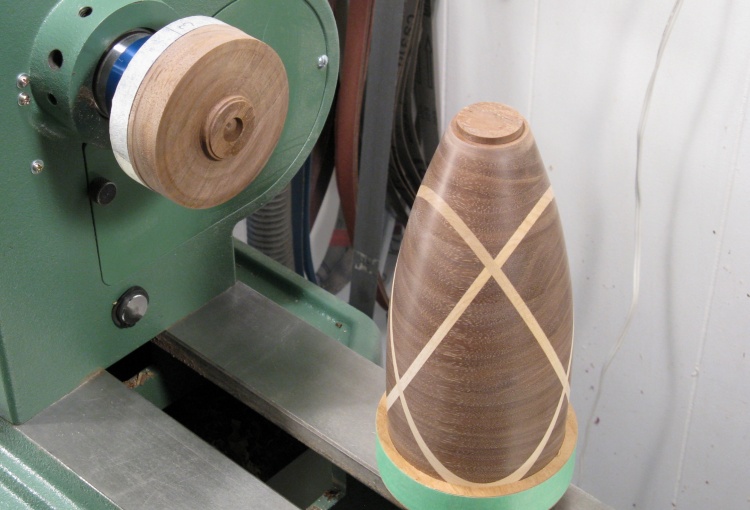
Vessel flipped around to remove the bottom
The next step was to remove the bottom section. I often start by cutting most of it off with a saw, but I wanted the extra length of material to give me a bit more room to shape the rather small bottom.
The vessel was disconnected from the baseplate and flipped around so the top could be gripped by the large aluminum jaws.
The vessel was disconnected from the baseplate and flipped around so the top could be gripped by the large aluminum jaws.
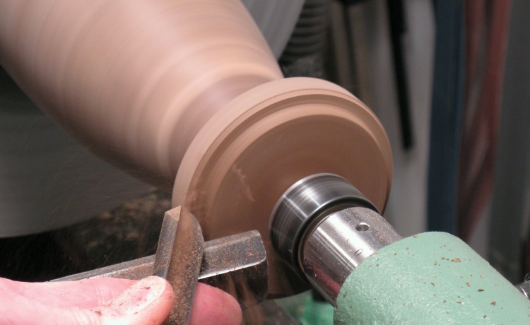
Slicing away the bottom
This shot shows the bowl gouge starting to cut away the excess wood.
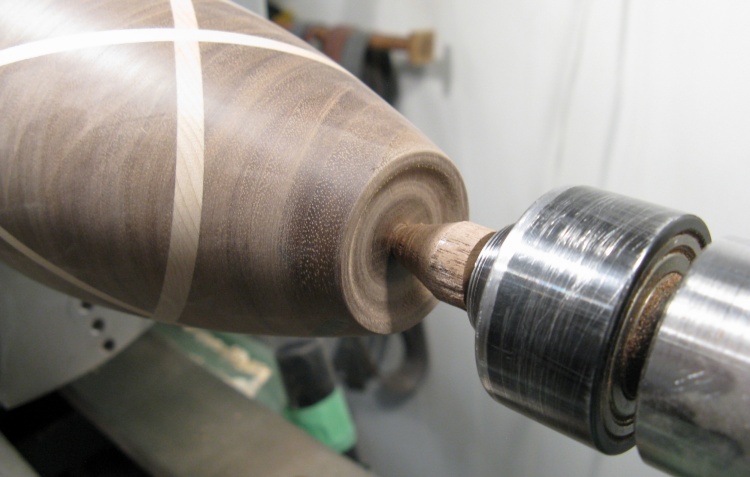
Bottom foot formed
Here the bottom foot has been formed and most of the excess wood has been removed, leaving just a small-diameter bit in the center.
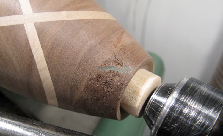
Post flying-off-the-lathe divot
Then I was just cutting away a bit more wood in the center when I had a catch (where the tool abnormally grabs the wood) which broke off the bottom stub and flung the vessel across the room, although admittedly only the short way. Fortunately the only damage was a couple divots; one near the top and this one at the bottom.
I sanded the bottom flat and added the light-colored piece of wood to accept the tailstock point and put it back on the lathe. Then I had to get rid of the divots. This was mostly done with some light scraping to minimize the amount of material removed.
I sanded the bottom flat and added the light-colored piece of wood to accept the tailstock point and put it back on the lathe. Then I had to get rid of the divots. This was mostly done with some light scraping to minimize the amount of material removed.
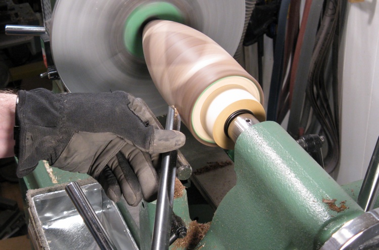
Some careful scraping of another divot near the top
Unfortunately, it's difficult to re-center a turning on the lathe if the center marks are no longer there. I was able to get within about 0.015" (about the thickness of cereal box cardboard) but that wasn't close enough to use a normal speed without reshaping some of the vessel.
Instead, I used a very low speed - around 120 RPM - which is why the vessel lines are just blurred rather than invisible in this 1/20 sec exposure*. That let me keep pressure on the tool to scrape all the way around the slightly offset circumference. Here I'm working on the top divot, again using a light scraping action.
Instead, I used a very low speed - around 120 RPM - which is why the vessel lines are just blurred rather than invisible in this 1/20 sec exposure*. That let me keep pressure on the tool to scrape all the way around the slightly offset circumference. Here I'm working on the top divot, again using a light scraping action.
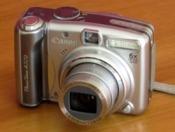
10 years old and still chuggin'
*I use a 10-year old Canon point-and-shoot for the photos (camera trivia; it recently rolled over its photo numbering meaning it has taken 10,000 photos). It's set for 200 ASA to get decent resolution and with its not-especially-fast f/2.8-4.8 lens, this usually results in fairly slow shutter speeds. Fortunately it has decent image stabilization performance so handheld pictures are still usually sharp. The light in my shop (6 fixed and 9 Luxo-style lamps) produce lots of light for working, but the camera always likes more. As a result, shutter speeds vary from 1/15 to 1/80 second and seldom faster. This explains the motion blur in those hand-sanding photos...

Some final sanding
And then the scrape marks needed to be sanded out, so I did the 120 - 180 - 220 - 320 grit sequence once again.
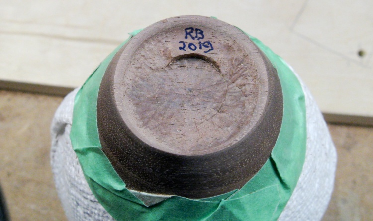
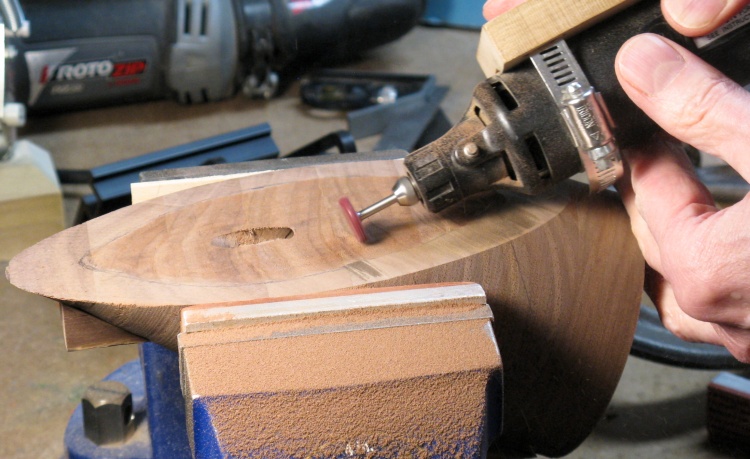
The bottom was given a coarse texture
The bottom was pretty small for the normal inset initial-circle I usually use, so I left a small arc of material for that and used a Dremel with a small spherical cutting bit to give a convex shape and a rough texture to the rest of the bottom.
In this shot the vessel is wrapped in paper towel to prevent scratches while working on the bottom.
In this shot the vessel is wrapped in paper towel to prevent scratches while working on the bottom.
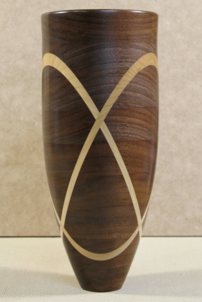
Woodworking done
That was it for the woodworking. This photo shows the finished vessel from one of its better angles.
Finishing
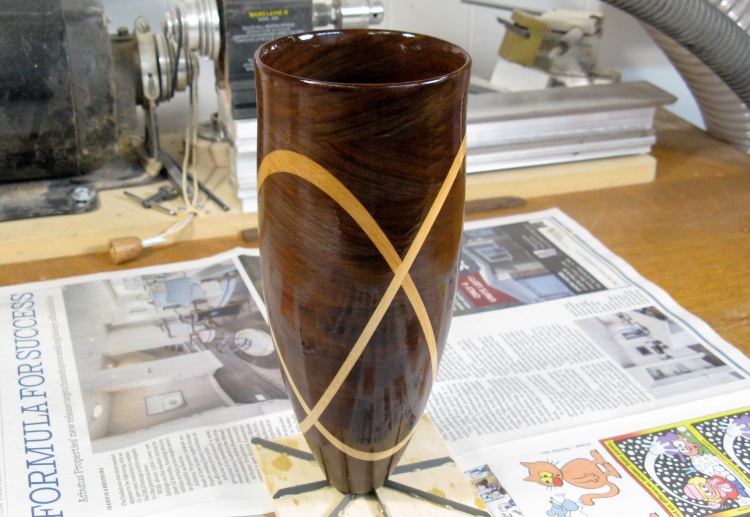
The first coat of varnish
The vessel got the standard three coats of Fast-Drying Polyurethane applied with foam brush and cloth.
Here the first coat has been applied. For some reason the polyurethane didn't live up to its name and it took a couple days for that coat to dry, but the subsequent coats were pretty typical.
Here the first coat has been applied. For some reason the polyurethane didn't live up to its name and it took a couple days for that coat to dry, but the subsequent coats were pretty typical.
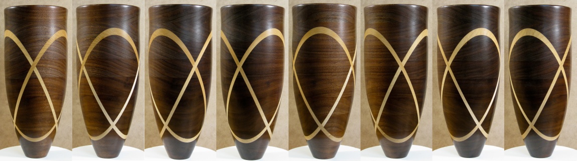
Around the vessel in 8 steps
Done and dried


