Unlike a fair number of my projects, this one wasn't driven by an actual need - there was no blank wall calling out for a carved panel. However, I had seen a pattern in an interior design shop once and kind of liked it. It seemed to me reminiscent of tree branches in profile, and I thought it might look nice done in wood. I checked out some variations of this design and a few other patterns but none of them tickled my fancy any...um...fancier, so I stuck with this original one.

The outline of the hoped-for result

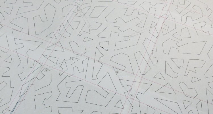
Umm...nope, uh-uh and nah
As mentioned, I first checked out a few other patterns based on repeating elements, a few of which are shown here.
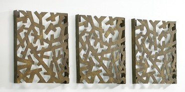
Original inspiration
And just for the record, here is the set of original wall panels that this one is modelled on.
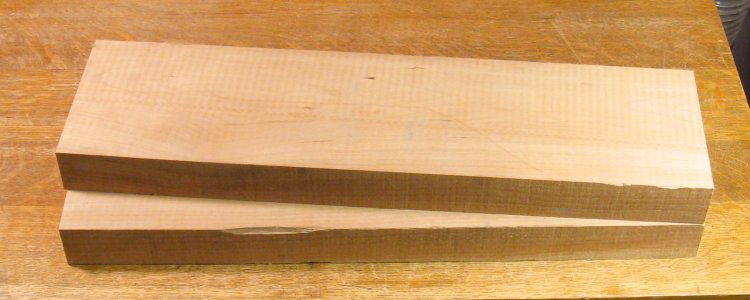
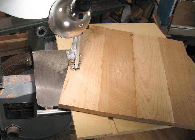
Started with 2" planks
I decided to use a single plank for the wood to try to keep the color consistent, so I started with a 6 foot plank that was 2" thick, and cut off a couple 24" sections as shown here.
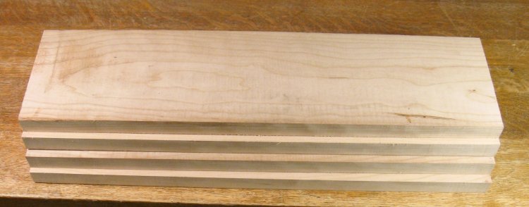
Four 1" planks
Each of those was cut into a couple 1" planks using the bandsaw.
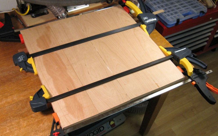
Laminating planks into a 24" square
The four pieces were edge-glued together to make one large panel. To simplify the process, I first glued together pairs and then here the two pairs are being glued together.
Rough-cutting to a circular shape
The panel had an appropriate-sized circle marked on it and then was cut out using the bandsaw.
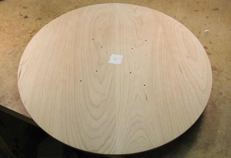
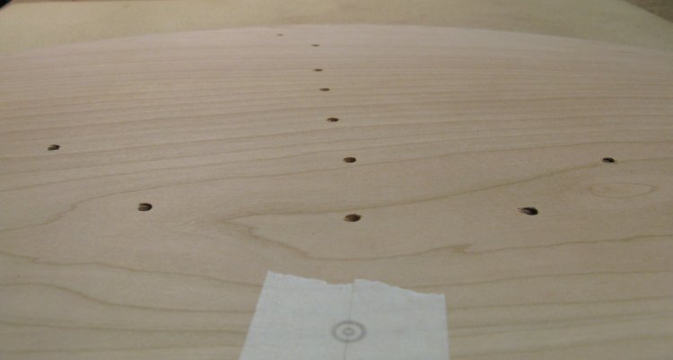
Pattern marked for mounting holes
To mount the piece to the lathe, I used an adjustable chuck, mostly because it has a set of large "jaws". In this case, I removed the normal hardware from the jaws, reducing them to simple plates. Usually the mounting screws for the chuck go into a thick throw-away piece of the wood being turned, but my wood was going to eventually be pretty thin and my preference was to not to add an extra piece just to accept the screws. However I was lucky enough to be able to arrange to have the eight screws come through only in "hole" sections that would be cut out later.
This is a shot of the pattern with the chuck slots and mounting holes marked. The hole locations were transferred to the wood and they were drilled right through for the screws.
This is a shot of the pattern with the chuck slots and mounting holes marked. The hole locations were transferred to the wood and they were drilled right through for the screws.
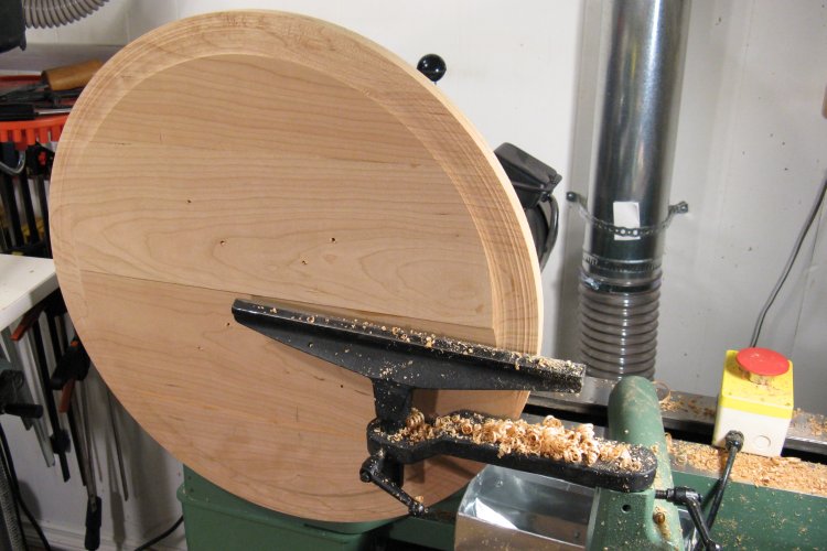
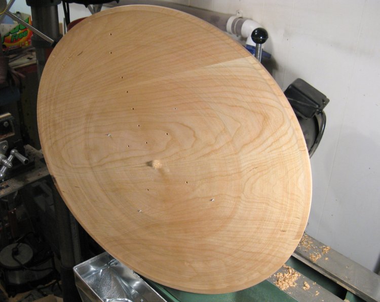
The blank mounted on the lathe and offset by 90 degrees
Here the wood has been mounted to the lathe. You can see the eight mounting holes and it looks a bit like the screws are sticking through, but those are just wood chips since the screw ends don't reach the surface.
Of course normally it wouldn't be possible to turn a 22" diameter piece on a 16" lathe, so here the lathe head has been rotated 90 degrees so the wood is clear of the bed. You could really turn any diameter like this, limited only by the height from the floor and the foolhardiness of the turner.
Of course normally it wouldn't be possible to turn a 22" diameter piece on a 16" lathe, so here the lathe head has been rotated 90 degrees so the wood is clear of the bed. You could really turn any diameter like this, limited only by the height from the floor and the foolhardiness of the turner.
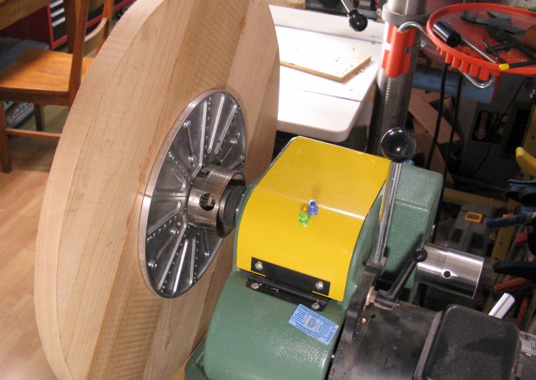
Rear showing the "jaws"
This shot of the back shows the chuck with its large jaws screwed to the back of the piece. I was fortunate in that the wood manages to (barely) clear the protruding lathe leg near the bottom of the piece.
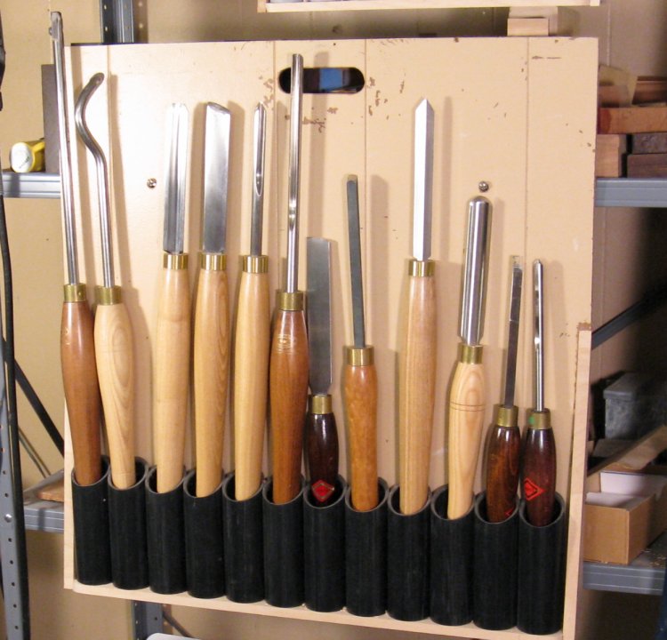
My large (mismatched) turning tools
And we'll take a brief tangent here to show the large turning tools that I used. This is a bit of a mismatched set (bonus points to spot the home-made handle). The tools vary in length from 26" on the left to 16" on the right. All arranged in the finely-crafted painted-wall-panelling-and-pipe holder (with convenient carrying handle) that gets hung on the shelf beside the lathe when needed.
Starting on the front
Here the turning has been started on the front of the piece.
One problem with rotating the lathe head 90 degrees is the controls that used to be on the front are now on the side behind the wood. Like the on/off switch. It's not too bad starting up the lathe but you don't want to be leaning over a two-foot piece of spinning wood to turn it off. As a result, the Big Red Emergency Switch seen on the right was used to turn off the lathe.
One problem with rotating the lathe head 90 degrees is the controls that used to be on the front are now on the side behind the wood. Like the on/off switch. It's not too bad starting up the lathe but you don't want to be leaning over a two-foot piece of spinning wood to turn it off. As a result, the Big Red Emergency Switch seen on the right was used to turn off the lathe.
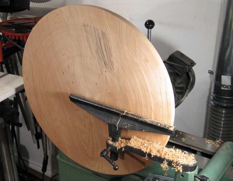
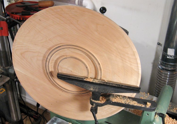
Front almost done - one low spot left
The front of the piece is slightly convex with about 1/2" of curvature over the 22" diameter. Here the front is mostly shaped. The dark area is a low spot (scribbled upon with pencil) down to which everything else must be cut to maintain a smooth profile.
Power-sanding the front
And at this point the shaping has been done, and a random orbital sander was used to remove any imperfections in the turning (all too obvious at the bottom of the piece). The lathe wasn't turning for this process - the shaft was locked so the wood couldn't rotate.
The front done, with center marked on tape
This shows the completed front. Before removing it from the lathe, I added some masking tape and marked the center so I could make sure it was centered when it was remounted.
Thickness-gauging holes
The next step was to turn the back so the piece had a consistent thickness. To help gauge this, I added some holes (that were in sections that would later be removed) to be able to check the thickness from inside to outside. I modified a popsicle stick into a gauge that let me check thickness at each hole.
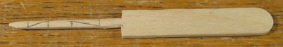
Precision type PS gauge
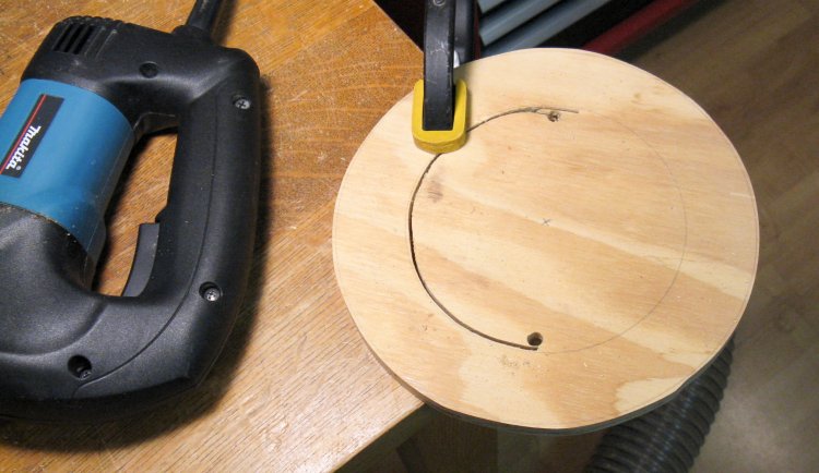
Cutting a ring-shaped spacer
I needed to mount the flat plate of the chuck to the convex shape of the front, so I made a spacer - what was essentially a big plywood washer - to go between them. Here the jigsaw is taking a little breather after cutting out the first half of the plate.

Lathe "jaws" mounted to front with ring spacer
This shows the chuck mounted to the front of the piece with the spacer in between (visible between the nearest two screws). I was able to reuse the screw holes.
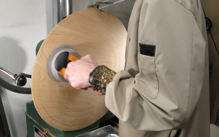
Hollowing the back on the lathe
Then the wood was remounted to the lathe, except the back side is out this time.
Of course now that the wood is being cut thinner, the length of the mounting screws becomes an issue. You can see here that I have cut the proper profile everywhere except where there is a mounting screw sticking through.
Of course now that the wood is being cut thinner, the length of the mounting screws becomes an issue. You can see here that I have cut the proper profile everywhere except where there is a mounting screw sticking through.
Back hollowing completed
To finish it off, I cut off the ridges with only half the screws in place; first I removed the inside ring of screws while I cut the outside ridges, and then vise-versa.
This shows the back complete except for a small center nub that it wasn't practical to remove on the lathe. That was later removed by hand with chisel and spoke shave and then sanded smooth.
This shows the back complete except for a small center nub that it wasn't practical to remove on the lathe. That was later removed by hand with chisel and spoke shave and then sanded smooth.
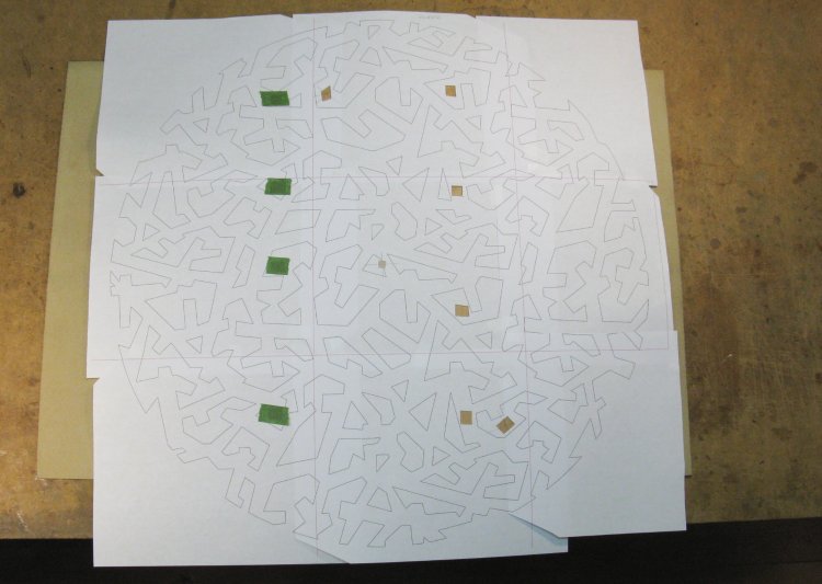
Pattern taped to front
I made a full-sized pattern that could be positioned on the wood. Of course the average printer does only 8.5 x 11 sheets, so the pattern is nine sheets taped together. I cut out some holes for alignment and taping and here the pattern can be seen taped down to the wood.
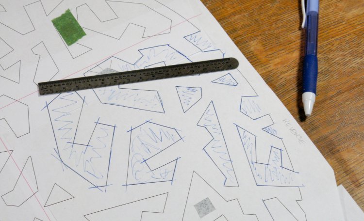
Tracing the pattern
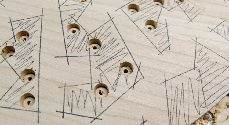
The pattern was transferred to the wood using carbon paper. I did a small section at a time and used a ruler to make accurate lines. I also scribbled in the sections that were to be cut out to help avoid any confusion as to which side of the lines to cut.
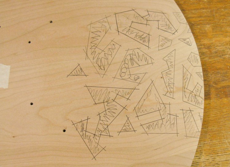
Pattern on wood
The pattern showed up pretty well and I was happy that I didn't get any smudging of the marks as I worked on it.
After some consideration, I settled on using a jigsaw to cut out the shapes. I couldn't see doing it with a hand saw or even a scroll saw, however I was concerned about the noise and vibration of the jigsaw. A buddy of mine once said that the jigsaw was the most possible noise for the least possible effect and I completely agreed since I had endured years of the cheapest crappiest B&D jigsaw. However, I finally splurged for a good one which is well made, has tight tolerances, a selectable speed, an adjustable aggressivness of cut and even a light. I used a narrow blade, a low speed and a non-agressive cut setting and this actually worked very well.
After some consideration, I settled on using a jigsaw to cut out the shapes. I couldn't see doing it with a hand saw or even a scroll saw, however I was concerned about the noise and vibration of the jigsaw. A buddy of mine once said that the jigsaw was the most possible noise for the least possible effect and I completely agreed since I had endured years of the cheapest crappiest B&D jigsaw. However, I finally splurged for a good one which is well made, has tight tolerances, a selectable speed, an adjustable aggressivness of cut and even a light. I used a narrow blade, a low speed and a non-agressive cut setting and this actually worked very well.
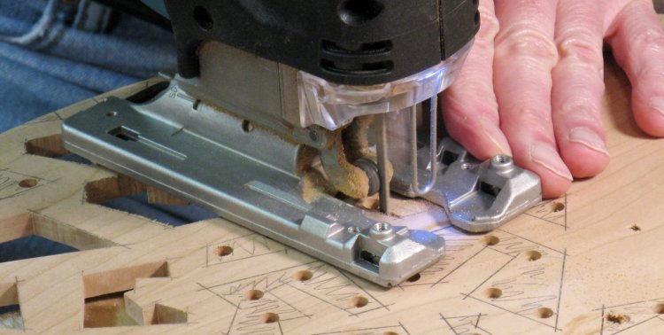
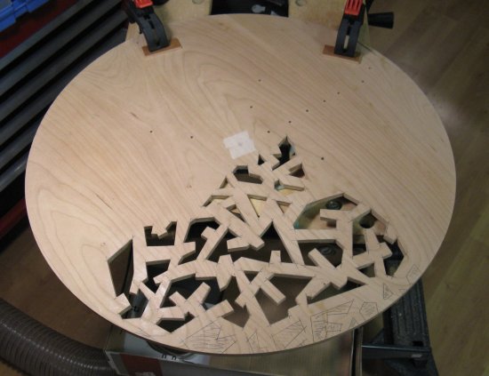
Cutting holes with the jigsaw
I first needed to drill holes to start cuts, so a number of 1/4" holes were strategically drilled in each section to be cut out.
Multi-stage hole drilling
Due to the curved shape of the wood, it wasn't really practical to have a solidly-connected backing board for drilling. As a result, some of the drill holes caused splinters to break away from the bottom side. To prevent this, I did the holes in a three-step process;
1. drill halfway through from the top;
2. drill a small guide hole all the way through, and
3. Using a slightly smaller bit, drill from the bottom to remove the remaining wood.
That was obviously more time-consuming, but it eliminated the splinters.
1. drill halfway through from the top;
2. drill a small guide hole all the way through, and
3. Using a slightly smaller bit, drill from the bottom to remove the remaining wood.
That was obviously more time-consuming, but it eliminated the splinters.
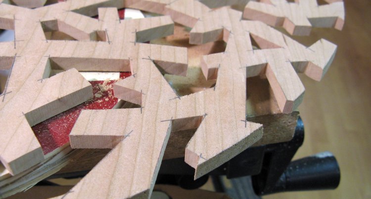
The first group of holes done
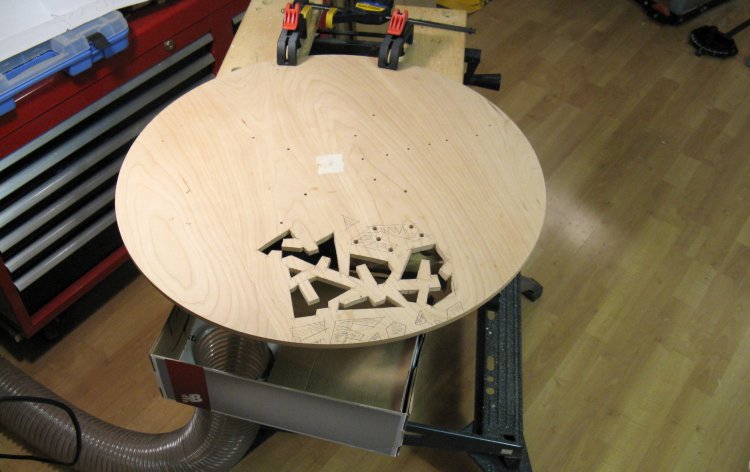
Here the first few holes have been cut out. I left the edge holes for last to delay having fragile edges to contend with.
In this photo you can see the dust control consisting of a 4" flexible hose from a branch of the dust collection system, connected to a shoe-box duct (New Balance for those unnaturally interested in shoes) that I attached to the Workmate.
In this photo you can see the dust control consisting of a 4" flexible hose from a branch of the dust collection system, connected to a shoe-box duct (New Balance for those unnaturally interested in shoes) that I attached to the Workmate.
Pieces to make jig-saw sander
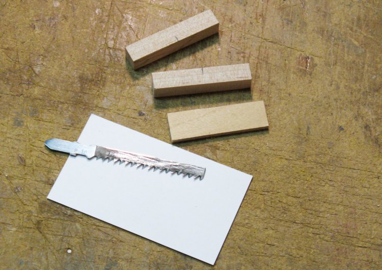
At this point the spectre of sanding reared its ugly head. How was I going to sand 8.3 linear kilometers of edges that I had cut? I really needed some kind of portable power sander and after some thought figured the best plan would be to just buy an attachment for the jigsaw.
Except it turns out they don't really make sanding adapters for the jigsaw - a web search turned up mostly patents for some crude sanding attachments.
Well, it isn't rocket science so I figured I'd make my own. That way, even if it didn't work there wouldn't be a huge fireball on the launch pad. With that jaunty self-assurance, I assembled an old blade with a thin piece of plywood and some small blocks to provide support.
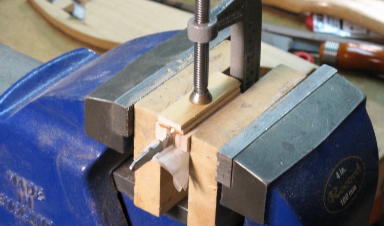
Sander attachment being glued
With a generous amount of epoxy, these pieces were combined and held together as shown here. After the glue hardened, the wood was sanded down to provide sharp corners. Finally, sandpaper was cut to size and stuck on with a temporary latex adhesive.
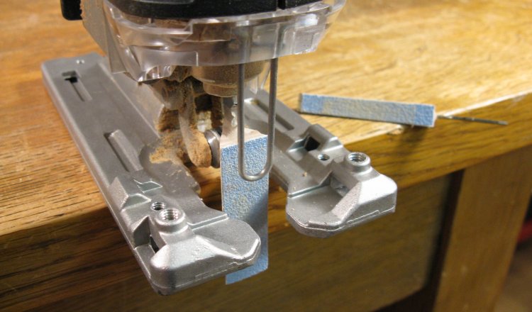
Sanding attachment on the saw
And here the sander is shown mounted to the jigsaw. I made a second smaller one as well which can seen in the backgound. These are swapped out the same way as the blades - just work the blade release and remove or add one.
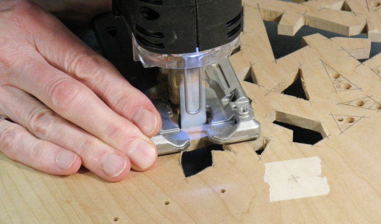
Sanding an edge
The sanding attachments worked great and this shot shows an edge being sanded. The saw was set to low speed and only light pressure was used. The sharp edges of the attachments let them get into most corners, but some were too tight and had to be done by hand.
After the power sanding, I used needle files to finish any edges or corners that needed attention. In all with tracing, drilling, cutting, sanding and filing, I think I averaged about 1.5 minutes per side of the cutouts. There were about 110 holes with just over 1000 sides and it took a bit over three weeks to complete them.
After the power sanding, I used needle files to finish any edges or corners that needed attention. In all with tracing, drilling, cutting, sanding and filing, I think I averaged about 1.5 minutes per side of the cutouts. There were about 110 holes with just over 1000 sides and it took a bit over three weeks to complete them.
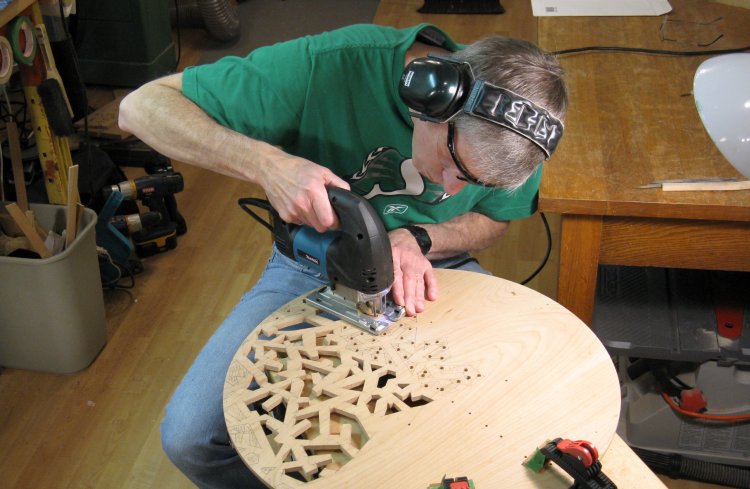
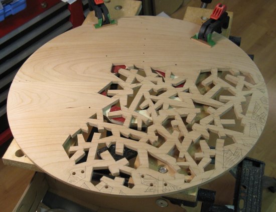
Plenty more holes to go
This shows the setup I used. The piece was clamped to the Workmate with the area to concentrate on positioned above the dust collector.
One-quarter done
Almost half
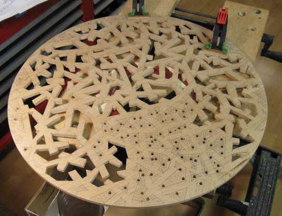
Three-quarters done
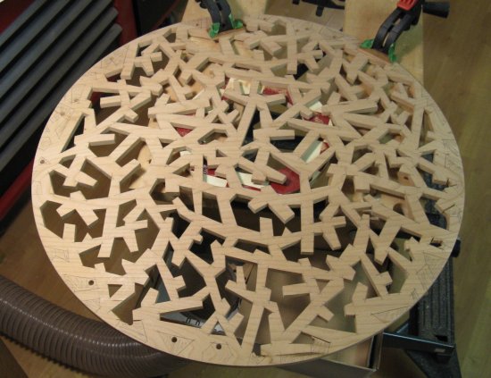
Everything but the edges
The shots above show the progression of cutting the holes. I generally marked a group, cut some of the openings out, then sanded and filed those. Then I repeated the cut/sand/file sequence so I left groups of finished holes rather than have to do all the sanding at once.
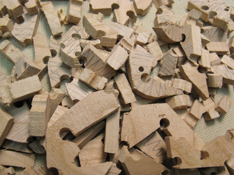
Cut-out pieces
This is a completely unnecessary shot of the cut-out pieces.
Lines to be removed
Here you can see some of the completed edge holes. There are still some carbon-paper marks that need to be removed. This was done by hand-sanding the top side using a sanding block.
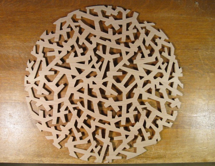
All holes cut and top sanded clean
This shows the piece with all the openings cut out and the surface sanded to remove the marks.
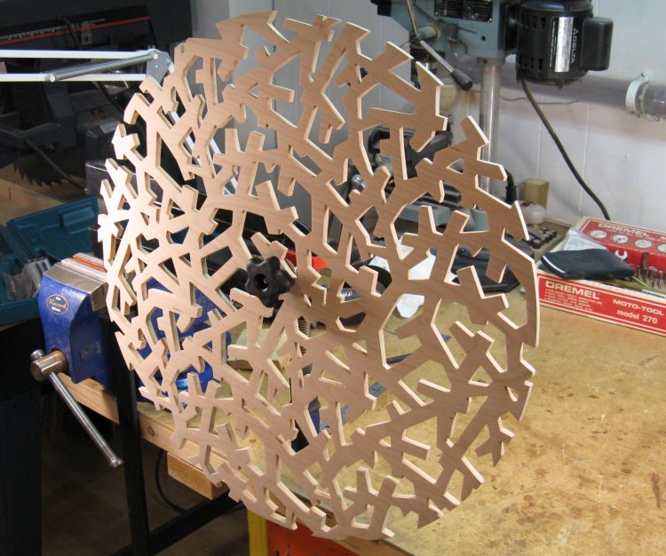
Mounted for varnishing
To apply the varnish, I made an axle to mount the piece. The bench vise held the bar of a large clamp, which itself held a 1/4" bolt. I added some washers, mounted the piece on the bolt and held it in place with a threaded knob.
I used small sections of cotton cloth dipped in varnish to pull back and forth to coat the edges, and it was just bunched up and rubbed on the front and back to do the faces. It took a bit over an hour to put on each coat.
I used small sections of cotton cloth dipped in varnish to pull back and forth to coat the edges, and it was just bunched up and rubbed on the front and back to do the faces. It took a bit over an hour to put on each coat.
First coat of varnish on
Here the piece has the first coat of varnish on it.
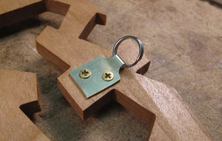
Mounting loop
To mount the unit to the wall, I added a little metal loop (a tiny keychail-style ring) using a brass attachment plate. A couple tiny screws holds the plate to a convenient "strut" near the top. A simple nail is used as a hangar, so the mounting mechanism isn't visible from the front.
The panel is oriented with the wood grain horizontal.
The panel is oriented with the wood grain horizontal.
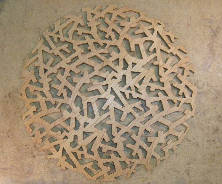
Front view, complete
Front view of the completed unit.
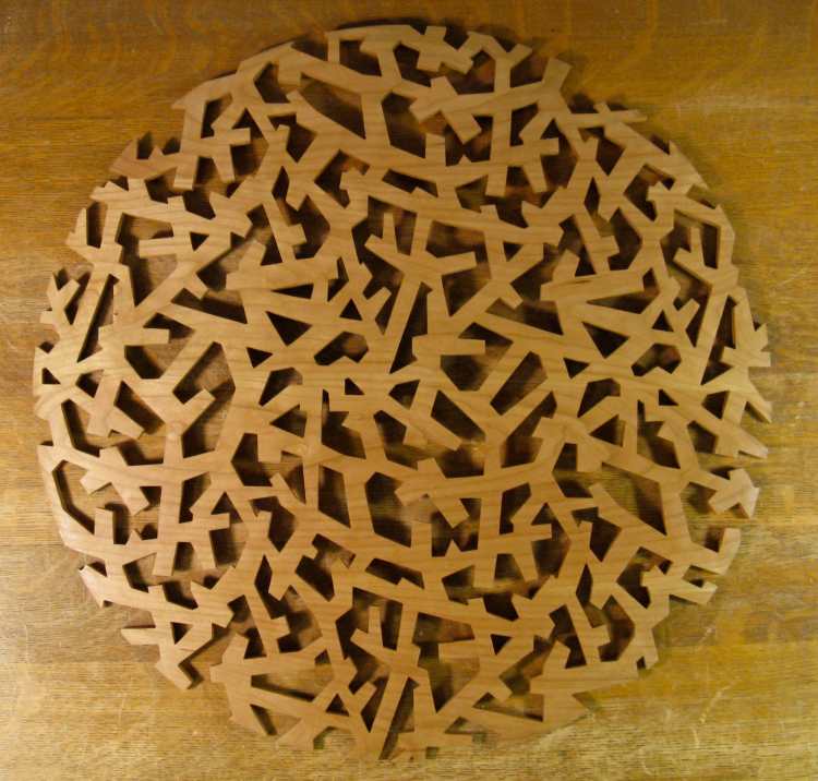
Rear view, complete
Very similar rear view of the completed unit.
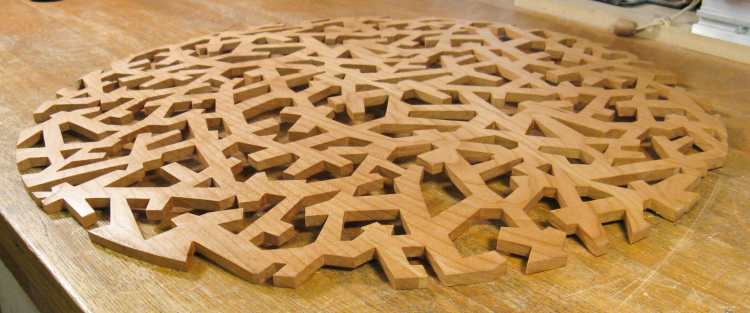
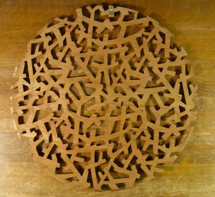
Low angle shot
And an oblique view for variety.


