After I decided to make a wastebasket, my natural proclivity for slightly weird things drew me toward modelling it on a real-life object rather than making something artsy (or perhaps it was my natural proclivity for not having any artistic talent). At any rate, I drew up a few candidates for myself and spouse to compare and we decided on the turned chess rook, largely since it looked most like what it was.
Of course the rocket was pretty cool, but it would have somewhat tougher to make a functional wastebasket so it was "left on the cutting room floor" along with the other runner-ups.
Of course the rocket was pretty cool, but it would have somewhat tougher to make a functional wastebasket so it was "left on the cutting room floor" along with the other runner-ups.
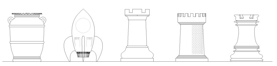
Some options considered
And of course you can't do any kind of turning without a plan that has a nice purple center-line, so that was the first step;
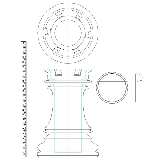
The plan, including cover and precariously-balanced virtual 24" ruler
So at about 18", this will be a pretty large chess piece. This of course brings up the question "so what is the largest chess piece?". A brief search suggests that it might be a king in St. Louis at just under 15' high. Given the ubiquity of the game of chess and the relatively low level of detail required to make a big one, I have to admit that I'm a bit surprised that there is not something bigger. I mean, I've seen bigger "world's biggest" moose, wheat sheaves, coffee pot, grasshopper, etc. How can it be that no-one has ever say, added a few lightweight pieces to an old lighthouse and made it into a REALLY big chess piece? Maritime provinces, the ball's in your court...
Anyway, the next step was finding a big enough piece of wood. It needed to be just over a foot in diameter and about 18" high. The ideal solution was to find a suitable log since buying turning blanks in that size is nearly impossible. It turned out that we knew someone with sections of a fir trunk sitting unused. They were happy to get rid of some so we dug a path through the snow to the pile and broke a couple likely-looking logs out of the ice that had formed in a mid-winter melt.
Anyway, the next step was finding a big enough piece of wood. It needed to be just over a foot in diameter and about 18" high. The ideal solution was to find a suitable log since buying turning blanks in that size is nearly impossible. It turned out that we knew someone with sections of a fir trunk sitting unused. They were happy to get rid of some so we dug a path through the snow to the pile and broke a couple likely-looking logs out of the ice that had formed in a mid-winter melt.
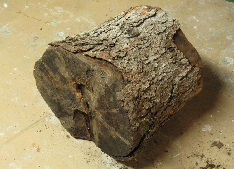
The candidate log thawing out in the basement
I let the logs warm up for a day or so before scraping off the worst of the thawing soil and turf remnants and stripping off the bark. This was the larger of the two, the second being a backup in case there were some difficult knots or some other problem.
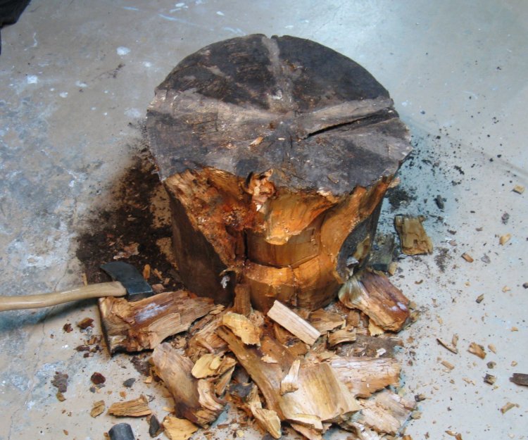
Not as tough as one might hope
And sure enough there was "some other problem". I was thinking that I would chop off some of the wider parts, but the first blow of the hatchet knocked off a big chunk and further chops showed that the wood was already well-rotted. Fine for termites, but wood turning? Not so much.
Of course the second log being of the same vintage was similarly rotted. I did a bit of considering where I could find another suitably-sized and fresher log (in the middle of winter), but didn't come up with any great ideas.
These logs were a few years old which I figured might just be nicely seasoned. However, they had been stored on end, just sitting on the grass. The moral of the storey is probably to store your logs on their sides if you want to avoid quick decomposition
Unfortunately that meant I had to use plan B.
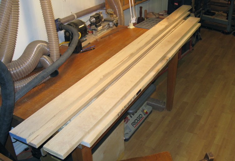
Maple planks
Plan B was going to be rather more work before I could start turning. It involved starting with around 12 board-feet of planks and making a suitable form. Fortunately I had almost enough maple that I had bought on spec for a good price many years ago. I dug that out of the bottom of my wood storage and supplemented with a couple more purchased planks.
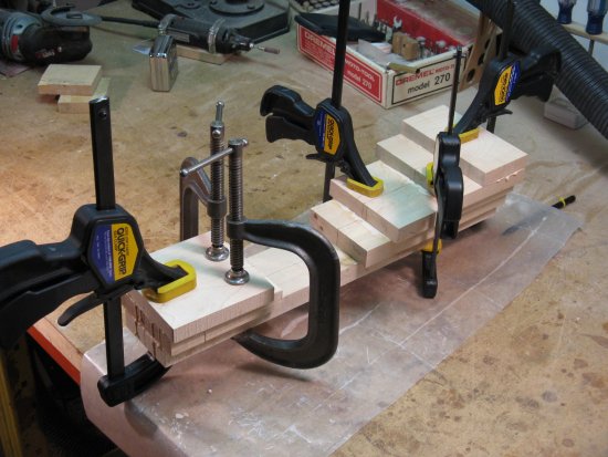
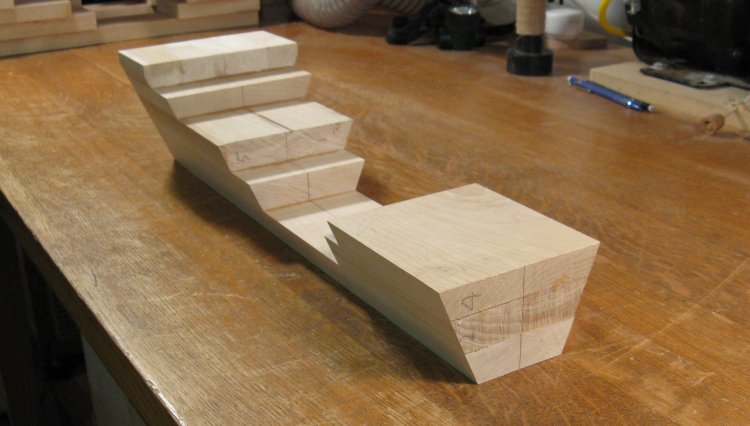
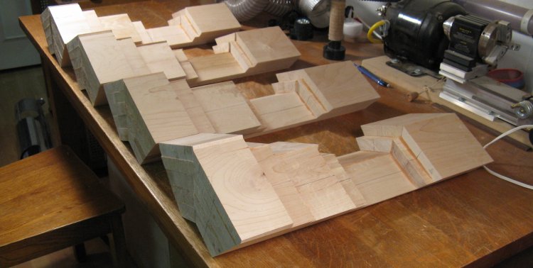
Stackup of planks to make form
This shows the various pieces and how they stack up to form the sections. One advantage of plan B is that much less has to be cut out of the center. Making such a large and deep hole in a solid log would have been a challenge.
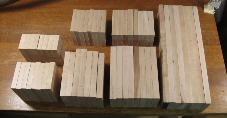
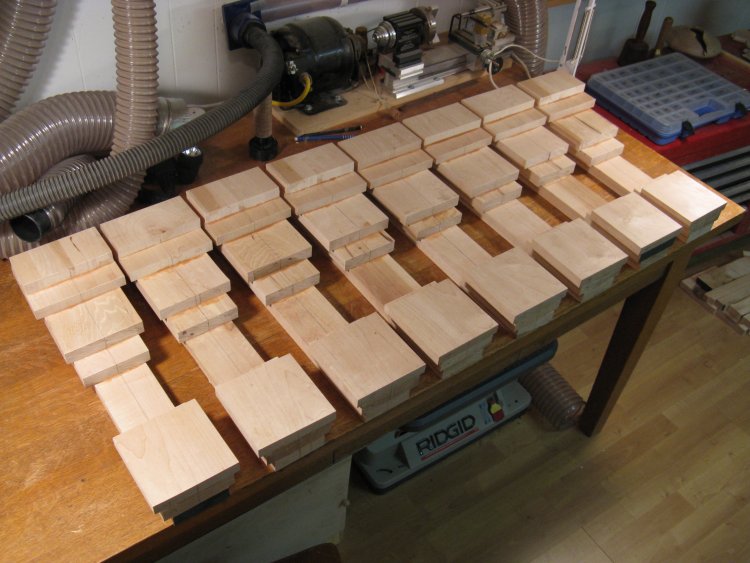
Planks turned into pieces
After a bit of edge-joining to get enough wide pieces, the planks were cut up into the necessary sizes.
And then there was the gluing and clamping;
Gluing
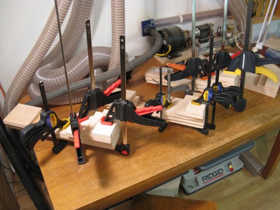
and clamping
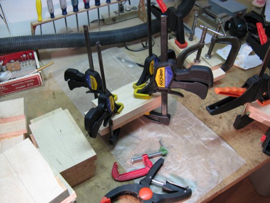
and clamping
and gluing
Pieces glued up
And here the eight pieces are glued up and ready for the next stage.

Mounted on cutting jig
I made a simple jig to aid in cutting the sides. This was just a spare piece of MDF shelf screwed to the assembly. The shelf sat against the rip fence of the bandsaw to maintain a fixed distance for a straight cut.
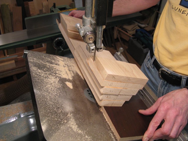
Cutting an edge
The first edge was cut as shown and then the assembly removed, flipped around and reinstalled on the shelf piece so the other side could be done.
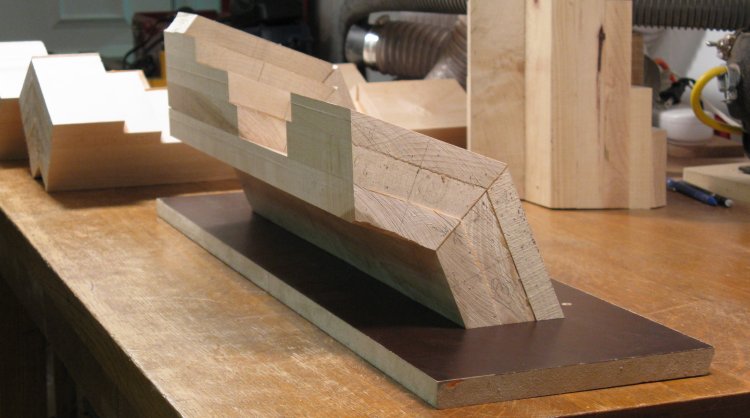
Assembly with sides cut
Those cuts resulted in this vaguely galleon-like shape.
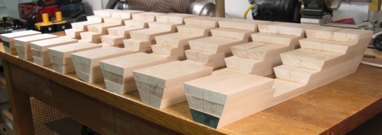
Ready for assembly
And here's the whole fleet sitting at dry-dock and ready for maneuvers.
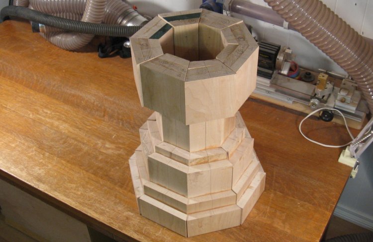
Test fit of the eight pieces
And the first maneuver is the "Octo" which they are just practising in this shot.
A pair of sections being glued
I started as shown here by gluing the sections into pairs.
Four quadrants glued
By gluing the pieces into quadrants, that gave them a nice 90 degree angle between the sides.
One quadrant mounted on jig
I planned to use the jointer to make the sides more consistently straight and ideally make the 90 degree angles more accurate as well. For better registration against the jointer fence, I reused my shelf piece to provide a large flat surface.
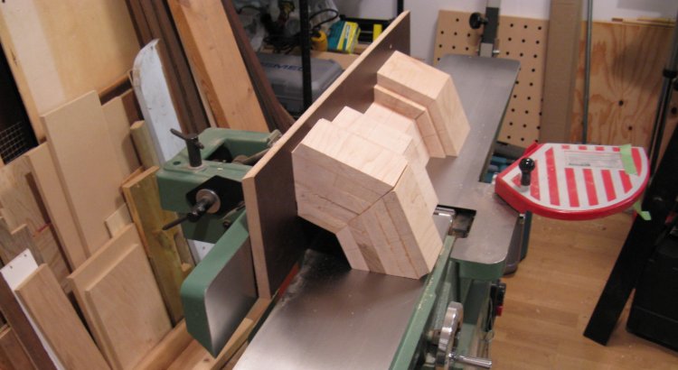
Jointer setup
This setup was run through the jointer a few times on both sides for each piece.
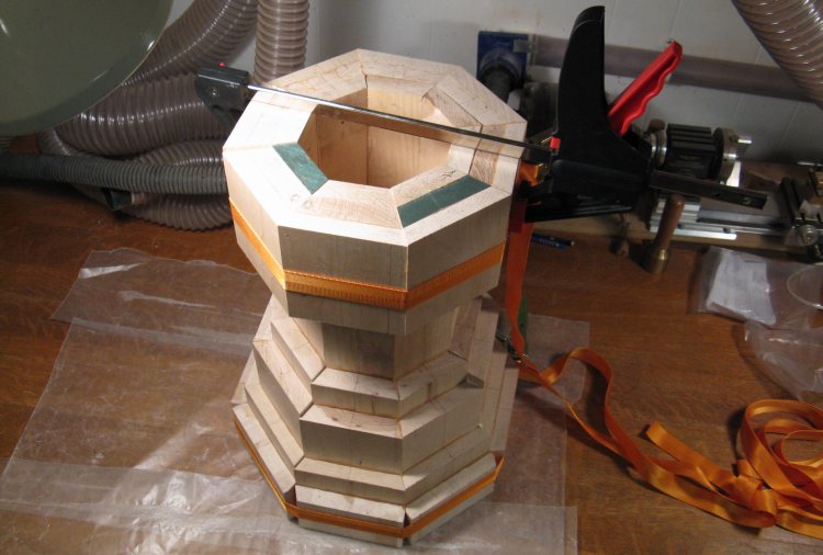
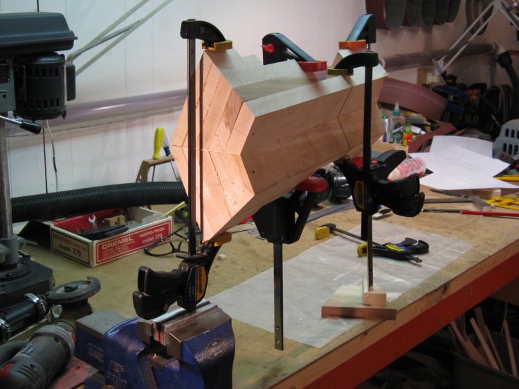
Gluing sections together
And finally the pieces were glued together in two rounds using this strap-clamped setup. The first round I added glue to only 2 joints and when that dried, did the remaining two.
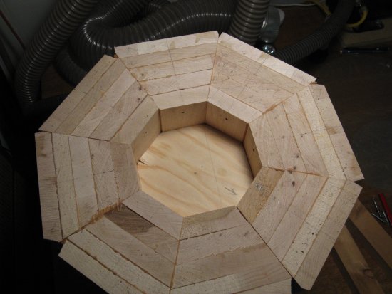
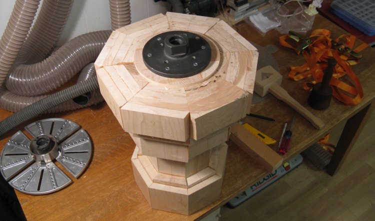
False bottom
So now I had a big hollow core. I ultimately needed to mount that to a plate for turning on the lathe. The trick was mounting it so the centerline was straight. If it was off by a few degrees, then there would be a big dangerous wobble as it spun, and there might not be enough material to get the profile I wanted either.
I decided to do a temporary between-spindle mount so I could cut a recess in the bottom. The recess would be nice and round (making it easy to fit in a round bottom plug) and the floor of the recess would be perfectly level to replicate the alignment of the piece when the recess was cut.
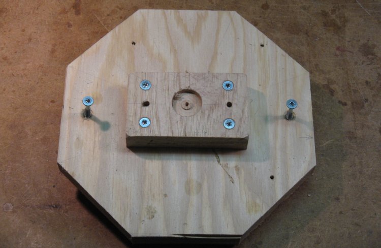
However to do that, I needed to mount the piece on the lathe to cut the recess. To give gripping surfaces, I make a rough octagonal "false bottom" plywood plug and screwed a larger plate on to the top.
I decided to do a temporary between-spindle mount so I could cut a recess in the bottom. The recess would be nice and round (making it easy to fit in a round bottom plug) and the floor of the recess would be perfectly level to replicate the alignment of the piece when the recess was cut.
However to do that, I needed to mount the piece on the lathe to cut the recess. To give gripping surfaces, I make a rough octagonal "false bottom" plywood plug and screwed a larger plate on to the top.
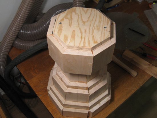
Top plate for temporary turning
I was going to squeeze the top and bottom plates to hold them, so I added a piece of wood between them as a spacer. The "false bottom" was just friction-fit into place and was tapped in far enough to contact the spacer.
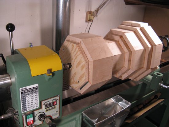
Mounted on lathe, drive end shown
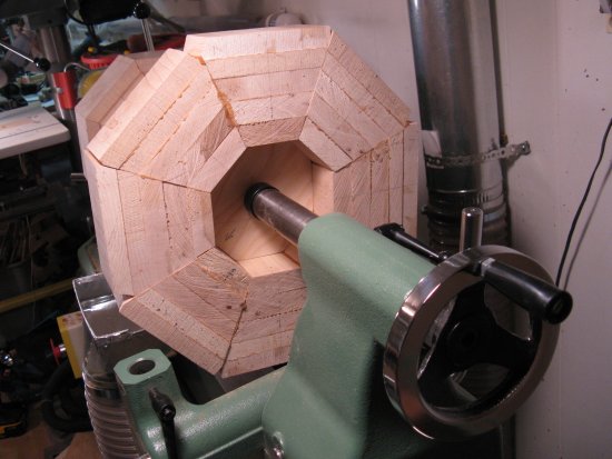
Other end
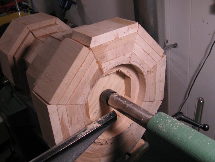
Recess has been cut
The above photos show the piece mounted between the drive spindle at the motor end and the live center on the other (tail-stock) end on the lathe. The live center can be screwed forward with the crank on the tailstock to apply pressure on the piece and push it into the drive spindle.
I was careful to position both drive spindle and live center as close to the center of the piece as possible. This ensured the least wobble.
The adjacent shot shows the recess cut out to just under a 1" depth.
I was careful to position both drive spindle and live center as close to the center of the piece as possible. This ensured the least wobble.
The adjacent shot shows the recess cut out to just under a 1" depth.
Worn plate on drive spindle end
Unfortunately using a little spindle isn't the ideal technique for spinning a huge heavy piece of wood. The spindle is only about 1" wide, so it doesn't get much grip on the wood. I found it was spinning against the wood and tearing away the soft plywood that I used for a cap.
Before the spindle chewed all the way through the plywood I pulled the piece off the lathe and added a small plate made of of oak to the top. Even so by the time I was finished, the spindle had managed to dig down a noticeable amount (aided by my regular tightening of the tailstock to keep everything secure).
Before the spindle chewed all the way through the plywood I pulled the piece off the lathe and added a small plate made of of oak to the top. Even so by the time I was finished, the spindle had managed to dig down a noticeable amount (aided by my regular tightening of the tailstock to keep everything secure).
Blank for bottom
So then the next task was to make the bottom.
To keep the grain direction consistent with the rest of the wastebasket, it needed to have the grain oriented vertically.
I started with this piece of 2" maple and after squaring the edges, cut it up into pieces just over 1" long.
To keep the grain direction consistent with the rest of the wastebasket, it needed to have the grain oriented vertically.
I started with this piece of 2" maple and after squaring the edges, cut it up into pieces just over 1" long.
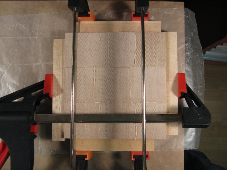
Gluing pieces for bottom
Nine pieces are laminated together here to form the piece that will become the bottom.
The funky wavy pattern in the wood is just the effect of an imperfect cut on the bandsaw (which is in fact the only kind of cut I get from my bandsaw). It wasn't a concern since it will eventually be cut off and a perfect surface wasn't required at this point.
The funky wavy pattern in the wood is just the effect of an imperfect cut on the bandsaw (which is in fact the only kind of cut I get from my bandsaw). It wasn't a concern since it will eventually be cut off and a perfect surface wasn't required at this point.
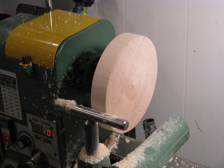
Bottom turned to correct diameter
Here the bottom has had the lathe mounting plate screwed securely to it with six stout #10 screws since it will eventually need to support the full weight of the wastebasket hanging off the end.
It was mounted to the lathe, the face was turned flat and the diameter adjusted to fit snugly into the recess cut in the bottom of the wastebasket.
It was mounted to the lathe, the face was turned flat and the diameter adjusted to fit snugly into the recess cut in the bottom of the wastebasket.
Bottom installed
Here the bottom with mounting plate has been attached to the main piece with glue and the gentle aid of some of the mallets in the background.
The "false bottom", spacer and top plate have been removed and the after a test fit, it was glued and tapped in until it sat flat on the bottom of the recess.
The "false bottom", spacer and top plate have been removed and the after a test fit, it was glued and tapped in until it sat flat on the bottom of the recess.
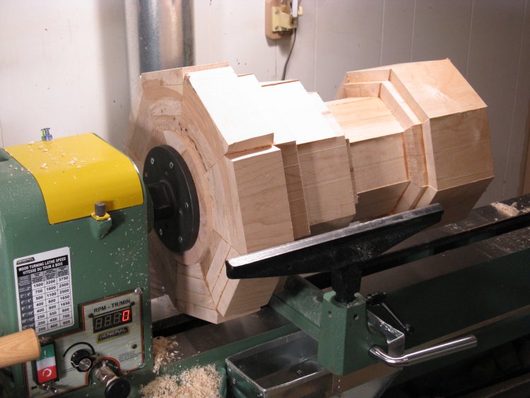
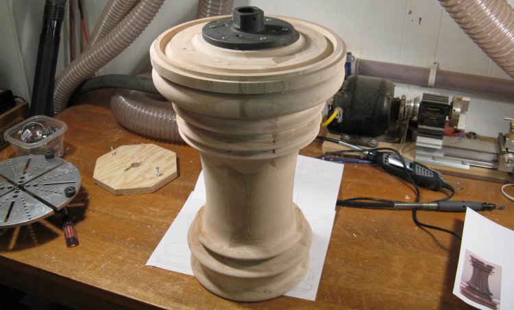
Ready to start turning
OK. Now it's ready to start turning. Really, if I had just beat the microorganisms to that log, I could have skipped the last 28 pictures.
Anyways, here it is mounted on the lathe. I'm using a 16" lathe which means the spindle is 8" above the bed. It can therefore turn something up to 16" in diameter and here there's just over an inch of clearance to the bed. The wood wouldn't hit, but it prevented the tool rest clamp from being positioned under the biggest part. That wasn't much of a problem and as you can see the tool rest mount is just beside the largest-diameter part.
After lifting the wood on and off the lathe a few times, I lugged the piece upstairs and checked the weight. It was about 35 lbs.
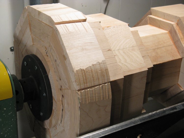
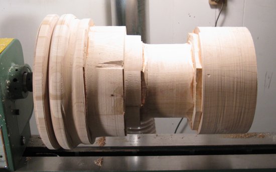
Starting the rounding
The rounding of the piece has been started. The balance wasn't too bad but it wasn't perfect either. I mostly used a fairly low speed (around 300 RPM) to do the rough cutting.

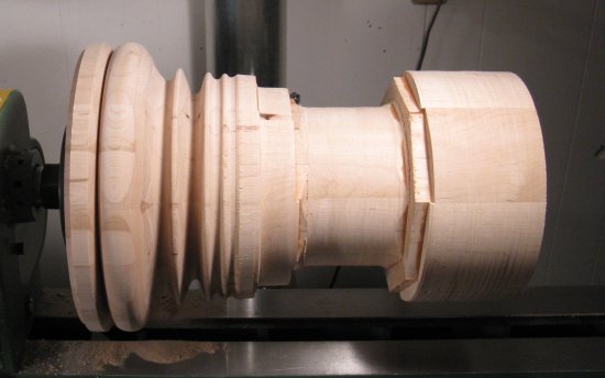
Rounding mostly done
At this stage the rounding is mostly done. It didn't actually improve the balance too much which suggested to me that the central hole was less than perfectly central.
So at this point it became obvious that I had no way to actually measure the outside diameter of this piece. I had a variety of calipers, but nothing that would stretch to 13". So I thought I'd whip up a quick pair, which would be a nice break from turning.
The first question was: What material? After some consideration I ended up using the material most favoured by expert metrologists the world over: Plywood;
The first question was: What material? After some consideration I ended up using the material most favoured by expert metrologists the world over: Plywood;
The obligatory plan
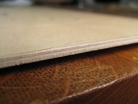
Some nice multi-layer 3mm plywood
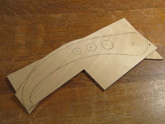
Arms marked out
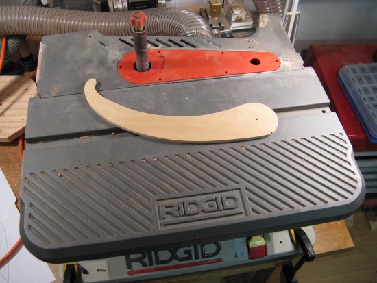
Arms sanded to shape
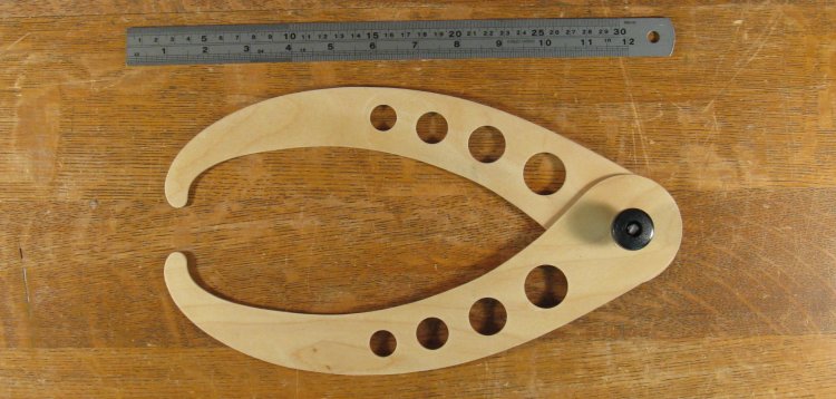
Completed calipers
The above montage shows a few shots of the construction with the finished calipers shown here.
The toughest part was arranging the hinge screw mechanism so that opening or closing the calipers didn't loosen the screw. After a number ofdismal failures valuable learning experiences, it turned out that some monofilament line on the screw threads tightened them up enough to achieve this.
The toughest part was arranging the hinge screw mechanism so that opening or closing the calipers didn't loosen the screw. After a number of
And now back to our regularly scheduled programming;
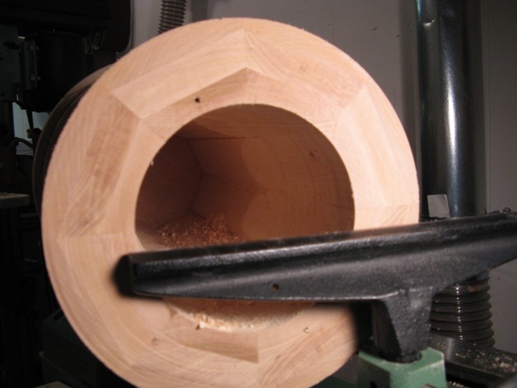
Internal rounding started
Here I've started cutting the interior to a round shape. I used a "deep hollowing tool" for this, which is handled steel tool that is 26" long with a ring-shaped cutter at the end. Unfortunately, the depth seen in this shot is as far as I could go with the cutter.
 |
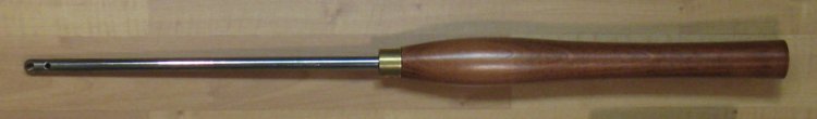
Deep hollowing tool
Hollowing tool and accompanying virtual ruler.

Gratuitous blurry-spinny lathe shot
It didn't look like there were any longer tools available locally so I contemplated making my own, which would provide another nice break from turning.
Not that there's anything wrong with turning, but when hollowing a deep hole, there are very high forces on the tool and you need to keep a death grip on the handle for control and to prevent rotation. Twenty minutes of that, and you need something easier for the jellified/cramped muscles to do for a while.
Not that there's anything wrong with turning, but when hollowing a deep hole, there are very high forces on the tool and you need to keep a death grip on the handle for control and to prevent rotation. Twenty minutes of that, and you need something easier for the jellified/cramped muscles to do for a while.

Replicated tool end
It turns out that this particular tool had a 1/2"-diameter shaft with machining at the end to accommodate a separate cutter. There was nothing preventing me from moving the cutter to something longer. I figured I'd be better of with a larger-diameter shaft, but I already had a 1/2" steel rod lying around so I used that.
This shot shows the tool (the shinier one beside the cutter) and the end of a longer rod modified to be similar.
This shot shows the tool (the shinier one beside the cutter) and the end of a longer rod modified to be similar.
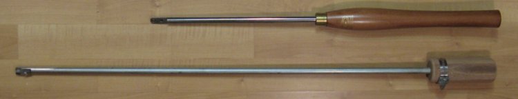
Deep and Deeper hollowing tools
Here's the existing and new tools showing the relative lengths. On the new one I made a rudimentary handle with a scrap of mahogany that I affixed with a hose clamp.
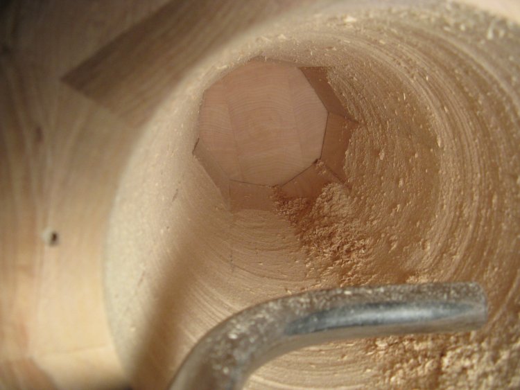
Rounding progressing
This shot shows the interior rounding having progressed a bit deeper. I finished off all the way to the bottom with the new tool. I'll note that it would certainly have benefited from a stiffer shaft, but I managed to complete the hollowing as it was if a little rougher than desired.
I then then switched the end to a different scraping cutter I had removed from a another hollowing tool. This was used to smooth off the interior surface a bit more. It still wasn't perfectly smooth, but one doesn't need to get too obsessive about surface finish on the interior of a wastebasket.
I then then switched the end to a different scraping cutter I had removed from a another hollowing tool. This was used to smooth off the interior surface a bit more. It still wasn't perfectly smooth, but one doesn't need to get too obsessive about surface finish on the interior of a wastebasket.
So then it was time to go back and finish the outside shaping;
Starting from the bottom
...and moving up
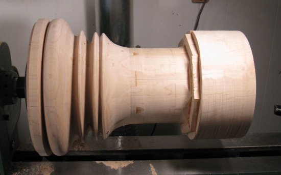
...to the top section
...and that done as well

Sanding the outside
The above shots show the shaping progressing (with liberal use of the big calipers to compare against the desired diameters).
After that, the outside was sanded using strips of sandpaper as shown here.
After that, the outside was sanded using strips of sandpaper as shown here.
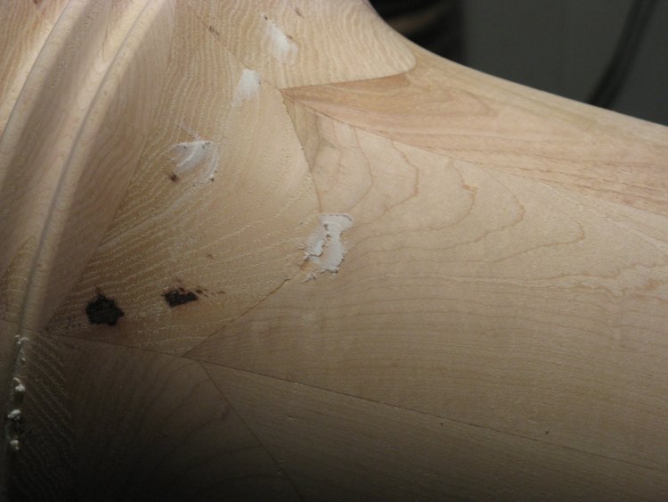
A touch of spackling
And since this piece was to be painted, there was the freedom to repair any minor problems with some filler. Since most areas were pretty small, I just used standard spackling.
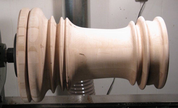
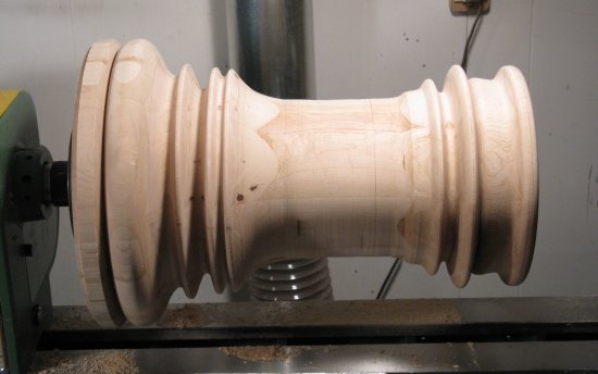
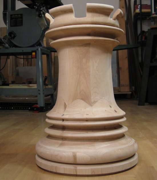
Outside turning complete
This shot shows the completed outside.
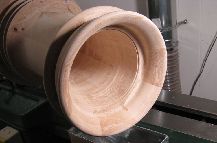
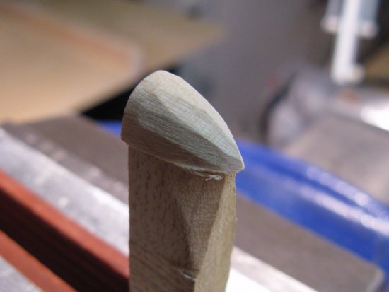
Inside top
With the outside contour established, I went back and completed the top section, which I had left when doing the inside.
Also visible in this photo is a small square-sectioned notch cut for the cover to sit in.
Also visible in this photo is a small square-sectioned notch cut for the cover to sit in.
Smoothing the bottom
Before taking it off the lathe, I smoothed off the bottom which still had the uneven profile of the glued-up pieces.
I was going to have to even off the inserted section too, but most of it was still covered by the mounting plate at this stage.
I was going to have to even off the inserted section too, but most of it was still covered by the mounting plate at this stage.
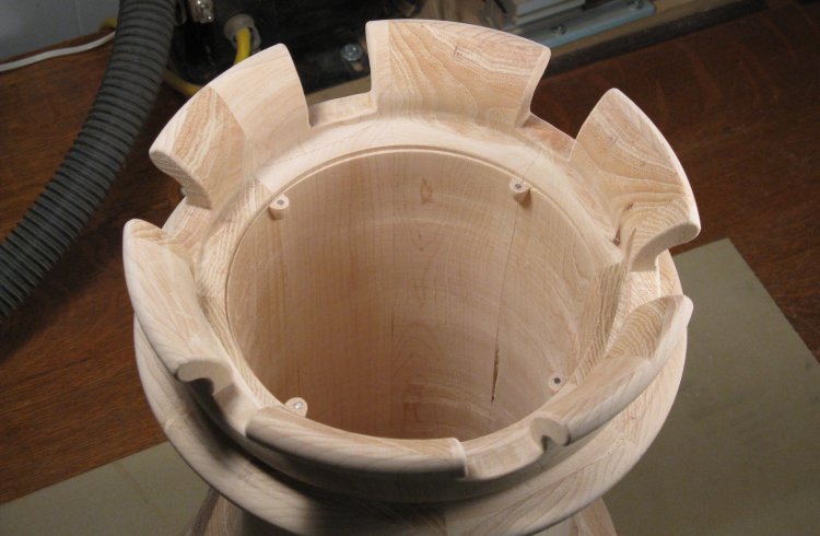
Off the lathe
This photo shows the wastebasket off the lathe. It's sort of a milestone, except then it had to go right back on to have the bottom completed.
To the right is visible a sheet of paper with a picture of the model from which this piece was made.
To the right is visible a sheet of paper with a picture of the model from which this piece was made.
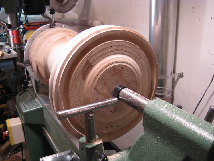
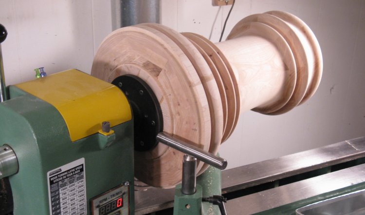
...aaand back on the lathe for bottom work
The lathe was switched over to use the large adjustable jaws. They held the top while the live center was used on the bottom again. The adjustable jaws have rubber "buttons" that grip the piece, so there would be no slipping like with the drive spindle.
As can be seen, this setup gives access to the bottom except right at the center.
As can be seen, this setup gives access to the bottom except right at the center.
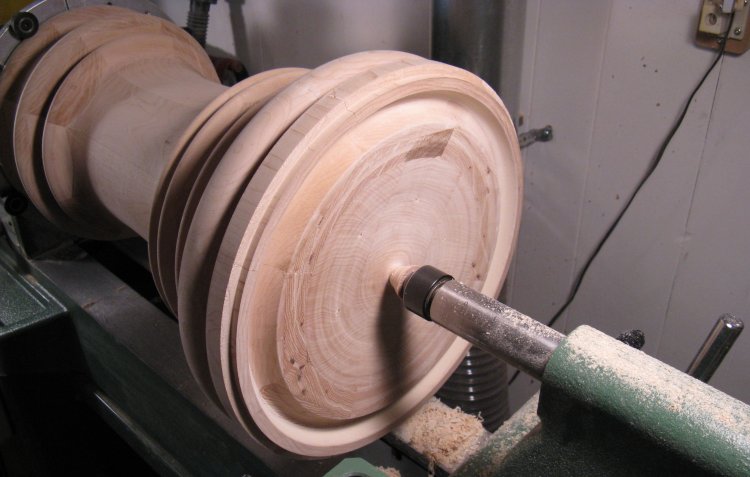
Bottom turning complete
The protruding bottom piece has been trimmed away and the center has been given a concave shape to reduce weight. There's just the little center nub remaining to be cut off and sanded smooth.
Also visible is a largish notch for fingers that was cut around the outside to aid in tilting or picking up the wastebasket.
And then back upstairs to the scale, and the unit is down to a mere 17 lbs. Which means it generated 18 pounds of sawdust, or more than half the wood I started with. Hmmm...maybe it's time to go check the dust collector bin.
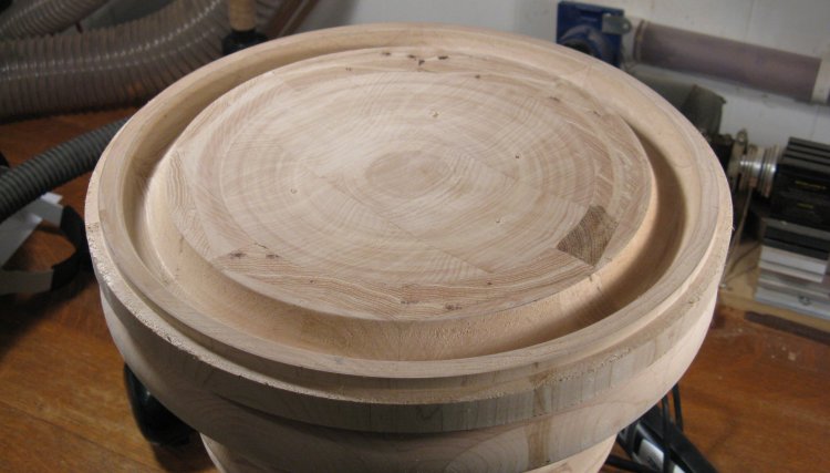
Bottom done
Here the turning nub has been cleaned off the bottom.
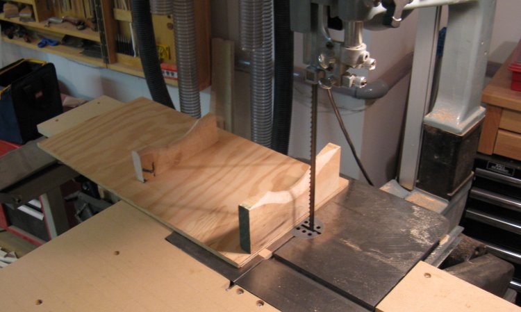
Cutting jig sitting in place
The final detail on the wastebasket is cutting the crenelations into the top. To get good consistent cuts, I decided to use the bandsaw with a jig. This shot shows the jig, which consists of a flat piece of plywood with appropriately shaped and spaced supports for the main body. The support heights are set to hold the body horizontally. The jig also includes a guide that fits into the miter slot to ensure it slides the piece straight into the blade.
A little table extension was made to support the off-table section of the jig, and the height of it was tweaked to make sure the wastebasket was exactly perpendicular to the blade.
A little table extension was made to support the off-table section of the jig, and the height of it was tweaked to make sure the wastebasket was exactly perpendicular to the blade.
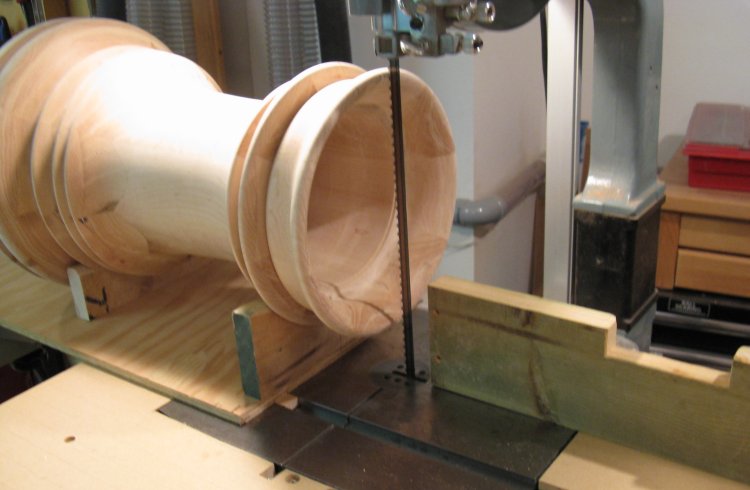
Ready to cut slots
Here the wastebasket is sitting on the jig. There was enough friction that it was held securely with no other measures. Since there are six evenly spaced slots, I just made six cuts, manually turning the body between cuts.
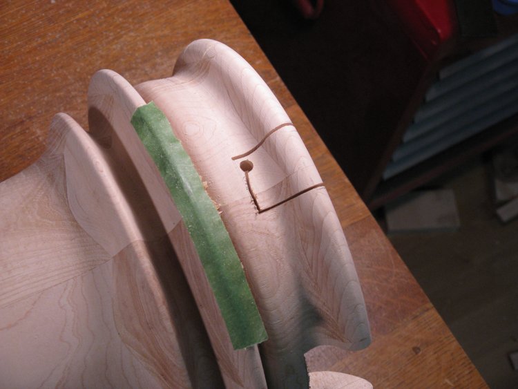
Cutting out notches
The notches were cut out using a jigsaw starting from a drilled hole. The green tape is there to prevent damage to the ridge of wood from the base of the saw.
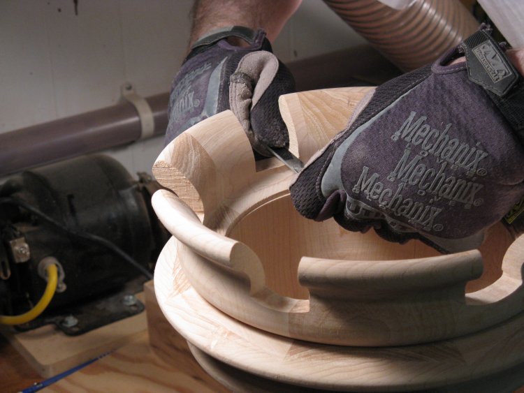
Sanding notches
This photo shows the base of a notch being shaped with an NT Dresser tool, which is a rigid piece of metal with an abrasive surface.
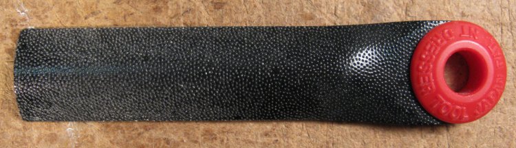
NT Dresser SR-22 close-up
The abrasive is very long-lasting and these tools are great for shaping. I have a set of 5 with different profiles. I got them at Lee Valley tools, but they don't appear to carry them any longer. A quick search suggests Japan is now the best and perhaps only place to get them. Guess I'll hold on to mine...
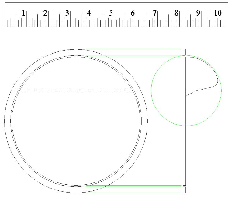
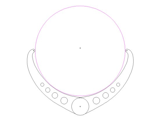
Cover plan
The next step was to make the cover. I had checked fit and sizing using cardboard prototypes when the main body was still on the lathe, so I had the dimensions established. This made sure the cover would swing far enough down inside without interference from the internal cavity.
The cover consists of a thin circular frame that sits in a notch in the body, with a hinged cover. The cover was hinged off-center to provide a larger opening, and then counterweighted on the short side to maintain balance. I made the cover pieces from 3mm Finnish Birch plywood since it is light and rigid.
The cover consists of a thin circular frame that sits in a notch in the body, with a hinged cover. The cover was hinged off-center to provide a larger opening, and then counterweighted on the short side to maintain balance. I made the cover pieces from 3mm Finnish Birch plywood since it is light and rigid.
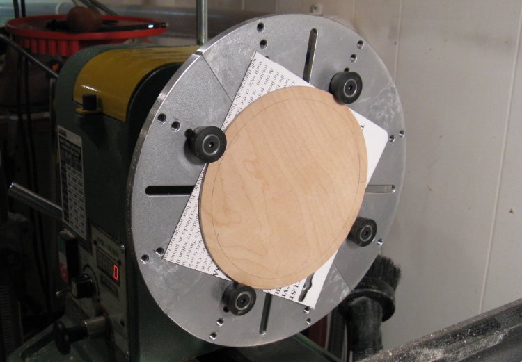
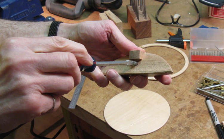
Getting ready to cut out frame center
This shot shows the piece that will become the frame after I cut away the proper center diameter. The cardboard behind the piece is there to prevent the cutting tool from contacting the metal of the jaws.
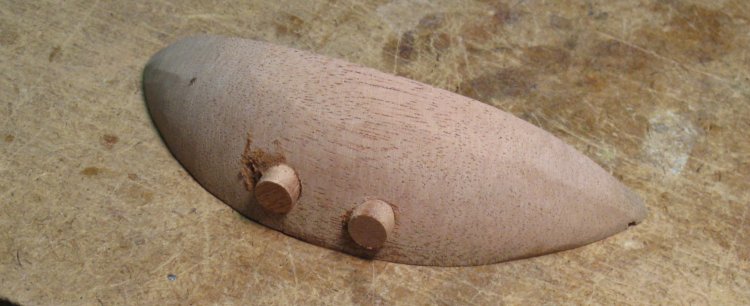
Counterweight blank
This the blank I started with for the counterweight. I didn't find any especially heavy woods around the shop (that I wanted to sacrifice for a counterweight anyway) so I just used the piece of mahogany shown here which so far has been cut and sanded to the round contour of the cover.
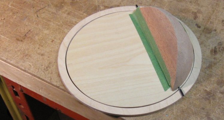
Counterweight shaped
Here the counterweight has been shaped to ensure it fits through the frame when the front of the cover is swiveled down.
Plugged holes after extra weight added
As I had half-expected, the counterweight wasn't quite adequate to balance the cover. I added some extra weight by drilling a couple holes and adding to each a 3/4" length of a large steel bolt. In this shot, those holes have been plugged and some glue/sawdust filler used to fill some gaps.
Adding adjustable weight
And then since the balance was pretty sensitive and I didn't know how much the paint would throw it off, I added an adjustable counterweight by drilling and tapping a hole for a short length of 5/16" bolt.
I also added a little shelf to the "top" of the counter weight (which will in fact be the bottom when it is mounted in the wastebasket) in case I needed to add a weight to help close the cover. In the end that went unused.
I also added a little shelf to the "top" of the counter weight (which will in fact be the bottom when it is mounted in the wastebasket) in case I needed to add a weight to help close the cover. In the end that went unused.
Assembling cover
Here the counterweight is being glued to the cover. There is a notch on the bottom side of the counterweight to house a hinge rod, as well as short sections of brass tubing at the edges to ensure a good fit of the rod.
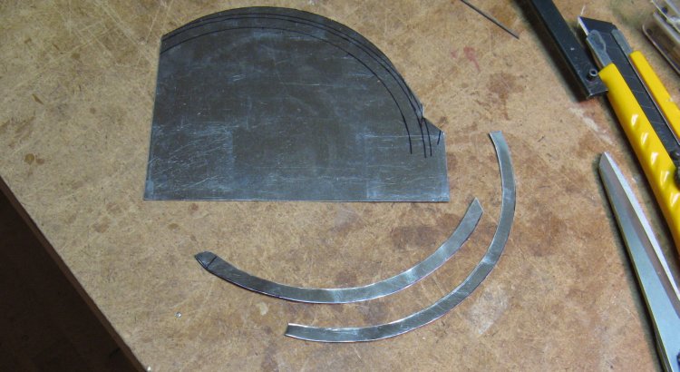
Cutting steel for frame
I decided that I would use magnets to hold the frame and cover in place so it could be easily removed for emptying. In order to eliminate any particular alignment of the cover to the body, I wanted to have the cover frame magnetic all around, so I used some 10 mil steel sheet to make arcs of material to be glued in place.
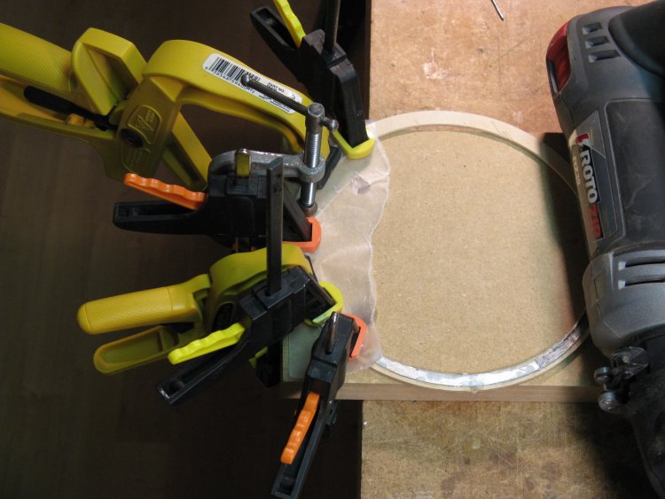
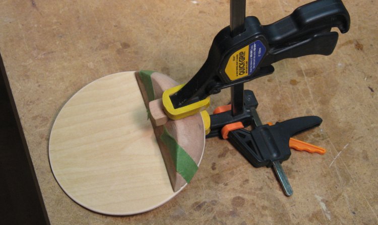
Gluing on a ring
One of the metal pieces is being glued on in this shot. Each piece was trimmed to fit and then epoxied in place. The large number of clamps is to ensure the metal sits flat along its length while the glue sets.
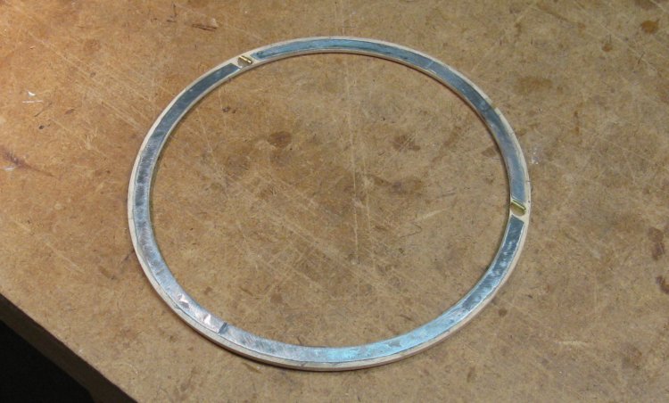
Cover frame complete
This shows the bottom side of the cover frame. In addition to the steel pieces, short sections of brass tubing for the hinge have been epoxied in place.

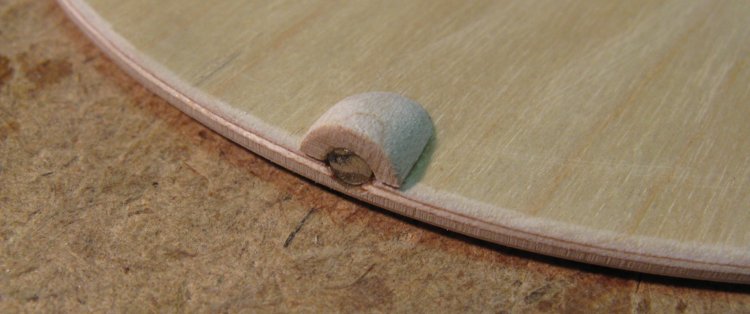
Hinge close-up
This shows a close-up of one of the hinges. A steel rod is used for the hinge and the cover is spaced from the frame with some small washers.
Cover magnet
To ensure that the cover closed level, a small rare-earth magnet was added to the front of the cover. The magnet centers on edge of the steel on the frame.
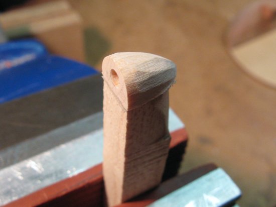
Front of frame holder
Rear of frame holder
Holders in place
The above photos show one of the small pieces that will fit into the top of the wastebasket and hold magnets to secure the cover. In this shot, they have been roughly sanded to shape on a belt sander and have yet to be hand-sanded smooth.
And to the right is the wastebasket with the four magnetic holders in place. They sit just below the ridge that holds the cover frame.
And to the right is the wastebasket with the four magnetic holders in place. They sit just below the ridge that holds the cover frame.
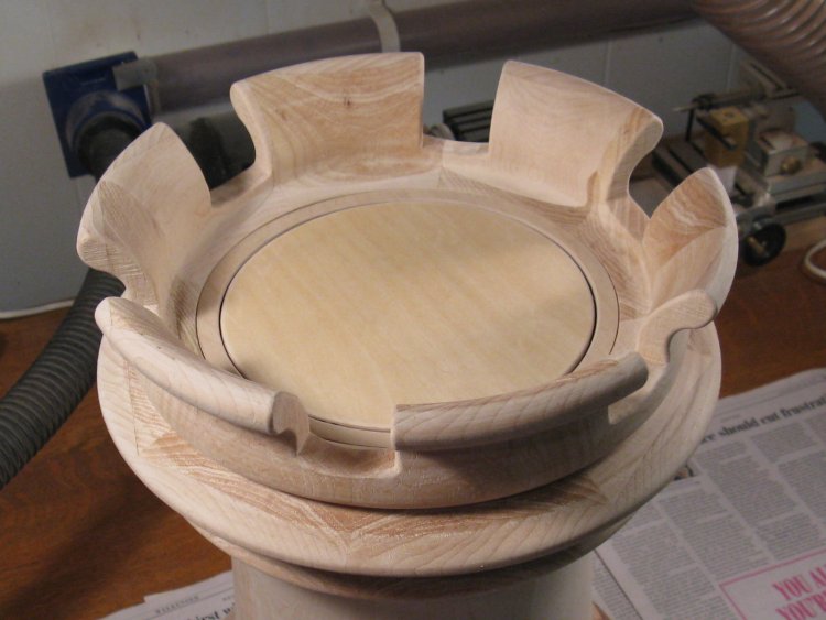
Cover in place
Here cover and frame are in place.
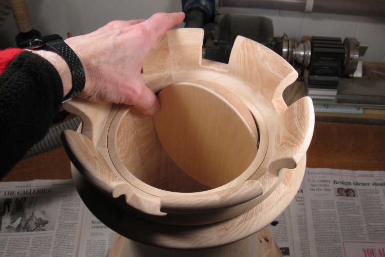
Cover open
Cover open with counterweight sticking up.
Complete
A cat's-eye-height photo of the completed unit.
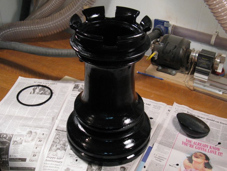
First coat of paint
This shot shows the first coat of paint, still wet. It ended up with about four more coats as I tried to achieve the finish I was looking for.
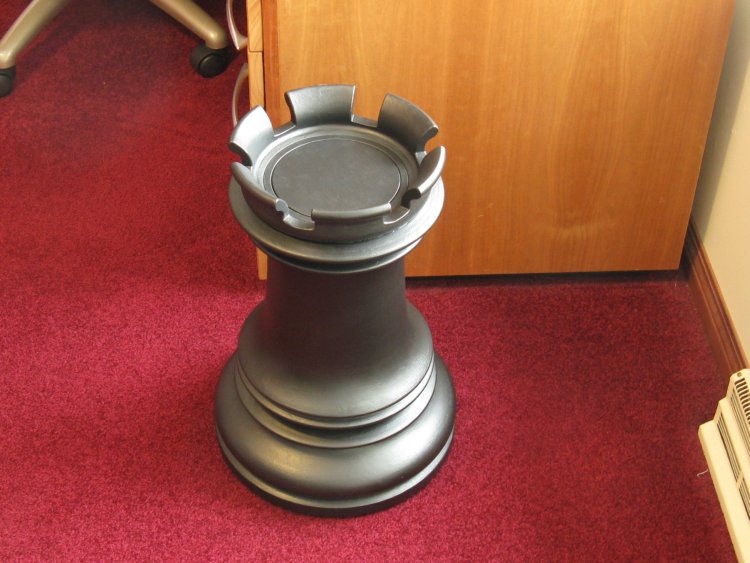
Completed and in place
The completed unit in place.


