Details
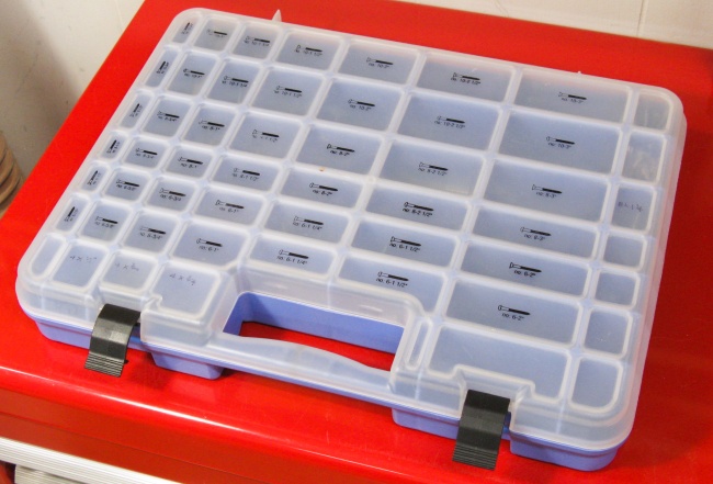
I have a convenient
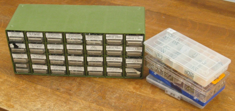
lidded plastic case in my shop that holds a fairly comprehensive selection of wood screws but when I run out of a particular type of screw or need something different I have to go dig up the appropriate part from one of several locations in the utility room. A shelf holding plastic boxes of screws is one of those places, but finding the appropriate one involves digging through not-very-organized stacks of irregularly-sized screw boxes. I've had a low-level desire for some time to make that more convenient and finally got around to it.
I decided a set of drawers would be best, with screws arranged by type, size and length. I found some almost-appropriate drawers commercially available but thought I could get something that hit a bit closer to the bulls-eye if I made them myself. The original thought had been to make actual drawers with compartments somehow fabricated in them. However I was able to find the same nice cases with multi-size-compartments as my shop screw collection uses, and decided to just use the bottoms of those cases as the compartments. So instead of proper drawers I ended up making trays to fit the case bottoms. That had to be a whole bunch simpler than trying to somehow fabricate dozens of compartments in regular drawers.
The reasonably generous storage capacity of these drawers also allowed me to integrate the contents of another drawer set of screws and bolts as well as five smaller plastic cases of various hardware selections, reducing the utility room clutter by perhaps 0.025%.

2D plans for those who like isometric projections
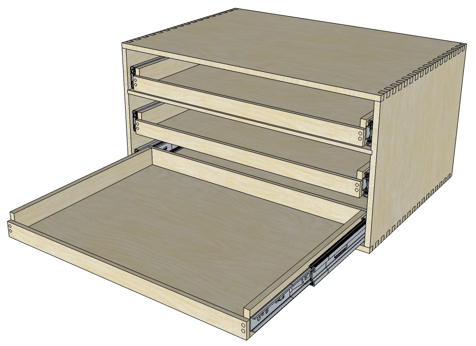
And the 3D view for those with, like, eyes
The Problem
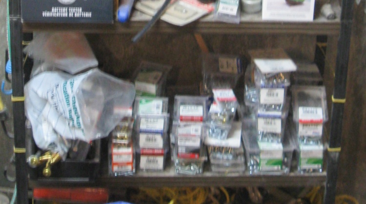
The original screw shelf
This is the original wood-screw shelf with a plethora of boxes in a variety of sizes. They are irritatingly crowded and stacked annoyingly high and they're not even in focus. Clearly something needs to change.
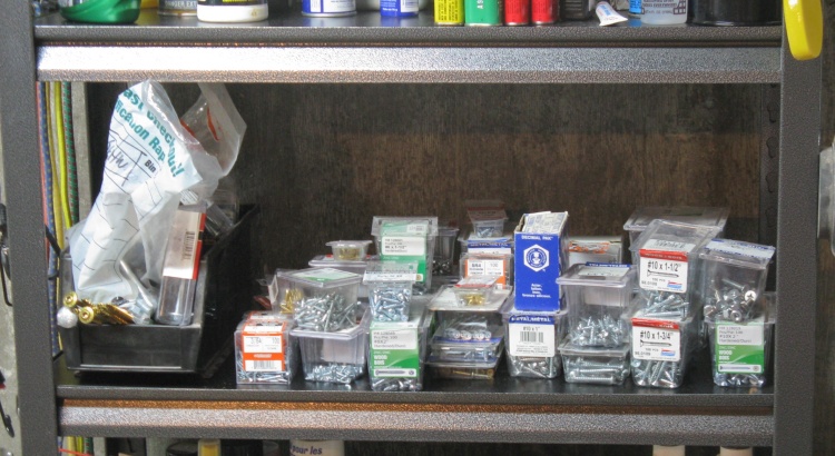
Same screws on larger shelf
A minor improvement was to replace the crappy old shelves with some less-crappy new shelves in a slightly larger size (12 x 30" vs. the old 10 x 24"). That gave the screws 50% more space and also made a marked improvement to the focus.
But that was just setting the stage, so to speak, for the screw drawers.
Some extras to be included
In addition to the shelf of wood screws, I have various other screw selections accumulated over the years (intentionally or otherwise) which I wanted to consolidate. The plan was to include these six cases of hardware in the new solution.
The Solution: Cabinet Fabrication
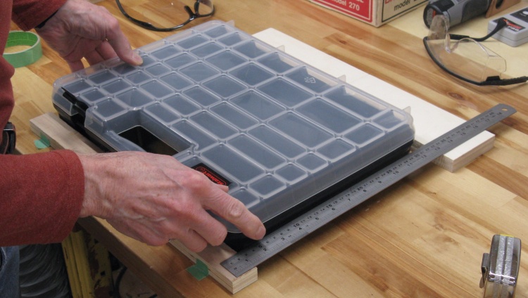
Checking the fit of a new case
This shows one of the plastic cases complete with cover, the latter's fate of which is to be unceremoniously torn off and discarded.
The outside of the plastic case has various tapers and protuberances so in this shot I'm just verifying that my measurements of the irregular shape were accurate. I rather wanted to avoid making a cabinet into which the cases failed to fit. The measurements were fine, thanks for asking.
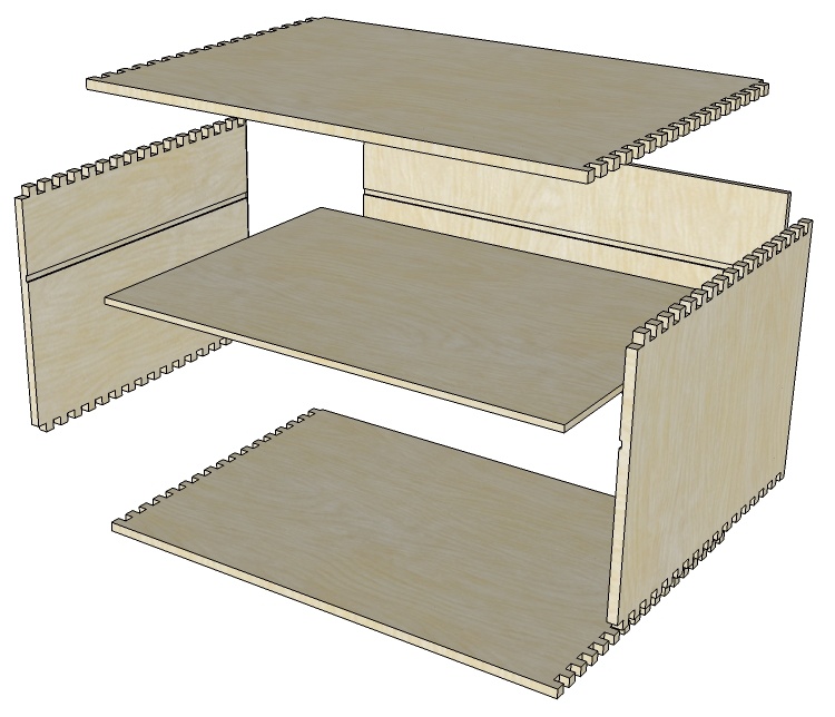
The case components in Explodovision
tm
So I don't suppose case construction gets a whole lot simpler than this one. It consists of:
- Four finger-jointed sides that form a rectangular cabinet, made from 3/8" plywood;
- A back and a single inner support to help with side wall rigidity, made from 1/4" plywood.
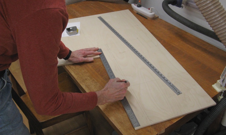
Marking up some on-hand 3/8" plywood
I happened to have most of a half-sheet* of 3/8" Baltic birch plywood on hand and that would be enough for all the 3/8" parts of the drawer set.
I started by marking out the pieces.
* A full sheet being an unusual 60x60" due to its Balticity.

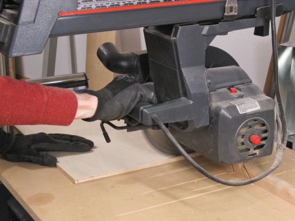
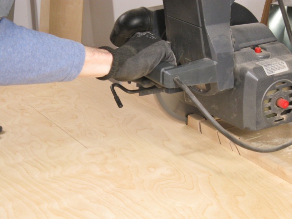
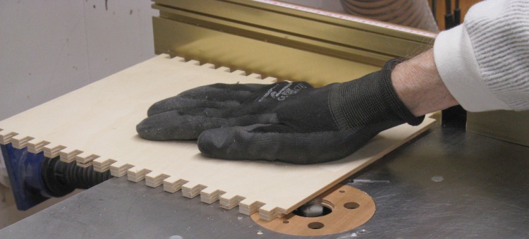
Chopping up the plywood
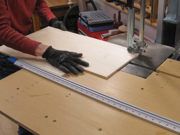
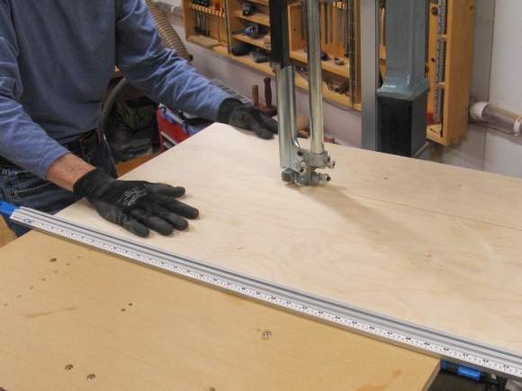
Unfortunately the wood dimensions (and truth be told, my planning) didn't let me use either the bandsaw or the radial arm saw for the initial cuts. However I had extra space between the pieces so I just used a cordless circular saw to make hand-held cuts outside the lines for eventual trimming with more-accurate machines.
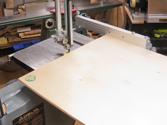
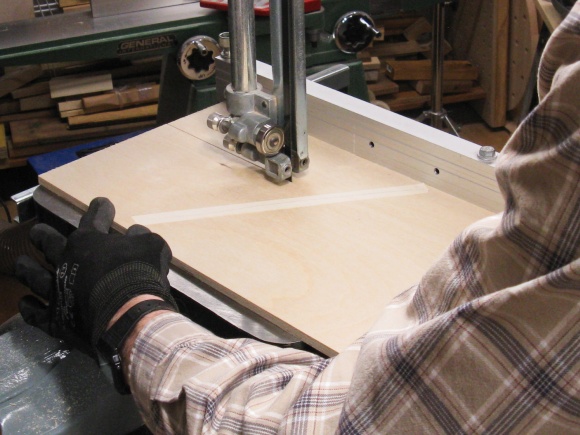
So then I fired up the more-accurate machines; As usual the bandsaw was used to cut parallel with the outside grain and the radial arm saw was used to cut across the grain.
And I'll just note here that knitted shirts hold a lot of sawdust and don't give it up easily.
Getting to the right-sized pieces with the bandsaw
...and the radial arm saw
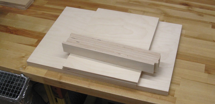
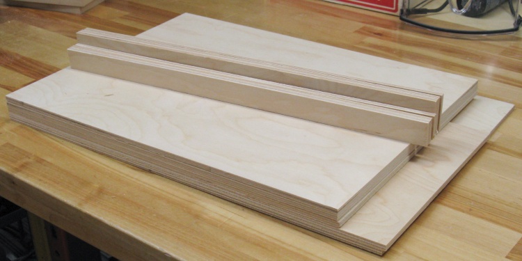
All the 3/8" bits needed; case pieces and drawer sides
In addition to the four case walls, the 3/8" plywood was used for the drawer sides. I cut out six of those and the full set of 3/8" parts are shown here.
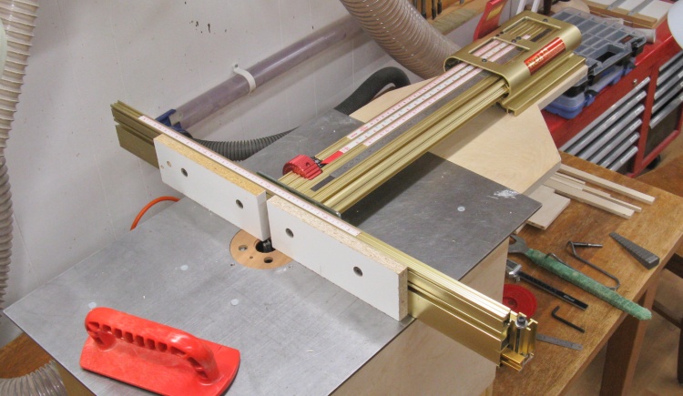
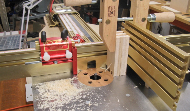
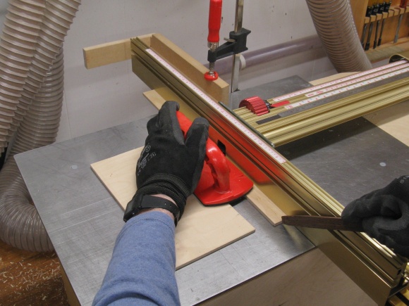
The "LS Positioner" deployed on the router table
The next steps required routing.
To the router table was mounted the extension supporting the LS Positioner which is essentially a movable fence equipped with an accurate positioning scale.
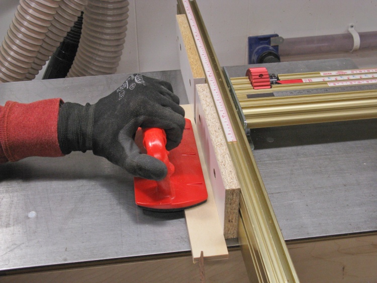
Routing a slot into a drawer side to fit the bottom
First up was routing a rabbet (corner cut-out) along the bottom edges of the tray side walls. This would let the walls overlap the 1/4"-thick plywood that formed the bottom of the tray.
Like that
Some small joint-test pieces routed out
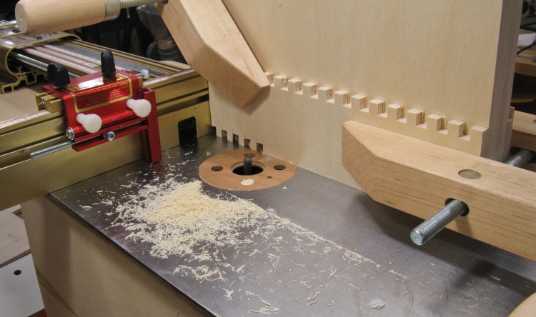
Then the rather more-involved cutting of the box joints;
I started by doing a small test joint with only three fingers and three notches. A 3/8" bit is used to cut 3/8"-wide notches and the fence is moved 3/4" between cuts to form 3/8" fingers as well.
Due to the annoying tendency of reality to be, well, real, things tend not to work out with the same glorious perfection as the pure mathematical model. I started by making joints on one end of the test pieces using my pure glorious mathematical model but they ended up being too tight and wouldn't easily engage. Yup - it's reality or a darn good simulation. So then I adjusted the technique and cut the second end as shown in this shot, which worked out better.
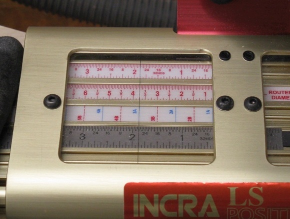
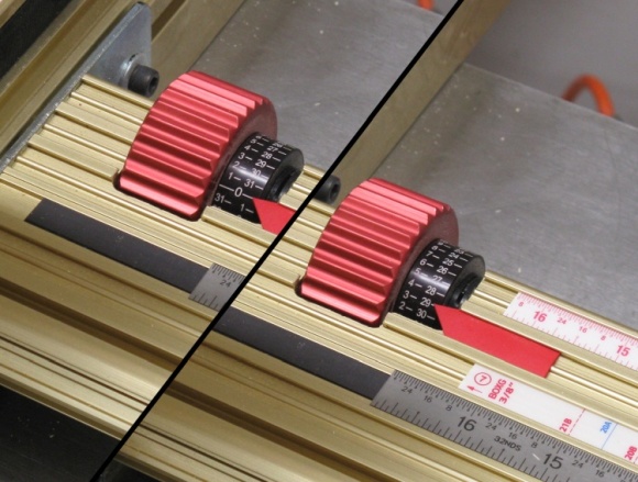
The photos below show some details of the positioner. The left shot shows a number of measurement scales but in this case I'm using the second one up which is specifically made for 3/8" box joints with a 3/8" cutter. A cut is made after aligning one of the numbered blue lines with the hairline cursor.
The right shot shows the vernier control. Since the default settings produced a too-tight joint, for each gap I made a first cut at the zero setting and then a second cut with the fence adjusted 0.003" further to widen the gaps a bit (although I ultimately used 0.004" on the actual case joints).
A cut made at each of the blue lines
Making a second cut to widen the slot a bit
The case pieces clamped to the router
This photo shows the four case walls all mounted to the positioner sled so they can all be routed at the same time. There are also scrap boards on the front and back of the stack to prevent splintering of the good pieces as the bit enters and exits the stack of wood.
Sliding the sled along to make a cut
This is more of an action shot (yes, difficult to tell from a still) where I'm pushing the sled forward so the wood passes over the router bit. That was done twice for each slot, of which there were 17 in these joints.
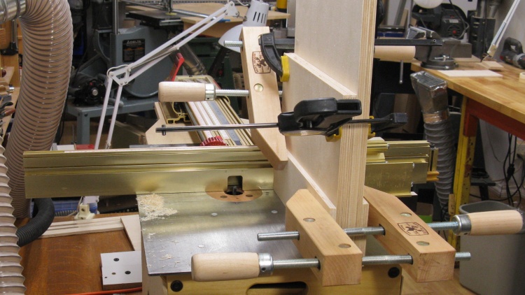
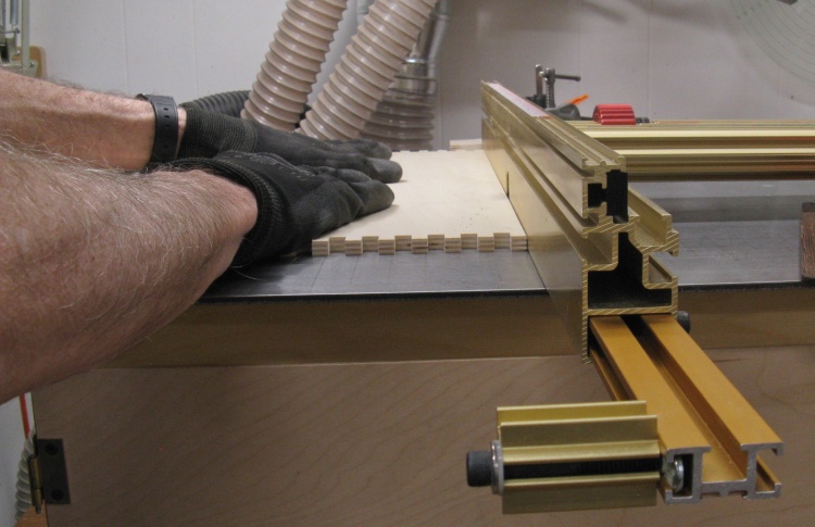
Aligning the boards to cut the second end
After the full 17 slots were cut in one end, the case sides were removed from the router table and rearranged so the other ends were aligned. Here I'm clamping the four boards together so they are even along the bottom and side.
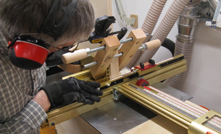
Part way through cutting the second ends
Here we are part way through cutting the second set of joints.
Note that since there are an equal number of fingers and slots that means that there is a finger at one end with a slot at the other on any given piece. The implication of that is that I can cut both sides of the joint at the same time and then reverse one of the sides so its end finger aligns with the end slot of the mating piece, so that's a nice time-saver.
The be-knobbed red assembly in this photo is a physical stop that limits the travel of the sled.
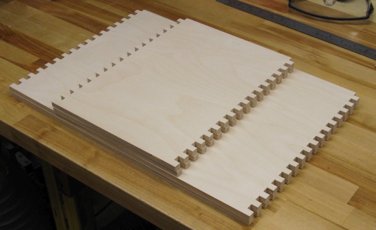
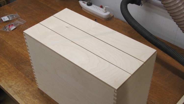
Case side joints done
This shows the four case sides with the joints done.

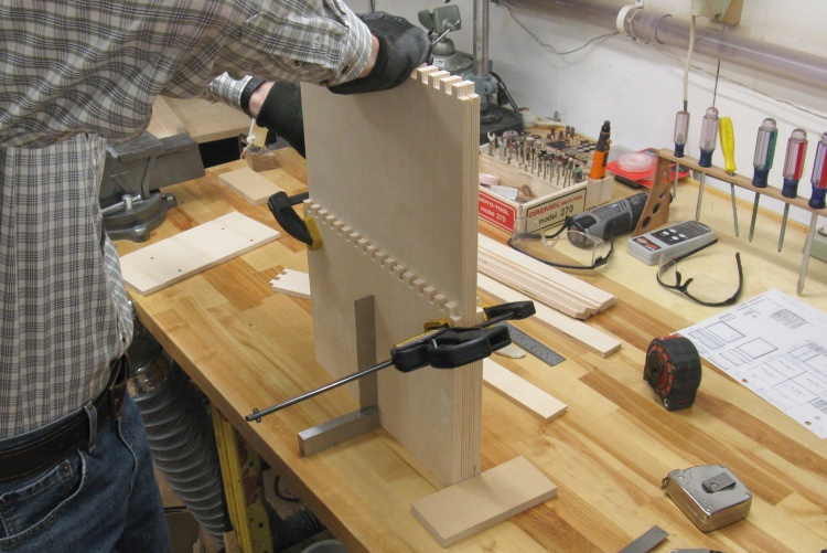
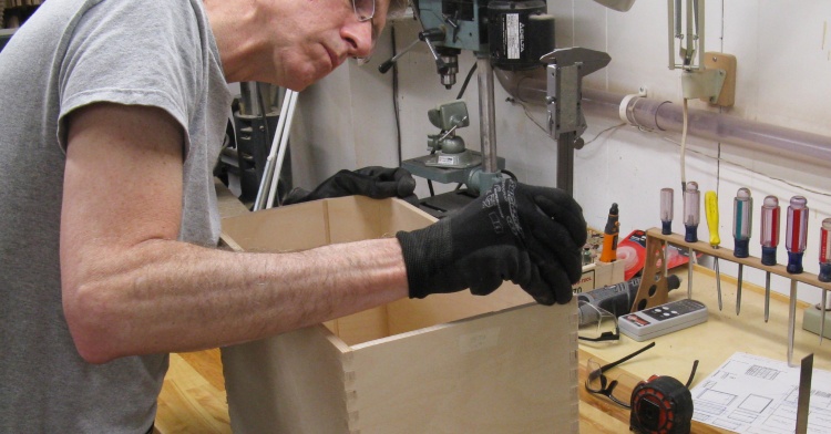
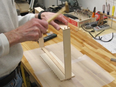
Doing a test assembly of the case
The joints were still pretty tight so I did a quick pass of a file over the finger edges to remove any protruding wood fibers, and then tapped the pieces together as shown here.
I had gone for a blood test earlier in the day, hence the bandage and the anomalous short sleeves in the winter; the shop is around 19 Deg so I like to wear long sleeves.
Making sure walls are even
Ideally the first joint slot is exactly equal in width to a finger and everything then aligns perfectly. My first slots were...imperfect. The upshot was that there was about 0.04" offset between the top/bottom and the sides.
I marked that, did a bit of jointer work to even things out and in this shot reassembled the case and I'm rechecking the offset (small enough not to worry about despite my severe expression).
Routing a rabbet for the case back
With all the walls flush it was safe to rout rabbets in the inside corners to accommodate the case back. This photo shows the top being routed.
I've set up stops to make sure I don't blow through the ends (since otherwise I'd have to actually remember for several minutes - hardly realistic).
Tray Fabrication
Next up was the trays; I would need three of them, all the same size.
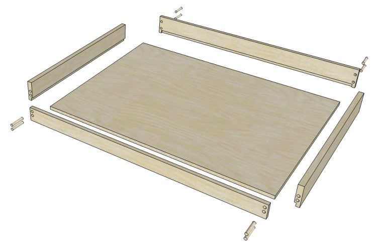
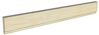
An exploded view of the tray
This illustration shows the pieces I'll need. The sides are made from 3/8" plywood and have already been fabricated, so that leaves the bottom, front and back which will be made from 1/4" plywood. Pairs of 3/16" dowel pins will help hold the walls together.
I started with a couple of 1/3 sheets of 1/4" plywood. Fortunately the part layout permitted use of the bandsaw and radial arm saws directly with no preliminary cutting. As usual, with-grain cuts were made with the bandsaw first and then pieces were cut to length on the radial arm saw.
Ripping the 1/4" plywood
...and crosscutting for variety
All the 1/4" bits cut to size
A bit later and I had all the pieces cut to size.
In addition to the tray pieces, the case needed a back and a center support which were also 1/4" material so they are part of this pile as well.
The drawer walls needed rabbets in the lower edge to house the bottom panel. On the side walls, these could go end-to-end but for the front and back they need to stop before the ends. I set up stops on the router, cut the rabbets while stopping short of the ends and then manually squared up the ends of the rabbets using a utility knife.
Routing a bottom rabbet on drawer back
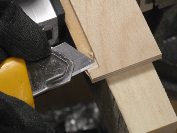
Squaring off the rabbet corners
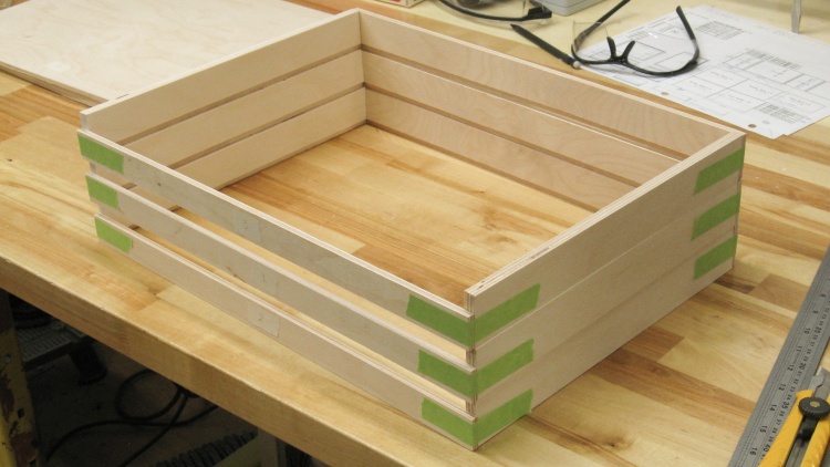
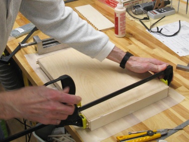
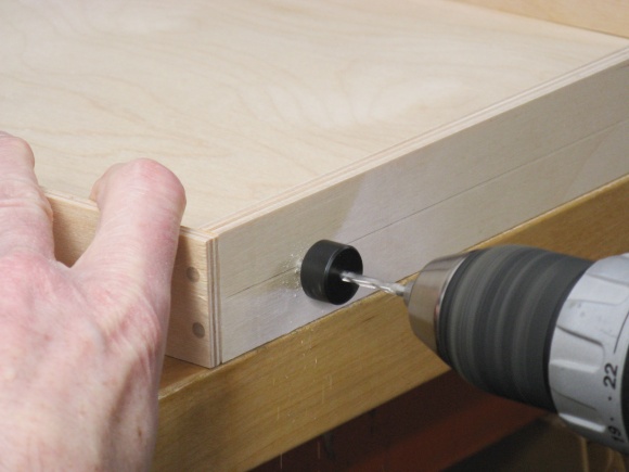
Trays taped together for drilling
Here's the three sets of tray walls, taped together and ready to have the dowel holes drilled.
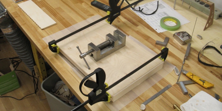
Drilling into the end of a narrow foot-long floppy frame was going to be a bit tricky. I decided I needed some good support for the frame and what turned out to be ideal was just clamping the dry-assembled case to the drill press table. My table is mounted on a cross vise so I could just turn the cranks to precisely set the position under the drill bit.
I used three or four position settings which let me drill the eight holes in the four corners.
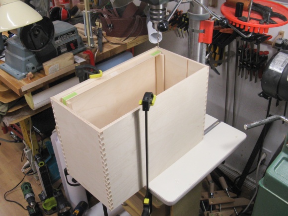
The case was used as a drill jig
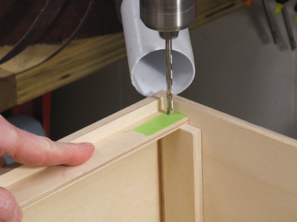
Drilling a dowel hole
I just used a Rona-bought 3/16"-diameter dowel (which turned out to be reasonably accurate in size and also round, two parameters that can one not necessarily rely on with commercial dowel). It was chopped into 1" lengths on the bandsaw and then tapped into the holes as I drilled them to keep everything in position.
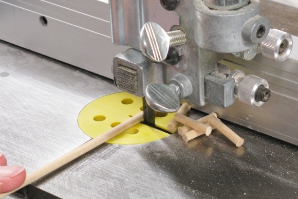
Chopping up the 3/16" dowel
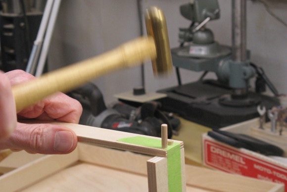
Installing dowels in drilled holes
Once the tray hole drilling was complete, I pulled all the trays apart again and extracted the pins because then it was time to put them together for real. That was simply a matter of putting them back together, but with glue this time. Once a frame was together the bottom was glued in as well and clamps added.
Adding glue to tray side
Installing pins
Adding clamps
First tray glued & clamped
This is the first tray, clamped and drying.
The weighty stainless steel vise helps ensure the bottom panel is fully inserted in the tray sides.
Once the glue was dry, the extra length of the pins was just sanded flush using the belt sander.

Sanding pins flush
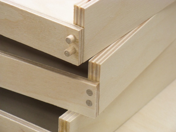
Like that
Assembly Prep
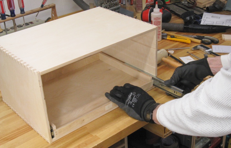
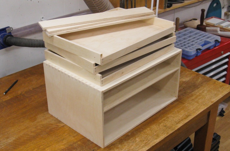
Trial assembly
This is a step I forgot to do earlier and now I get to pay for it.
The missed step was to check that the tray & slides fit correctly into the cabinet. So I didn't do that check until now after the trays were already glued together. And things were...tight. Real tight. I was going to have to find 1/16" of width somewhere. I decided that should come mostly out of the case walls.
This shot actually shows the post-thinning recheck of fit which went a lot better.
Thinning the sides
I just routed off about 0.03" from each of the side walls where the slides were mounted (and jointed another 0.01" from the drawer sides for good measure). This shot shows one of the sides being routed.
Everything fit together nicely after that.
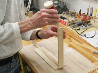
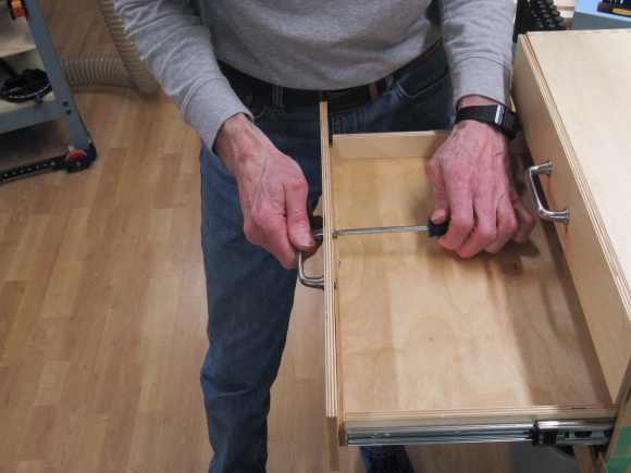
After that debacle, I made sure to fully assemble everything on the cabinet to check for fit. So that meant it was time to mount the slides. These shots show a couple of the steps.
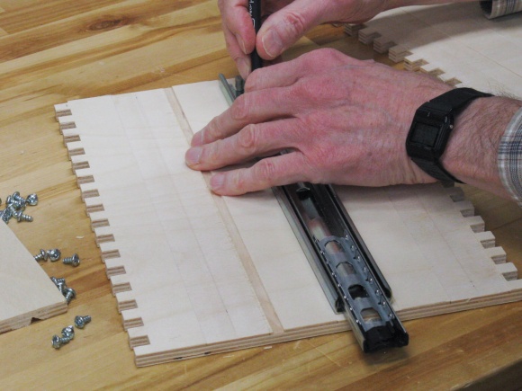
Marking slide holes on cabinet sides
Drilling for slide screws in tray
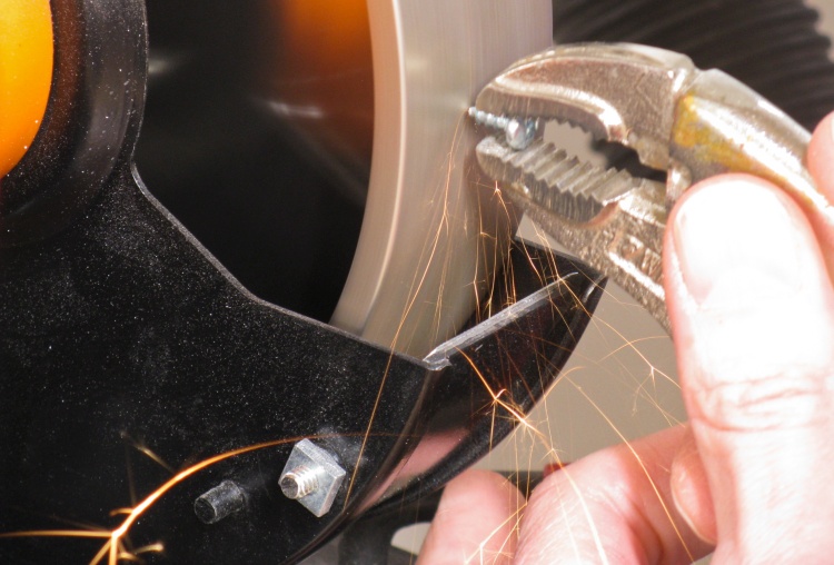
Shortening a screw
The slides came with 5/8" screws which were much too long for my 3/8" case sides. Even 3/8" screws were iffy (especially with the thinned cabinet sides) so I ground off around 1/16" of the pointy ends of the 3/8" screws I was planning to use.
This nice sparky shot shows one of the screws being ground down on my snazzy cubic boron nitride grinder wheel.
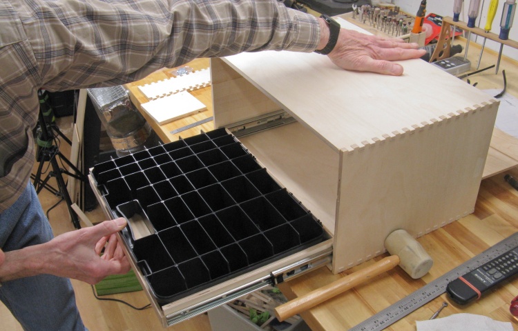
Test fit
This photo shows the lowest tray in place, complete with the compartment insert.
I finished installing the slides and checked the other two trays as well; fit was good.
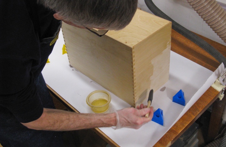
Then it was finally time to glue the case together. I did two adjacent joints at once and the other two when the first were dry. This shows glue being brushed onto a joint and then tapping whacking things together with the rubber mallet.
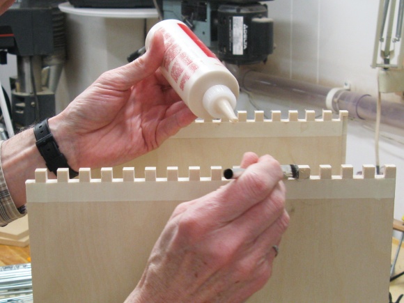
Adding glue to case joints
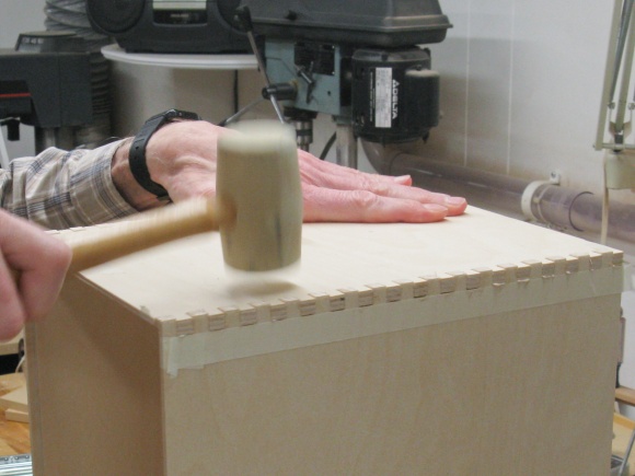
Installing case side
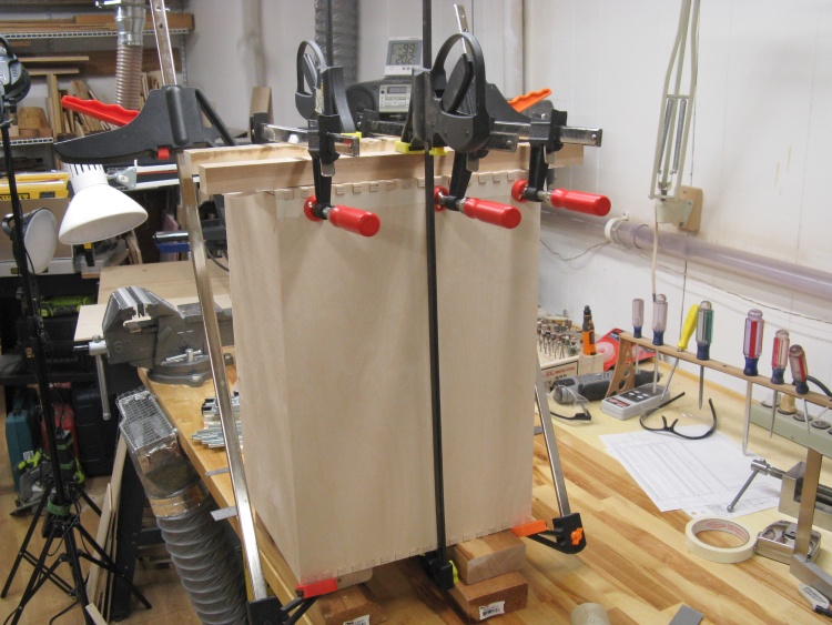
Case glued and clamped
The case got a few clamps to make sure things were tight and square while the joints dried.

Sanding joints flush
The fingers of the joints were made a bit long so in this shot I'm sanding them flush with the surrounding surfaces.
Tray Fronts
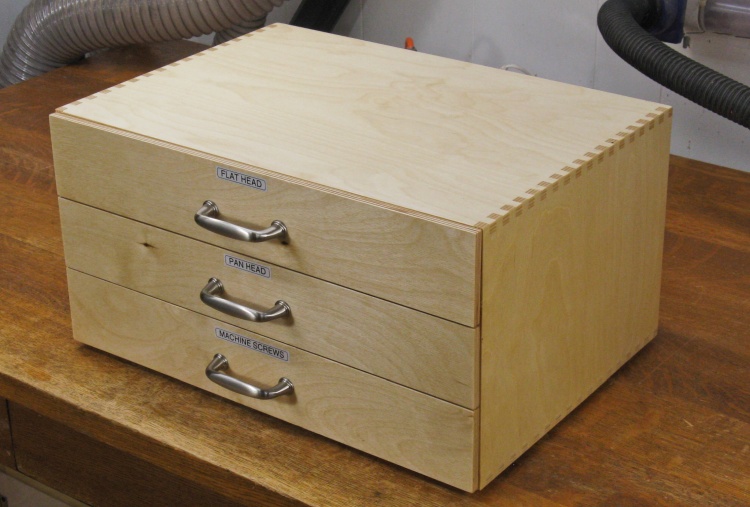
So the case looked rather...industrial with the tray edges and inserts visible. I had originally thought full fronts would make access to the parts more difficult but when I checked during my test fit, that didn't seem to be the case. There was some draw to having this case look like the previous case I'd made so I "pivoted" (a popular corporate weasel word these days for changing direction) and looked at adding similar fronts and handles.
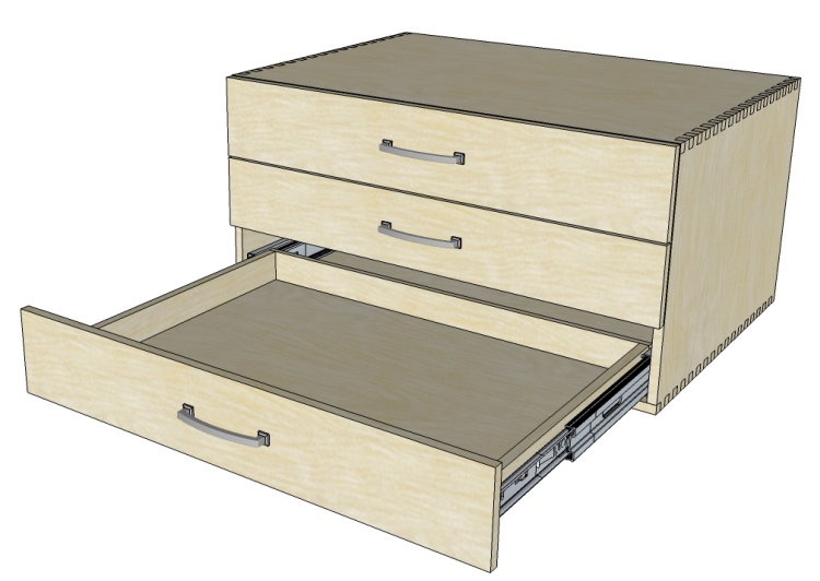
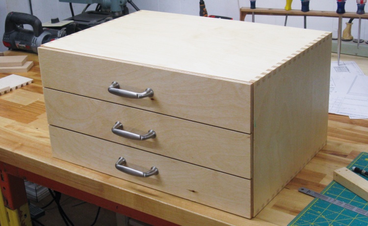
Revised look with tray fronts added
The more-finished looking case with tray fronts and pulls.
I'd been pleased that there had been enough 3/8" plywood in the shop to make the screw drawers but those pretty much sopped up all of it. So then it was back to Windsor Plywood for another piece for the tray fronts. The fronts were pretty simple - I just cut a corner out of the sheet and chopped that into three pieces. A bit of edge trimming and they were mostly done.
Chopping up a new 3/8" sheet
Cutting out tray fronts
The three tray fronts cut to size
Here the fronts are positioned on the case to check sizing. I'll wait until after finishing to add handle holes.
Finishing
All the wood bits ready to go
This is the complete pile of parts ready for finishing.
Starting on the varnishing
I used my standard Fast-Dry* Polyurethane varnish. In this shot I'm applying the first coat with a foam brush.
*It's not.
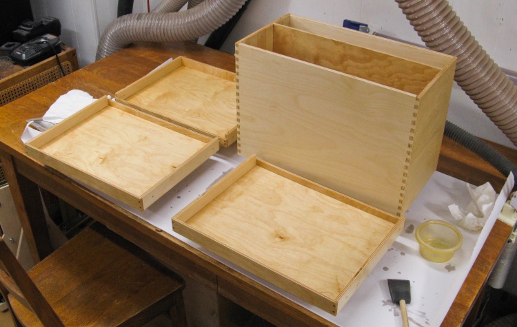
First coat of varnish in place
The first coat of varnish has been applied to all the pieces. The tray fronts had to do their drying elsewhere since I ran out of room on the oak table.
I used two coats of varnish.
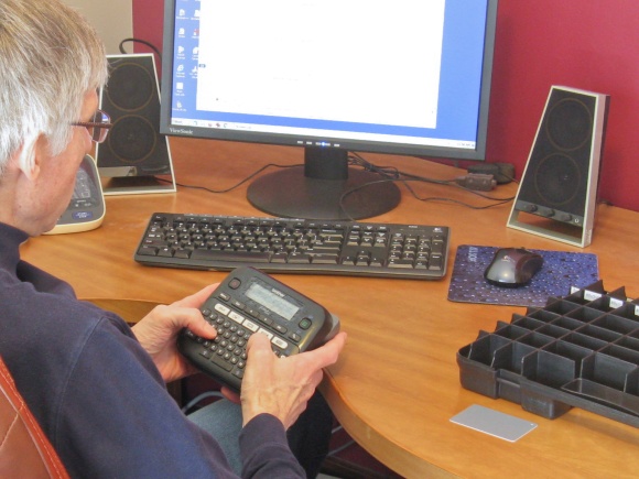
Then while the varnish was drying I had time to start labelling the tray inserts. I had previously allocated which parts went into which drawer and compartment, clearly laid out in the unreadable spreadsheet on the monitor. I used a handheld label maker to print out strips of self-adhesive labels that I then cut into pieces and stuck to the appropriate compartment.
Printing up labels
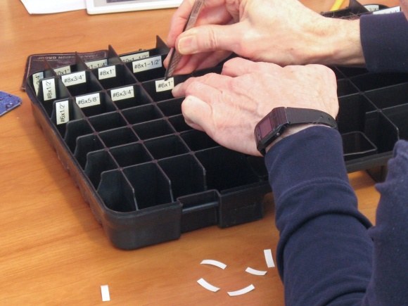
Sticking labels in place
Final Assembly
I started putting the case together after the varnish had completely dried. The slides were installed first which just involved screwing them down into the already-existing holes on both the case and tray sides.
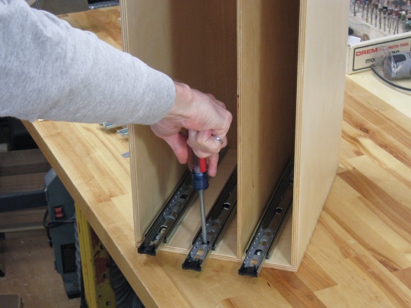
Screwing a slide into the case
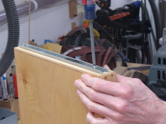
...and the matching piece on a tray side
Installing the front panels was a bit tricky since mounting holes needed to match between the tray fronts and the front panels. I ended up using thick double-sided tape (carpet mounting tape) to stick the front panels to the trays in the proper positions. That let me re-open the drawer to mark the hole locations as in the left photo. After drilling not-quite-through pilot holes in the front panels, I screwed them to the tray front from the inside and then installed the handle.
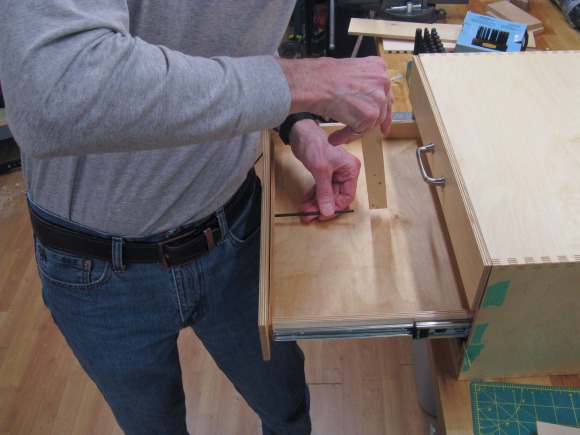
Marking front panel holes
Installing the handle
The screw case all together
This shot shows the case with all the trays installed. It just needs the screw-holding inserts added.
I thought it would make sense to try to use the same handles as on the junk drawers and after digging through some old receipts I managed to track them down.
Note to Future Russ: In case I build another matching set, the pulls are Richelieu 877A, 3" Brushed Nickel, BP876195. And sorry I didn't exercise more.

Filling one of the inserts
Of course I needed to fill the inserts first. This shot shows me working on the insert holding the machine screws.
Emptied packages of wood screws attest to the completion of the other two inserts.
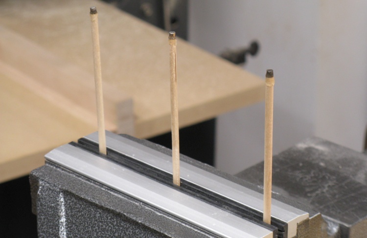
Magnet-tipped sticks for screw extraction
It's a bit difficult to extract screws from the rather narrow compartments with fingers alone so I made some magnet-tipped sticks to aid that process. After the epoxy has set on the three of them here, they will be stowed in the three drawers.
Complete
Installing the inserts, adding labels to the front panels and sticking rubber feet to the bottom completed the drawer set.
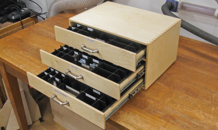
Drawers open and
almost tipping
The "open" view.
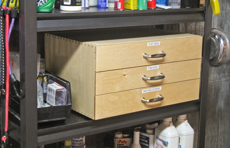
Installed in its permanent home
The drawers went into place back on the original screw shelf. There is still one (now somewhat emptier) bin beside it for larger bolts and screws.