
Warning! Stupidly long post. Do not attempt to read without strong coffee or amphetamines. Do not read while operating heavy equipment, surgical lasers or strategic bombers. In fact, probably best to just scan the pictures.
Details
I wanted a nice-looking shed for the yard, especially since it would be quite prominent for one of our neighbours. You can actually buy nice wood shed kits, but they are pretty costly and wouldn't be nearly as robust as a standard frame-constructed shed. With a bit of DIYing I figured I could build a nice one for maybe twice what a plastic shed costs. OK - maybe three times.
I looked into various shed designs and bought a plan (and downloaded some free plans too) but this was mostly to get me familiar with the methods and options for construction. For fun, I also downloaded a free 3D drawing program that let me sketch up some possibilities for the shed to see what looked good. After deciding on the specific dimensions, I drew up some 2D plans to generate a parts list and got going.
I looked into various shed designs and bought a plan (and downloaded some free plans too) but this was mostly to get me familiar with the methods and options for construction. For fun, I also downloaded a free 3D drawing program that let me sketch up some possibilities for the shed to see what looked good. After deciding on the specific dimensions, I drew up some 2D plans to generate a parts list and got going.
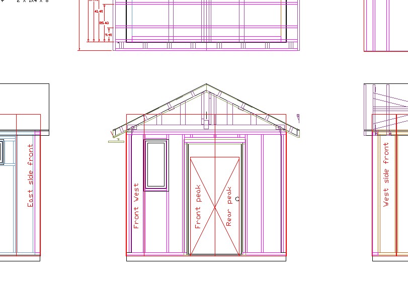
A small sampling of the plans
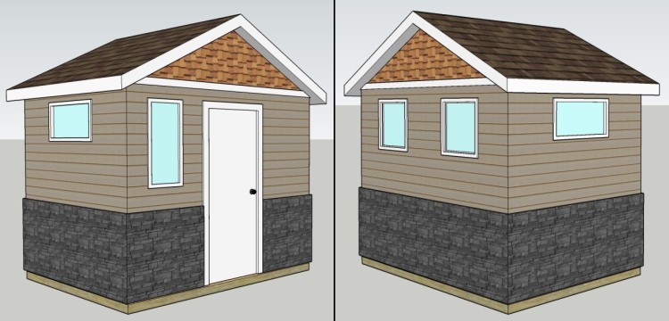
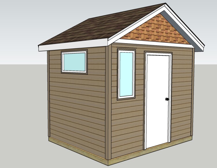
"Artist's conception" of the completed shed
Once we decided on a location for the shed and made sure it was OK with the near neighbours, the size was largely determined by what would fit; we settled on 7' x 9'. I also wanted a decent door - one which wouldn't make me duck to get in and out. That, along with what I thought was a nice slope for the roof largely determined the height.
I added a bunch of windows for light and played around with the finish and colours, and that initial concept is what you see here. The plans were drawn based on these dimensions.
I added a bunch of windows for light and played around with the finish and colours, and that initial concept is what you see here. The plans were drawn based on these dimensions.

Location marked out
There are a bunch of different ways to support a shed - concrete pad, pilings, timber base, etc. - and I settled on a bed of packed gravel.
For a gravel pad, a level area is going to be needed so the first step was to mark out the area and then see how much slope there was to the ground. Here string lines (barely visible in this picture) mark out an oversized area, with the strings all being level.
For a gravel pad, a level area is going to be needed so the first step was to mark out the area and then see how much slope there was to the ground. Here string lines (barely visible in this picture) mark out an oversized area, with the strings all being level.
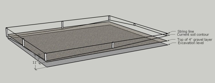
3D view of the required excavation
There was a fair amount of slope to the ground due to having the desired grade away from the garage for water drainage so there was about 7" difference between the highest and lowest corners.
I set the excavation depth to result in the shed floor being a couple inches higher than the ground level at its door.
I set the excavation depth to result in the shed floor being a couple inches higher than the ground level at its door.
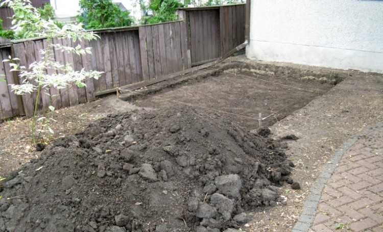
The area dug out and made roughly level
The area was excavated by shovel, with the dirt piled nearby until we could dispose of it. I estimated that about 1.3 yards of soil was removed.
The bottom needed to be about 11" below the string line, and I used the string you can see stretched between the sides as a reference. I moved the string so it was over the area of interest and checked depth with a tape measure. The 8' x 10' excavated area gave 6" space to the edge of the shed all around.
The bottom needed to be about 11" below the string line, and I used the string you can see stretched between the sides as a reference. I moved the string so it was over the area of interest and checked depth with a tape measure. The 8' x 10' excavated area gave 6" space to the edge of the shed all around.
The archaeology box
I threw any man-made objects I dug up into a cardboard box to see what had been in the soil.
It was about what you'd expect including various nails, screws, an electrical connector and one lonely tractor wheel. Not that I expected gold dubloons, but a couple of those certainly would have helped with the lumber bill...
It was about what you'd expect including various nails, screws, an electrical connector and one lonely tractor wheel. Not that I expected gold dubloons, but a couple of those certainly would have helped with the lumber bill...
Frame added for the gravel
The soil wasn't really deep enough in one corner to support my planned 4" of gravel, so I decided to make a frame to ensure the gravel wasn't washed away in a heavy rainstorm.
Ultimately I ended up building up the soil depth in the low corner, but the wood also provided a reference height that I thought could be used to help level the gravel. The frame was held in with stakes whose depth was adjusted so that the frame top was about 4" above the dirt level.
Ultimately I ended up building up the soil depth in the low corner, but the wood also provided a reference height that I thought could be used to help level the gravel. The frame was held in with stakes whose depth was adjusted so that the frame top was about 4" above the dirt level.
Sue dealing with the base gravel
We had a yard of base gravel delivered to the driveway, and wheel-barrowed it through the garage to the shed spot.
Starting to fill the area with a 2" layer
Recommendations are that gravel should be compacted no more than 3" at at time. Since we planned on a 4" thickness, we did it in a couple of 2-inch stages of which the first is started here.
We didn't bother renting a compactor and instead used a tamping bar, made from a 1" square steel rod with a 4"-square block of birch added to the end (seen standing up on the gravel). That was good for some sweaty work since it was a pretty warm day when we were doing the tamping.
You could tell when the gravel was adequately tamped because you could start to feel the vibrations from the tamper through your feet. It took only a few strikes with the tamper for full compaction since the gravel was nice and damp (which helps it compact), but of course it takes a while to do 80 square feet with a 1/10 square-foot tamper.
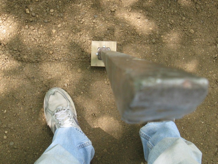
Tamper's-eye view of bar
When we bought the house there were a number of rusty metal things lying around, most of which have turned out to be useful over the years. One of them is the rod used as a tamping bar. It's a 1"-square steel rod with a bevel on one end and a cap welded to the other.
There was also a longer round steel rod with a cap (used for prying and tamping), several 18" long bolt-like things (used for temporary shelter anchoring) and an even larger and heavier steel rod as well as a large chain with hook (OK, haven't found a use for either of those yet).
There was also a longer round steel rod with a cap (used for prying and tamping), several 18" long bolt-like things (used for temporary shelter anchoring) and an even larger and heavier steel rod as well as a large chain with hook (OK, haven't found a use for either of those yet).
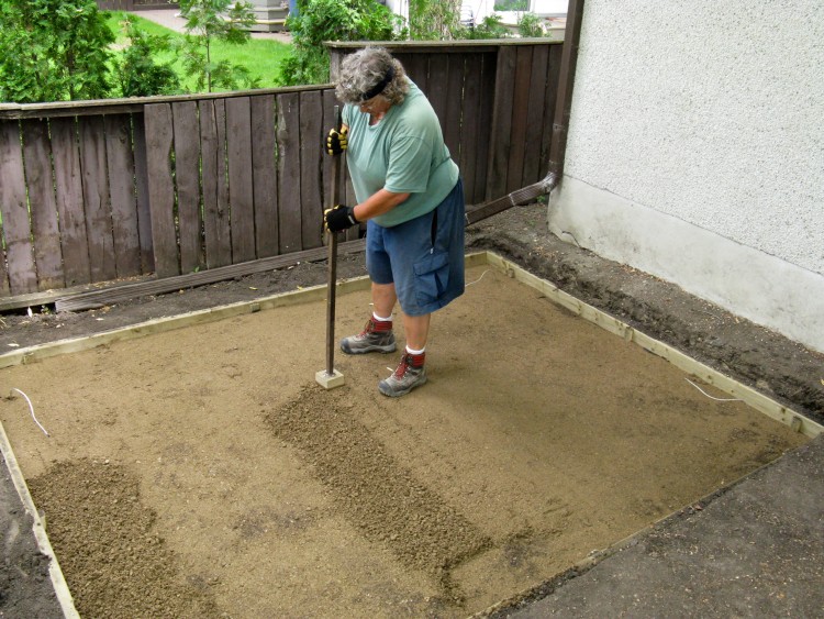
Tamping the first layer
Here Sue finishes up the tamping for the first layer before we put the rest of the gravel in.
In this picture can also be seen in each corner the cables for the "earth anchors". These are 4-inch long pointy metal bits with a cable attached that get pounded into the earth two or three feet deep, then get "set" by pulling on the cable. This causes the pointy ends to twist sideways to provide a high pull-out force. Given the hardness of the soil, there was zero chance of being able to actually pound the anchor points in as far as they needed to go. To get around this problem I made pilot holes by using a 5-pound sledge hammer to pound the iron bar used for the tamper in first, then pounded the anchor points down the resulting holes. Yes, building a shed is a good way to burn calories.
While there probably isn't much risk of the shed being upset by high winds, the anchors seemed like a fairly cheap bit of insurance against that.
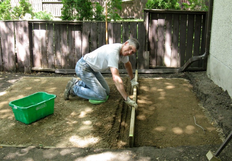
Screeding the gravel once it was all in place
You never know quite how much you are going to get when you order bulk material. In this case, I think we got a bit over a yard since it overfilled my 4" depth by about 1/2".
After tamping it all down roughly evenly, I made up a screeding board with extra 1/2-inch "lifts" on the ends so it could sit on the wood frame and be at the right height to shave off any extra gravel. Here I'm moving it back and forth to remove any high areas before re-tamping.
After tamping it all down roughly evenly, I made up a screeding board with extra 1/2-inch "lifts" on the ends so it could sit on the wood frame and be at the right height to shave off any extra gravel. Here I'm moving it back and forth to remove any high areas before re-tamping.
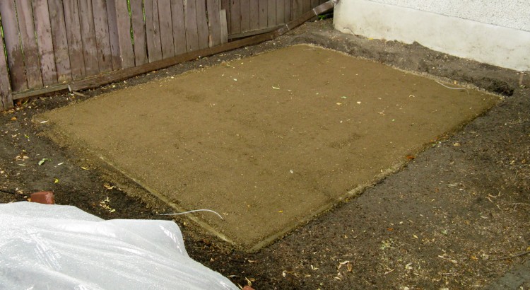
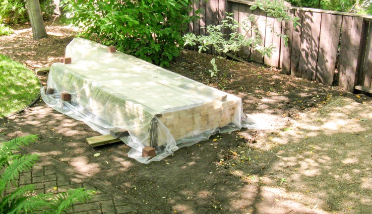
Gravel base levelled and tamped
This shows the area with the base completed. The nearby dirt pile is covered with plastic to avoid mud slides since it had been threatening to rain.
Big pile of 2x4s
And then one energetic morning, we shovelled all the dirt into a borrowed truck and took it to the compost depot. We made three trips to avoid overloading the truck, although we probably could have done it in two.
Then it was over to the Co-Op to pick up the lumber we needed including the 2x4s shown here as well as sheet goods stored elsewhere. For that task we took all the wood in one trip, although the truck would have been happier if we'd done it in two.
Then it was over to the Co-Op to pick up the lumber we needed including the 2x4s shown here as well as sheet goods stored elsewhere. For that task we took all the wood in one trip, although the truck would have been happier if we'd done it in two.
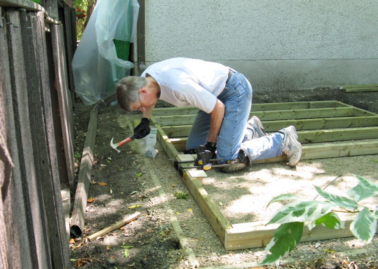
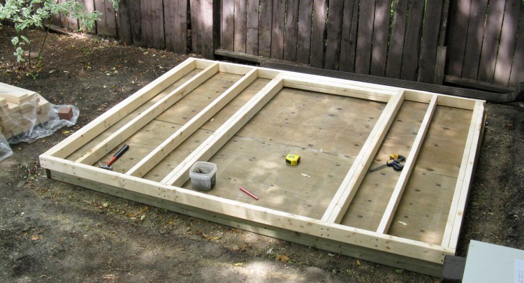
Starting on the floor frame
And then it was time to get the hammer out; I started on the floor, which was a standard frame with studs spaced at 16" and made from treated wood.
Visible in the background covered in plastic are the sheet goods; the OSB for sheeting and a couple treated plywood sheets for the floor.
Visible in the background covered in plastic are the sheet goods; the OSB for sheeting and a couple treated plywood sheets for the floor.
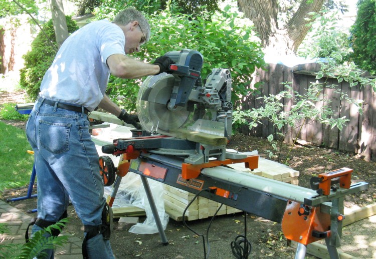
Deluxe chop saw lent by Gary (Thanks!)
For cutting the 2x4s, I used a nice Bosch Dual-Bevel Sliding Mitre saw lent to me by a buddy of mine who obviously has excellent taste in tools. He also provided the tool stand which was very handy for wood support.
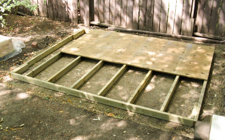
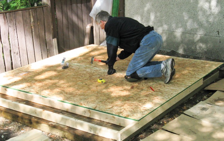
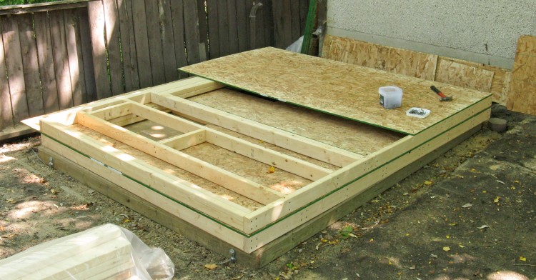
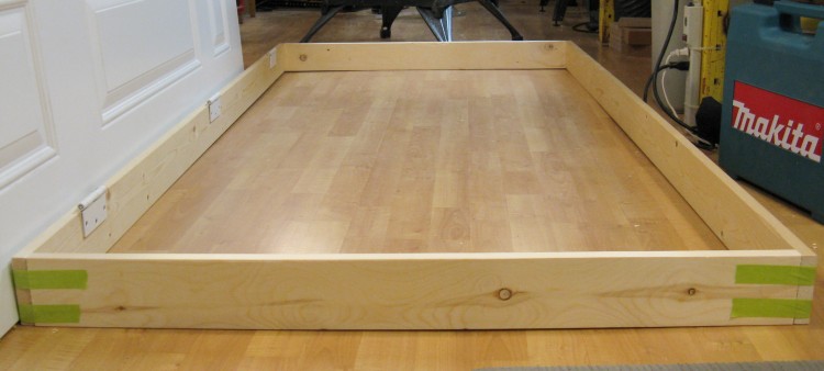
Starting to add the plywood floor
Once the frame was done, I started nailing on the 3/4" treated plywood for the floor.
In this shot you can also see the corner reinforcements on the frame, which were added for anchoring purposes.
In this shot you can also see the corner reinforcements on the frame, which were added for anchoring purposes.
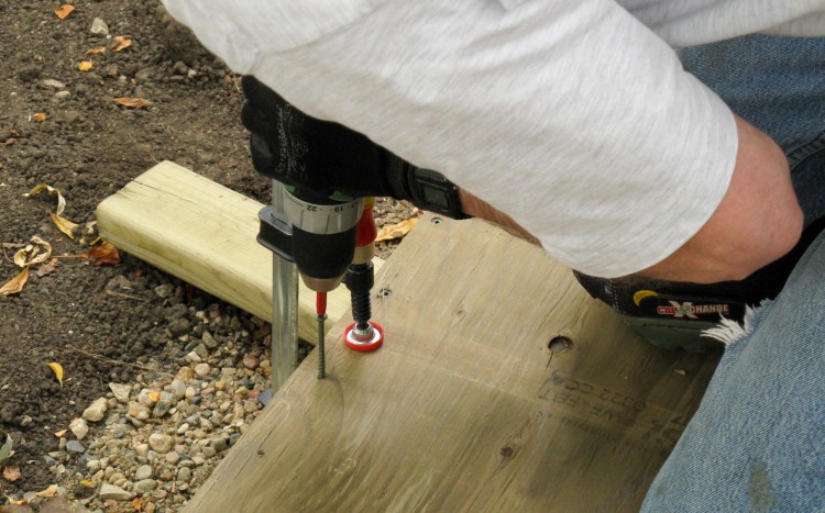
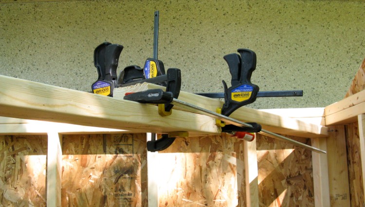
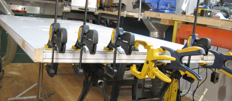
Some effort required to flatten warped plywood
Unfortunately, the whole pallet of 3/4" plywood at the Co-Op was rather imperfect with a warped edge. I had hoped screws or nails to the joists would flatten them, but that didn't work. I ended up having to use clamps to force the plywood flush with the frame while I drove in long screws.
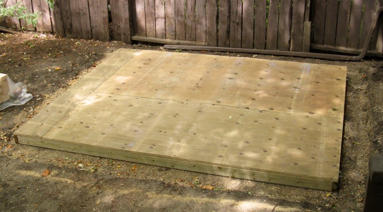
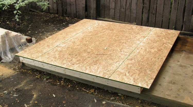
The completed floor
This shows the completed base. It took two sheets of plywood, with exactly one square foot left over.
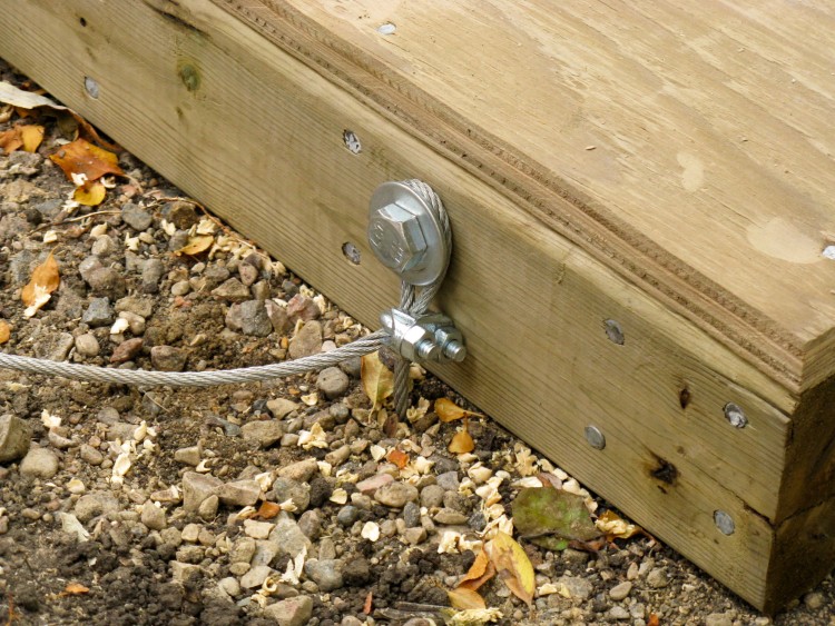
Anchor cable attached
I used a large lag bolt in each of the reinforced sections at the corners to connect the ground-anchor cables to the base.
This photo was taken on June 28, so the yellow leaves are not an indication of fall. Our ornamental crab tree has an issue where it starts to lose some fraction of its leaves in June and through August. Lack of Iron? Poor fertilization? Insufficient water? We've tried remedies for all these over the years and still we get Fall in June...
This photo was taken on June 28, so the yellow leaves are not an indication of fall. Our ornamental crab tree has an issue where it starts to lose some fraction of its leaves in June and through August. Lack of Iron? Poor fertilization? Insufficient water? We've tried remedies for all these over the years and still we get Fall in June...
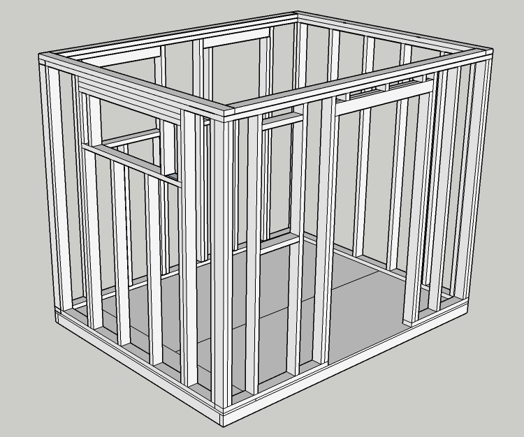
Gratuitous 3D framing model
With the floor done, it was time to start thinking about the framing. In addition to the 2D plans, I had also made a 3D model of the framing. Now this wasn't necessarily particularly helpful, but was kind of fun to do and gave a nice overall look at the shed "skeleton".
Starting on the front wall
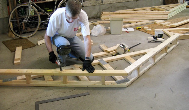
In accordance with what seems to be standard practise, I used the shed floor as a work surface and started by framing the front wall which includes the door opening.
The section of 2x4 at the bottom of the door will be cut out after the walls are raised.
The section of 2x4 at the bottom of the door will be cut out after the walls are raised.
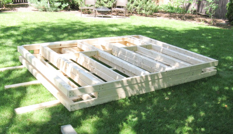
The mid-yard wall storage location
When a wall was done, I recruited Sue to help carry it onto the back yard lawn for storage. The framing was pretty quick, but I wasn't working particularly feverishly so typically just did one wall per day.
The first three walls are in this pile, with the short garage-side wall still being completed back on the shed floor.
The first three walls are in this pile, with the short garage-side wall still being completed back on the shed floor.
Adding sheeting to the garage-side wall
Sheeting the walls can be done either before or after they are raised. I thought I would do it before and so here I'm starting on the simplest one; the short 7' garage-side wall.
I hadn't done any calculations on how many nails I would need and just picked up an 0.881-pound box (damn you metric system!) of 2" nails for the sheeting when I was at one of my frequent visits to the Co-Op (no problem remembering my Co-Op number any more). I used up almost the whole box of nails on this first small wall and probably ended up using close to 5 pounds just for the sheeting by the time I was done.
I hadn't done any calculations on how many nails I would need and just picked up an 0.881-pound box (damn you metric system!) of 2" nails for the sheeting when I was at one of my frequent visits to the Co-Op (no problem remembering my Co-Op number any more). I used up almost the whole box of nails on this first small wall and probably ended up using close to 5 pounds just for the sheeting by the time I was done.
Garage-side wall done
Here the garage-side wall is done. The shed's front and back walls overlap the ends of the side walls, so the side wall sheeting needs to extend an extra 3-1/2" inches on the ends as can be seen here.
Now this brings up a logistical problem; Sue and I together can lift one of the side walls, even sheeted (barely) but only an unsheeted front or back wall. That means we couldn't move the larger walls after they were sheeted.
Now this brings up a logistical problem; Sue and I together can lift one of the side walls, even sheeted (barely) but only an unsheeted front or back wall. That means we couldn't move the larger walls after they were sheeted.
Sheeting the last wall (the front)
Our movement-mitigating plan was to sheet the two side walls and move them to the lawn, then sheet the back wall, leaving it on the shed floor and sheet the front wall on top of it.
This photo shows the last of the above-mentioned steps; sheeting the front wall on top of the back wall on top of the shed floor.
This photo shows the last of the above-mentioned steps; sheeting the front wall on top of the back wall on top of the shed floor.
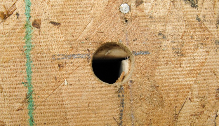
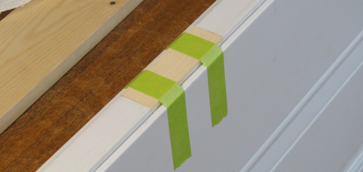
Locating the corner of the door cutout
Now normally when you add sheeting after the walls are up, you can mark the window and door openings to be cut out by driving a nail or drilling a hole in the corners of the opening from the inside. But with the walls lying down, these options weren't available to me.
Instead what I did was measure and mark where the corners should be, and then used a 1" drill bit in that area to remove the OSB and find out exactly where they were. I was pretty accurate on this one, but others were not quite as close.
Instead what I did was measure and mark where the corners should be, and then used a 1" drill bit in that area to remove the OSB and find out exactly where they were. I was pretty accurate on this one, but others were not quite as close.
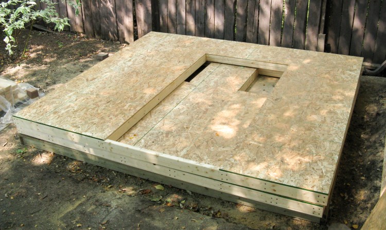
Sheeting cut out for door
After the corners were located, lines were drawn (with a pencil or chalk line) to outline the required opening which was then cut out with a circular saw. Here the door opening on the front wall (on top) is visible, as well as the edges of the window openings on the back wall underneath.
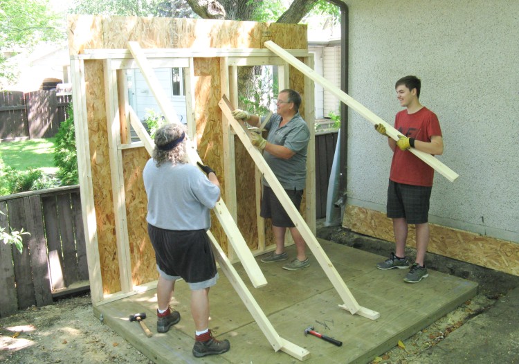
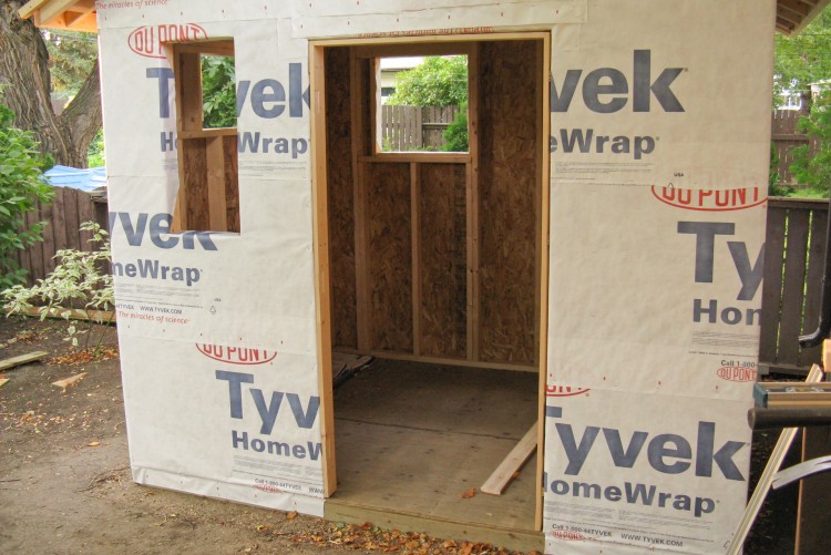
The wall-raising morning (well, 90 minutes)
We recruited my brother-in-law and nephew to help raise the walls of the shed one morning. After moving the sheeted walls on to the lawn and then marking the inside positions of the walls on the floor, we started with the back wall shown here (which everyone seems happy about) then did the side walls, and finally the front wall. I'm happy to report than no one was crushed.
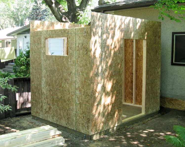
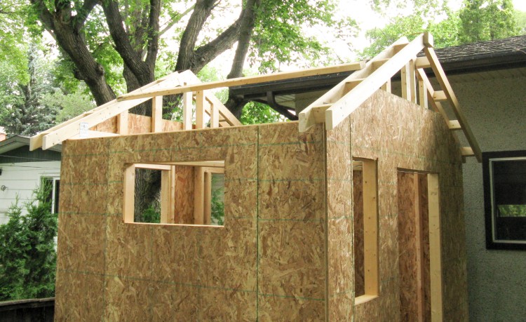
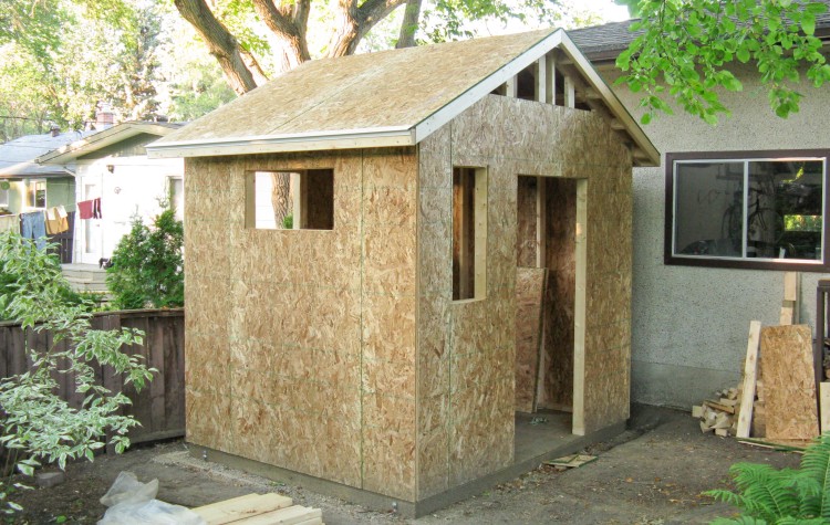
Starting to look a bit more sheddy
Here the four walls are up and attached. They weren't too far off vertical or square so they didn't need much adjustment. However, in the fine tradition of precision frame construction, things were tweaked to be a bit better by the judicious application of a sledge hammer in the appropriate corners.
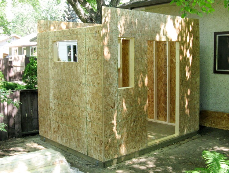
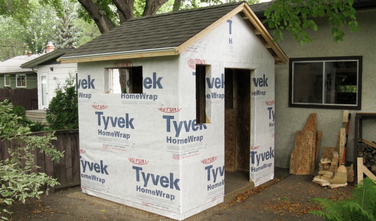
...and after cutting out the forgotten front-wall window
It was pointed out to me that there should have been a window beside the door, so a quick bit of work with the circular saw remedied that minor oversight.
The shed here looks a bit like it came out of a Western movie with the false front, but I just left the sheeting the full length since the gable was going to need to be covered anyway. I later trimmed the corners to match the roofline.
The shed here looks a bit like it came out of a Western movie with the false front, but I just left the sheeting the full length since the gable was going to need to be covered anyway. I later trimmed the corners to match the roofline.
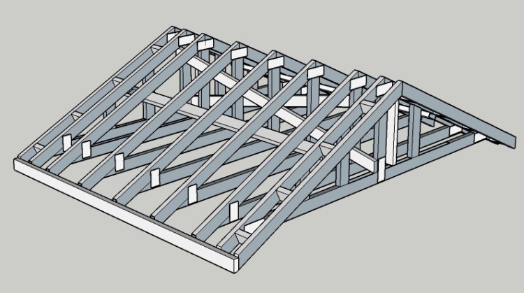
Truss arrangement with bracing & gable ends
The next stage was doing the roof. I decided to use trusses as opposed to building rafters directly on the shed. I used a simple style called a King truss and with my truss parameters of: "#1 or #2 spruce/pine/fir" wood, 9' span, 16" spacing and 2x4 truss construction, the strength came out to just about what you'd need based on snow load in my location.
I did up a 3D model of the roof mostly to be sure I understood where the truss bracing pieces would go (those are the 2x4s tying the trusses together). The braces distribute the forces between the trusses and the walls and prevent buckling to ensure you get the full strength from the structure. It may not be too critical for a shed, but a few extra 2x4s are not a big deal.
I did up a 3D model of the roof mostly to be sure I understood where the truss bracing pieces would go (those are the 2x4s tying the trusses together). The braces distribute the forces between the trusses and the walls and prevent buckling to ensure you get the full strength from the structure. It may not be too critical for a shed, but a few extra 2x4s are not a big deal.
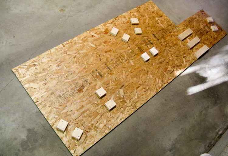
Truss construction jig
The trusses all need to be very similar to minimize roof dips and truss-end variation, so I made a jig to position the wood pieces accurately. It just consisted of an extended piece of OSB with 2x4 positioning guides nailed on.
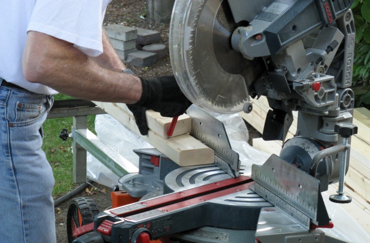
Marking a truss top piece
The mitre saw was set for a 26.5-degree angle to cut the top components of the trusses. Here I'm using a "pattern" piece to mark another 2x4 to prevent measurement errors.
After making sure my angles and lengths were accurate, I cut the top pieces for all the trusses so I woudn't need to change the saw settings.
After making sure my angles and lengths were accurate, I cut the top pieces for all the trusses so I woudn't need to change the saw settings.
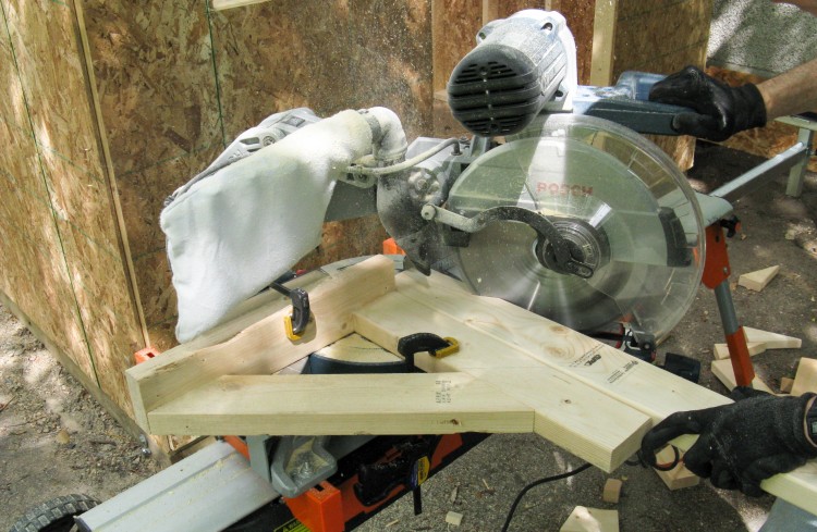
Right-angle jig added for cutting the small angle of the truss crosspieces
The cross pieces had a much "sharper" angle to cut. They needed to be 63.5 degrees from a 90 degree cut, but the saw doesn't move that far. So instead I made a right-angle jig and fed the wood straight in, which let me cut the crosspieces at the same saw setting as the top pieces.
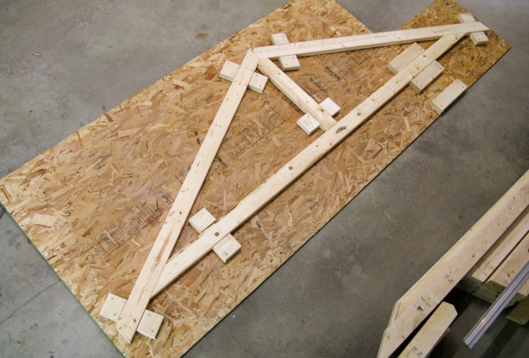
Jig loaded up
With all the truss components cut, I could then start to assemble them. Here is the first one with the wood positioned in the jig.

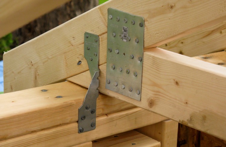
Assembling trusses with nailing plates
Shed trusses are often built using plywood to connect the pieces but I opted to use metal nailing plates. Many plates say specifically that they are not rated for structural work ("mending" plates), but I was able to find some that were properly rated, and used a couple different sizes.
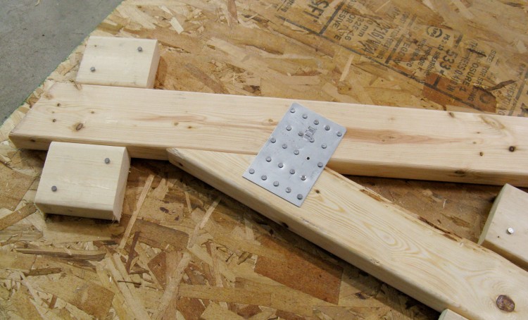
Alternate nailing plate that leaves room for hurricane ties
I used 3x7" nailing plates on most spots except for two corners where I used vertically-oriented 3x5" plates like the one shown here to provide room for brackets (called hurricane ties) securing the trusses to the shed structure.
I used plates on both sides of the truss with 1-1/2" nails in the plates and filled all the holes. Overkill again? Maybe, but it didn't take too long.
I used plates on both sides of the truss with 1-1/2" nails in the plates and filled all the holes. Overkill again? Maybe, but it didn't take too long.
Adding gable extensions to the end trusses
The two end trusses needed 6" extensions for the roof overhang and also extra studs to provide support for the gable materials. In this shot, the studs are mostly in place and I'm adding the extension.
I placed the studs flat rather than the traditional direction since that made them easier to install and it didn't make much strength difference for the short lengths involved.
I placed the studs flat rather than the traditional direction since that made them easier to install and it didn't make much strength difference for the short lengths involved.

Trusses ready to go
Here the full set of trusses is ready to go. I had to get them installed so I could park my pampered car in the garage again.
Clamp-powered stretcher to square up the shed frame before roof assembly
But before adding the trusses, I wanted to make sure the shed was square. While it was good at the bottom due to proper positioning of the walls, it wasn't great at the top. Using some 2x4s and clamps, I fashioned a stretcher to push apart the closest diagonal corners. This would stay on until the roof sheeting was installed, at which time the roof structure would hold things in place.
The end trusses in place
I once again recruited Sue, and we lifted the trusses into place starting with the two ends. Once these were properly positioned, a string was run between their centerlines as a guide for the other trusses.
You can also see a temporary outside brace between them that will be used to hold the rest of the trusses in place during assembly.
You can also see a temporary outside brace between them that will be used to hold the rest of the trusses in place during assembly.
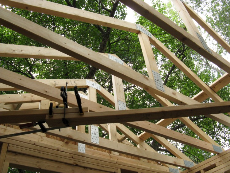
View from inside with trusses in place
This shot from the inside shows all the trusses in place. At this point they are just toe-nailed into the top plate and connected to the temporary brace.

Sue adding a hurricane tie
Hurricane ties were used to hold the trusses to the top plate. Here Sue is nailing in a tie above the side window. They were held with five nails per end.
Hurricane ties holding trusses to top plate
Here's a closer shot of a hurricane tie - there's one at each end of the truss. They are actually made to be mounted a bit differently, but the nailing plates limited the options and there's no reason to believe that this won't work just as well.
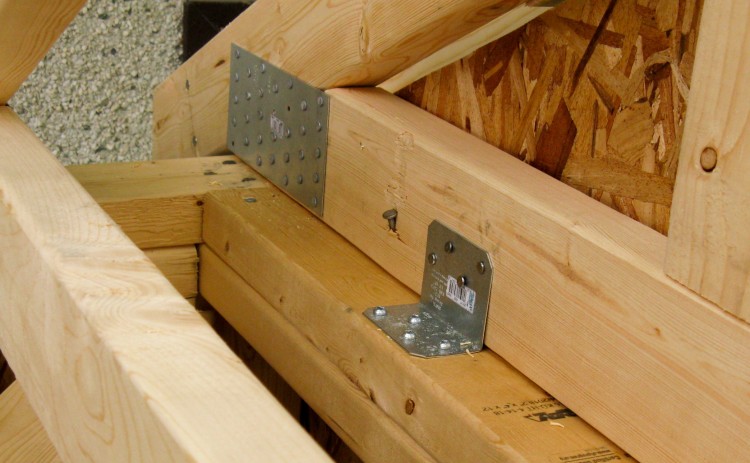
Brackets with nails & screws used for the end trusses
The end trusses needed something different for a hold-down technique so I used right-angle brackets nailed to the truss and screwed to the top plates.
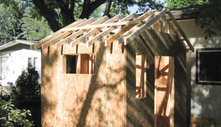
All trusses in place with temporary brace
This is the outside view with all the trusses in place.
Next up was to add four internal bracing 2x4s. That was pretty straightforward, except due to the odd nailing angles and limited hammer-swing space, it was some pretty slow work. It took the better part of an hour to do the seven nails on the first one, and I might have got that down to about 1/2 hour by the last one. The external 2x4 brace was removed when that was done.
And then I needed to add the fascia boards, which get nailed to the ends of the trusses on each side.

Some actual woodworking! (fascia board shaping)
The little insert diagram shows how I have it arranged in that the fascia board sits under the roof sheeting and needs the lower corner bevelled so the soffit could extend up at an angle along the trusses. Here I'm down in my shop shaving the corner off one of the boards.
When installing the fascia boards, I didn't want slight variations of truss end positions to cause the board to curve sideways in spots, so I used shims on the shorter truss ends to make sure it mounted straight. The thickest shim was only about 0.15" so there wasn't a lot of variation.
When installing the fascia boards, I didn't want slight variations of truss end positions to cause the board to curve sideways in spots, so I used shims on the shorter truss ends to make sure it mounted straight. The thickest shim was only about 0.15" so there wasn't a lot of variation.
Roof sheeting, fascia board and drip edge in place
Here the roof structure is complete with fascia boards, roof sheeting, internal braces and the white metal drip edge installed.
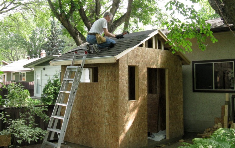
Starting to add the shingles
So then it's on to the shingling. I started on the easy side and first stapled on some #15 roofing felt (AKA tar paper) then followed with Iko Cambridge "Architectural" laminated shingles in Weatherwood colour.
Our house roof is a 4/12 slope (4 foot rise over a 12 foot distance) which is fine to be on. The shed however is 6/12, which gives me the feeling that I'm just about to lose grip and slide off.
Our house roof is a 4/12 slope (4 foot rise over a 12 foot distance) which is fine to be on. The shed however is 6/12, which gives me the feeling that I'm just about to lose grip and slide off.
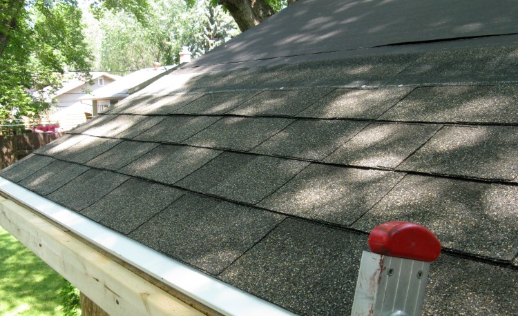
"Weatherwood" sorta neutrally-coloured shingles
Shingle close-up. I probably left too much of the white drip edge exposed - I'll just pretend it's a design statement.

Not a lot of room on the the garage side
I did the first few rows of the garage-side shingles from the ground on a short ladder, squeezing into the 12" or so between the shed eaves and the garage wall.
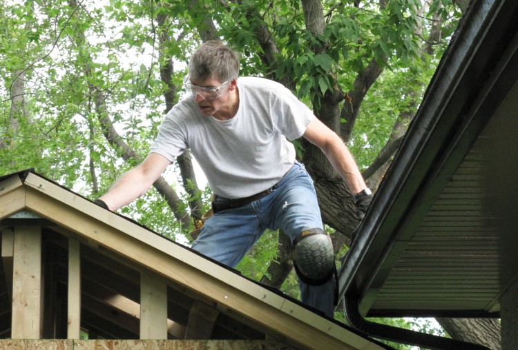
Moving to the top to finish the garage-side roofing
I then moved to the roof to do the rest of that side of shingles. In this shot you can see some narrow boards nailed on the ends of the eaves under the shingles. These were used as shingle cut-off guides and were later removed.
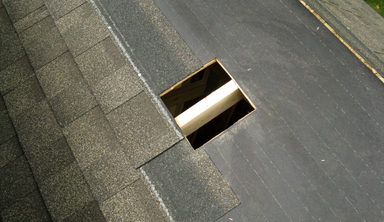
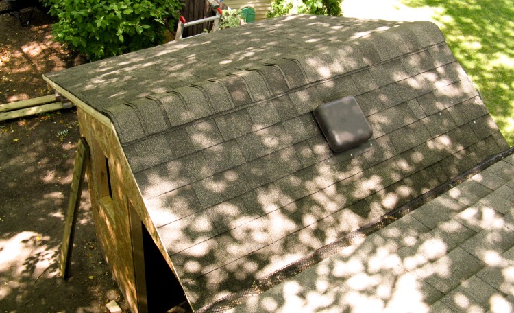
Hole ready for vent
I added a passive vent in the garage side, and this is the 8-1/2" hole cut in the roof sheeting for it.
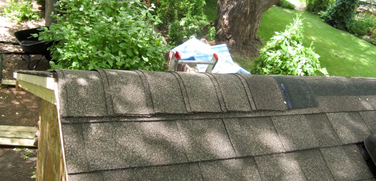
The ridge shingles partly done
Once the main shingling was done, I started adding a "ridge" version of the shingles to cover the peak. Here I'm about halfway done adding them. The one bundle I bought had more than I needed, so I went for the two-shingles-offset-by-3/4" approach for the "3D look".
Shingling on the roof is complete
Here is a shot of the completed shingling from the garage roof.
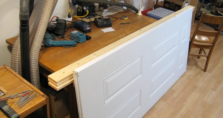
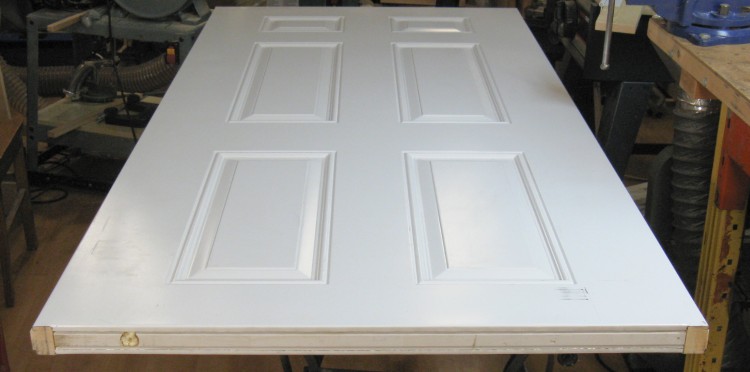
The door and wood for the frame
As I mentioned about 50 photos back, I wanted a decent door on the shed. My parent's shed had the sheet-metal-sliding-in-the-debris-filled-track doors that you needed to duck to get through and whose operation was anything but smooth. This one by contrast will have a metal-clad 36" external door on hinges with a locking handle. And there will be no ducking.
Since buying a pre-hung 36" external door is hard to justify for a shed ($300+), I instead checked out the Habitat for Humanity Re-Store and found this bare door at the cost of a nice meal for two. That meant that I would also need to build a frame for it, but those are theoretically pretty simple. The 1x4s on the table will be used for that.
Since buying a pre-hung 36" external door is hard to justify for a shed ($300+), I instead checked out the Habitat for Humanity Re-Store and found this bare door at the cost of a nice meal for two. That meant that I would also need to build a frame for it, but those are theoretically pretty simple. The 1x4s on the table will be used for that.
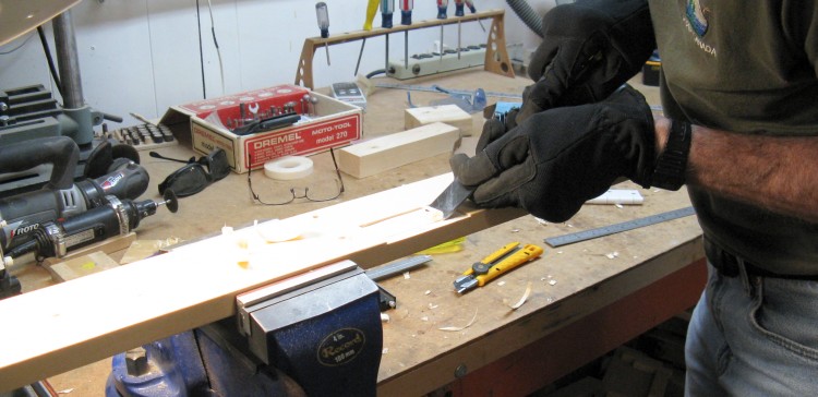
Cutting the hinge mortises in the door edge...
The door needed spots for the hinges, so I marked those and mortised them out using a chisel. This was easier than I had expected since I'm used to working with hardwoods, while wood on the door edge was a particularly soft softwood.
...and in the frame plank
The hinge mortises on the appropriate frame piece were done in a similar manner.
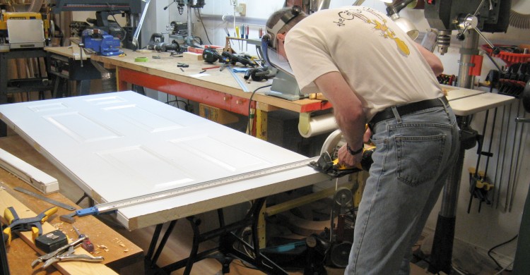
Shortening the door
A standard door is about 80" tall, but for the shed I wanted it to be only 75" so the door needed to be shortened. This is a bit involved with a metal-clad door, but armed with some YouTube-sourced knowledge I embarked on the shortening process.
In this shot, I had already cut off the bottom couple inches of the door as a test and am now starting the cut for the proper length just using a standard circular saw with a carbide blade.
In this shot, I had already cut off the bottom couple inches of the door as a test and am now starting the cut for the proper length just using a standard circular saw with a carbide blade.
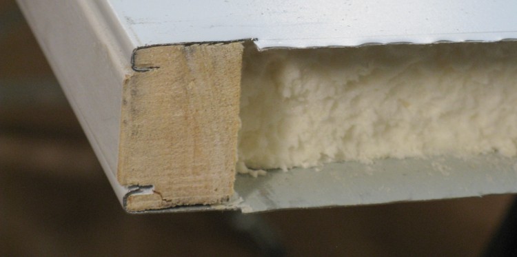
Recovering the wooden bottom piece of the door for reuse
The metal-clad door has metal faces, wood on the four edges, and the middle is foam-filled for insulation purposes. I needed to recover the bottom wood insert and here I'm stripping off the metal cladding from the short 2" piece I had cut off the bottom of the door.
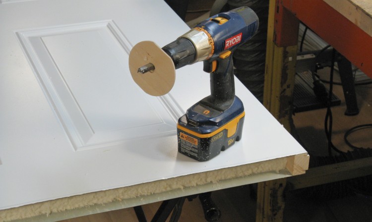
A makeshift router to cut out the foam to the proper depth
About one inch of the foam insulation needed to be removed to make room for the bottom wood piece. Here I made a makeshift router from a router bit and a drill with circular wood stop. Maybe I should get a router that isn't screwed to my router table...
Edge of the door shortened
The plan was to re-fold about 1/4" of the metal back over the bottom, so the door was cut 1/4" long. I needed to shorten the side wood inserts to be the finished length so here the extra 1/4" has been cut off using a jigsaw with a metal-cutting blade.
Bottom glued in place and clamped
In this photo, the recovered bottom wood piece has been re-inserted into the door and glued into place with PL adhesive. The clamps hold the metal cladding to the wood while the glue sets.

Bending the metal faces over the bottom piece
The last step of this rather involved door shortening is to bend the metal cladding back over the bottom wood insert. With a thick piece of oak clamped to the top to ensure the metal doesn't bow up, here I'm bending down the 1/4" flange in small steps using a brass-headed mallet and a piece of wood.
When this side was done, I flipped the door and did the same from the other side.
When this side was done, I flipped the door and did the same from the other side.
Completed door bottom
And voilà - a shortened door. All that remains to do is to paint the bottoms of the side pieces.
Some previously unnoticed hinge mortises - D'oh!
As I was flipping the door I noticed hinge mortises on the side opposite to where I had just cut them. In my defense they were painted white and difficult to see...
Filling in the extra mortises
Well, I didn't want mortises on the latch side of the door ("look how this doofus put me in") so I figured I'd better fill them in.
I cut some small wood slats which were then glued into place as shown here ("clamped" with masking tape).
I cut some small wood slats which were then glued into place as shown here ("clamped" with masking tape).

Embarrassment eliminated
A little sanding, a little exterior latex, and the whole extra mortise thing just goes away...
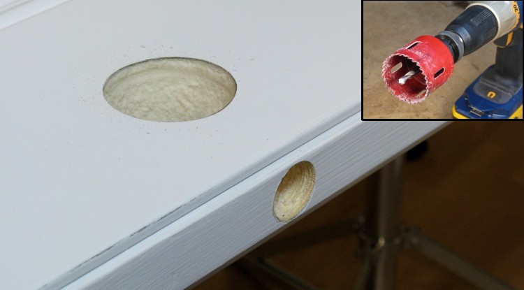
Lockset holes drilled
A hole saw was used to cut the knob opening. Despite being rated for metal, it wasn't too enthusiastic about going through the steel door, but persistence paid off. After drilling one side (and the guide hole through the other side), the door was flipped to be drilled from the second side.
A regular 1" Forstner bit was used for the latch passage hole.
A regular 1" Forstner bit was used for the latch passage hole.
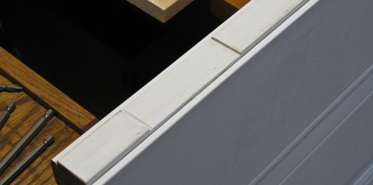
Frame assembled
OK, back on track here; I had already cut the wood for the frame to length, and those were put together with the top piece being screwed to the side pieces. In addition, there is a proper-length bottom piece that is just taped in to stabilize the whole thing while it gets moved and installed.
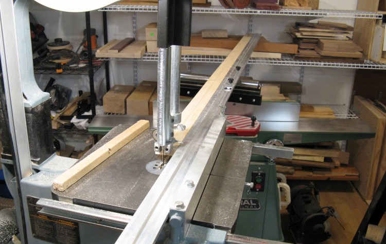
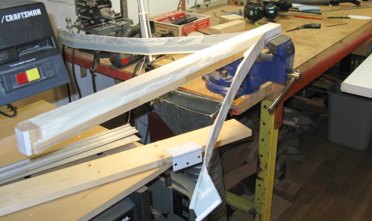
Cutting door stops
The frame needs some door stops in the center. I wanted those to be nice and straight to sit flush against the door, but the 1x4s I had were all warped a bit. Normally the jointer could be used to flatten an edge, but my shop isn't wide enough to joint a 6' piece of wood.
What I did instead was to tape a long aluminum straightedge to the wood and set that against the guide on the bandsaw. The cuts were therefore parallel to the straightedge making them nice and straight. After ripping to width and depth, one edge was rounded using the router, after which they were sanded and painted white.
What I did instead was to tape a long aluminum straightedge to the wood and set that against the guide on the bandsaw. The cuts were therefore parallel to the straightedge making them nice and straight. After ripping to width and depth, one edge was rounded using the router, after which they were sanded and painted white.
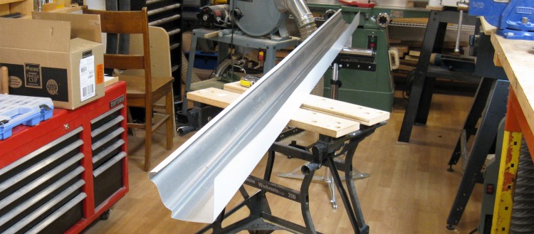
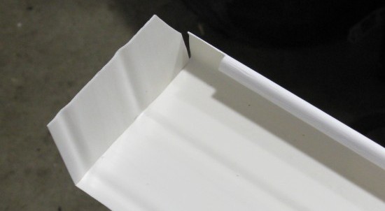
The aluminum eaves trough used as sheet metal source
For a maintenance-free exterior, a metal cladding is often used. Since I was building the frame from scratch, I got to make the cladding as well. You can buy rolls of metal to make cladding and flashing if you happen to have long metal-working tools like breaks and shearers, but I opted instead to start with a piece of aluminum eaves trough.
It was already painted and folded with a couple of 90-degree corners, so that eliminated a bunch of the effort that would otherwise be required.
It was already painted and folded with a couple of 90-degree corners, so that eliminated a bunch of the effort that would otherwise be required.
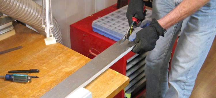
Angled pieces being cut to size
The edges of the metal would be covered so only the corner and faces needed to look presentable. Since the edges didn't need to be perfect, I could just use hand shears to cut out the proper width of metal as shown here.
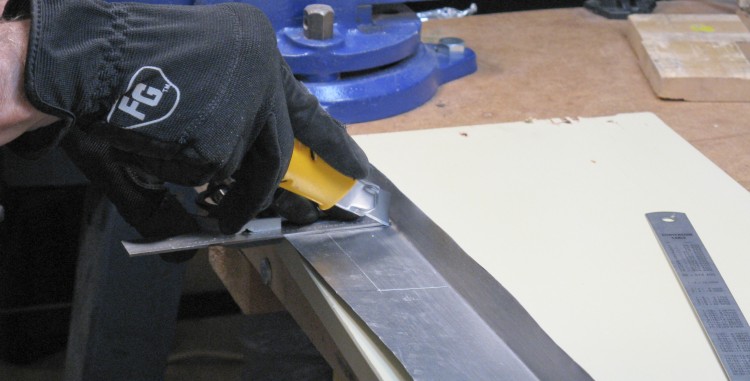
Cutting out openings for hinges
One side of the frame needed openings for the hinges and these were cut out using a sharp knife to cut most of the way through the aluminum. I then punched out the rectangular pieces, leaving a nice straight-edged opening.
There was also some bending and trimming to get the top and side pieces to overlap nicely, then these were set aside until the door frame was installed.
There was also some bending and trimming to get the top and side pieces to overlap nicely, then these were set aside until the door frame was installed.
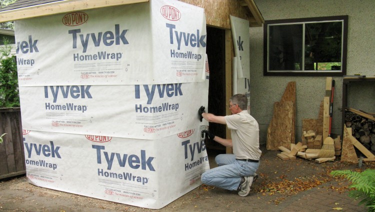
Starting on the house wrap
Before the door frame could go in, I needed to add the house wrap since it gets wrapped into window and door openings.
Here the three main courses have been attached just at their tops, and I'm starting to add the rest of the (stainless steel) staples. I'll finish up by doing the gables and cutting openings after that. The house wrap is another case of "is it really needed?", but again I erred on the side of caution.
Here the three main courses have been attached just at their tops, and I'm starting to add the rest of the (stainless steel) staples. I'll finish up by doing the gables and cutting openings after that. The house wrap is another case of "is it really needed?", but again I erred on the side of caution.
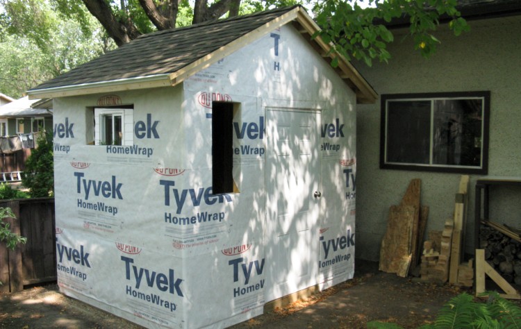
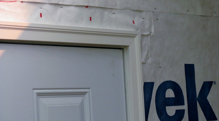
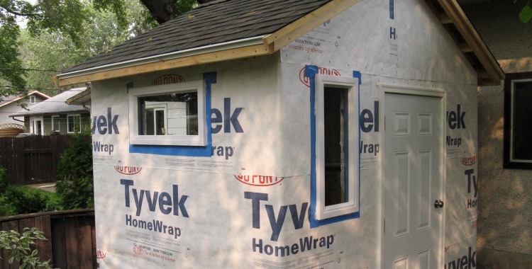
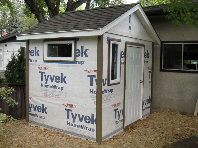
Shed wrapped
House wrap is complete in this picture.
Y'know, if they just printed something like a brick pattern on the wrap, the shed would be almost done now...
Y'know, if they just printed something like a brick pattern on the wrap, the shed would be almost done now...
Door frame in place
The door frame went in next. It was adjusted with shims to get it vertical and consistently spaced along the length.
After that was done, the door was mounted and mortises for the door latch and the jamb strike plate were carved out.
After that was done, the door was mounted and mortises for the door latch and the jamb strike plate were carved out.
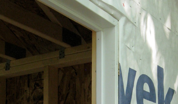
Door frame detail
Once the door and latch were working, the metal trim and door stops were added. The trim ends under the stops, and nails through the stops also hold the metal trim in place.
An actual working door
Shed with door installed.
"Artist", now older and wiser, revises his conception
I had been thinking about the outside treatment of the walls, starting with the faux rock portion on the bottom. I had my eye on a product sold by the Co-Op but they had no prices for what they had on display, so I came up with a detailed list of what would be required to get a quote. I was gaberflasted to find that the plastic panels worked out to over $20 per square foot and it would have been over $2000 for the shed. There were other brands of faux rock that were presumably less expensive but they also looked extra-cheesy so they didn't seem worth the trouble.
Ah well, on to Plan B, which which was to use full vinyl siding. The revised concept in the approximate color, and with the various vinyl siding trim pieces is shown here.
Ah well, on to Plan B, which which was to use full vinyl siding. The revised concept in the approximate color, and with the various vinyl siding trim pieces is shown here.
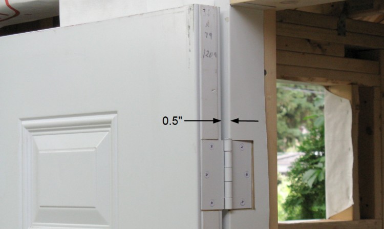
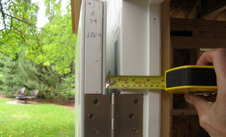
Siding 0.9" thick. Uh-oh.
After the door was installed I started looking at the frame around it. I had bought some PVC brickmould which was a bit over an inch thick and found when I was fitting it that the door wasn't going to be able to open fully. The door would hit the moulding since the space between the wall and the door was only 0.5". Even the vinyl siding was going to be around 0.9" thick. Oops - that was a dimension I forgot to think about.
I definitely wanted the door to open 180 degrees, so something needed to be fixed. After some thought, it looked like the hinges could just be changed from the 3-1/2" models I used to 4" models. This would move the door out another 1/2" to give about 1" of clearance which should be enough.
I definitely wanted the door to open 180 degrees, so something needed to be fixed. After some thought, it looked like the hinges could just be changed from the 3-1/2" models I used to 4" models. This would move the door out another 1/2" to give about 1" of clearance which should be enough.
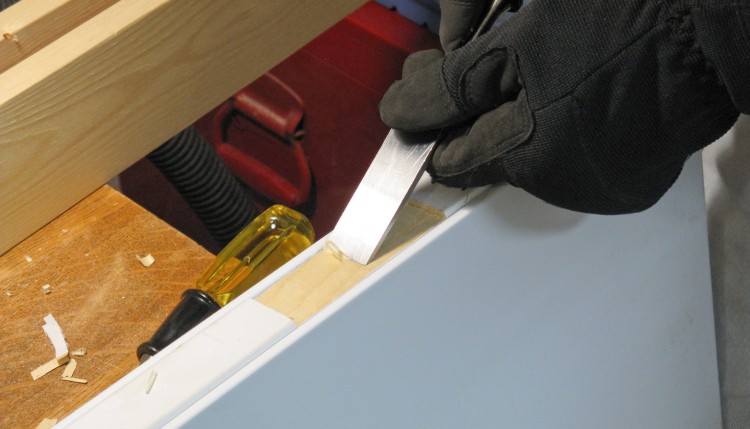
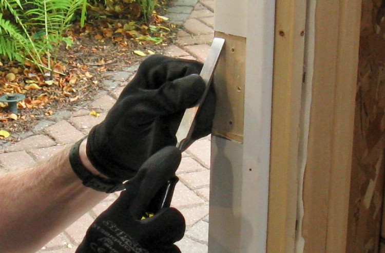
Metal opening expanded for new hinges
The new hinges would be 4 x 4" so I needed to expand my 3-1/2" openings. After removing the door and hinges I trimmed the metal cladding about 1/4" on both top and bottom. I used a sharp knife with a ruler to score the aluminum and then used pliers to "rip" along the lines.
Hinge mortise height being increased
Then using a chisel, the mortises were expanded to accommodate the new hinges. The same was done on the edge of the door.
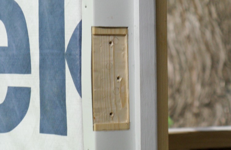
The new hinges had four holes, two of which came close to existing holes, so I fashioned some plugs from 2x4 material and glued them into the existing holes (on both the frame and the door) to make sure the new screws held well.
The new hinges had four holes, two of which came close to existing holes, so I fashioned some plugs from 2x4 material and glued them into the existing holes (on both the frame and the door) to make sure the new screws held well.
Increased clearance
Then with everything back together and the new hinges in place, I was happy to find that the door still closed correctly. And the clearance to the wall is the one inch that I needed.
Brickmould added around door
So then back to what I was doing before the door clearance fix; the door frame trim (brickmould) was added after thinning it on the bandsaw from 1.25" to just under 1".
This is a solid PVC product and won't need to be painted. It gets installed using longish expensive-ish specialized screws. The screw heads embed about 3/8" into the plastic, and then the holes are filled with little white plugs to make them invisible (at least in a low-resolution photo like this one).
This is a solid PVC product and won't need to be painted. It gets installed using longish expensive-ish specialized screws. The screw heads embed about 3/8" into the plastic, and then the holes are filled with little white plugs to make them invisible (at least in a low-resolution photo like this one).
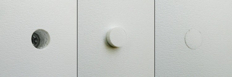
Trim plugs
Sort of like that.
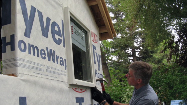
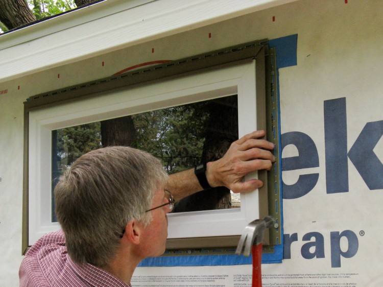
Installing one of the rear windows
I figured that it was time to install the windows and keep debris out of the shed. After levelling this rear window from the inside, here I'm back outside nailing through its nailing flange.
Afterwards, the flanges will be covered with a self-adhesive flashing to prevent water leakage - probably another "overkill" step.
Afterwards, the flanges will be covered with a self-adhesive flashing to prevent water leakage - probably another "overkill" step.
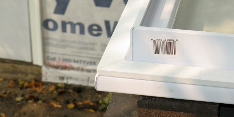
Thickened window frame
The rear windows are "real" windows, while the other two are "shed" windows and are a different design. The flange on the shed windows will sit right against the wall and since the flange is only 3/4" thick as compared to 0.9" for the siding, they would be recessed which I thought might look odd.
To bring them out a bit, I added an 0.3" frame made from the cutoffs of the door brickmould. These were glued on with a bead of sealant so that the joint would be waterproof.
To bring them out a bit, I added an 0.3" frame made from the cutoffs of the door brickmould. These were glued on with a bead of sealant so that the joint would be waterproof.
Front and side windows in too
After adding the blue flashing, the windows were installed with a bead of sealant to seal to the flashing, and then they were nailed from the inside to hold them in place.
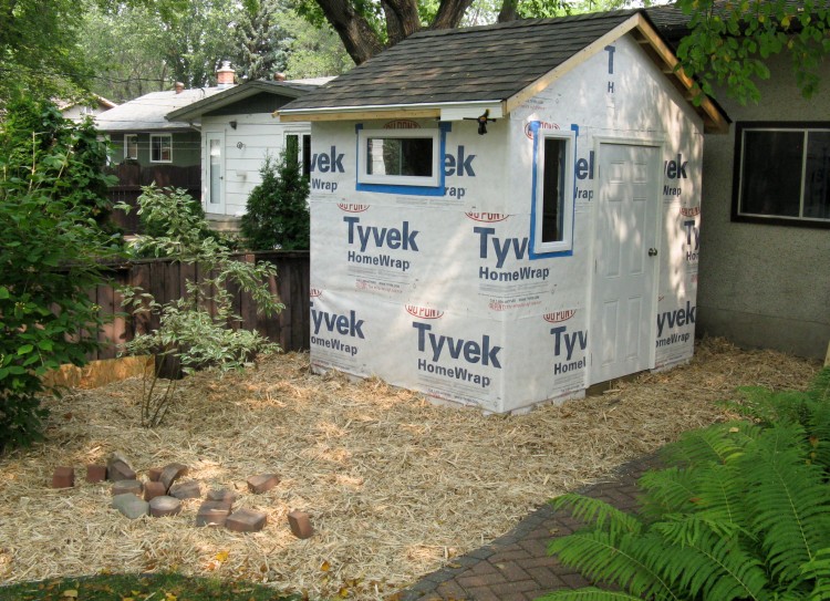
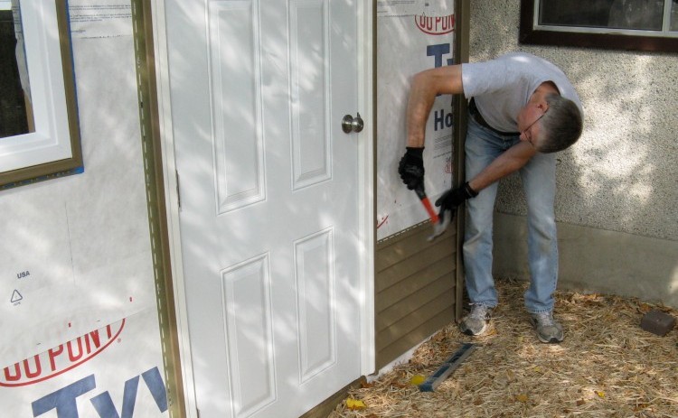
Some mulch added to cover the dirt
The dirt needed some cover so that things didn't get muddy when it rained, so we spread some "post peelings" pine mulch around the shed.
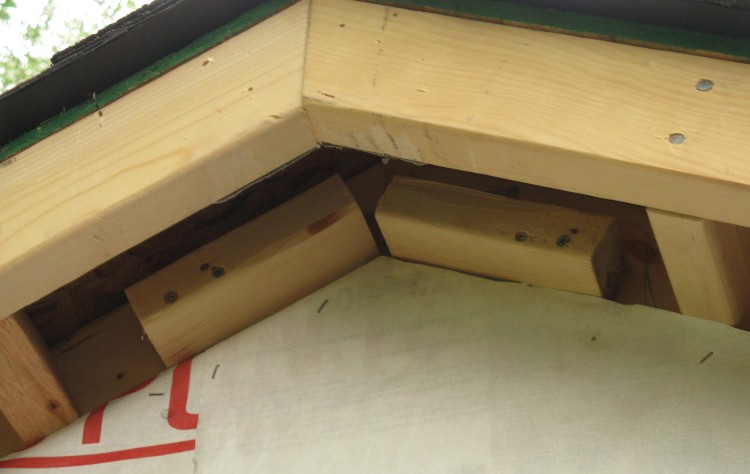
Added supports for soffit channel
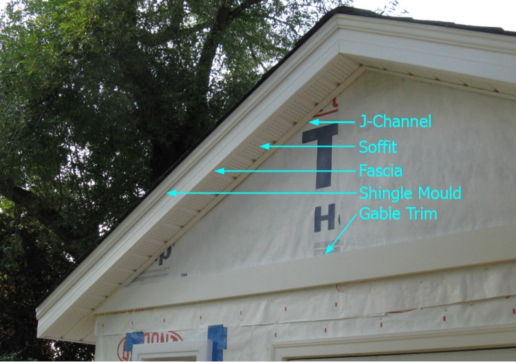
So then it was time to start on the soffit and fascia, which turned out to be a huge pain in the ass very involved detail-oriented challenge!
It started with adding some additional support for the soffit as shown here, and then trimming and cutting and bevelling the PVC J-channel, soffit, fascia and trim pieces.
It started with adding some additional support for the soffit as shown here, and then trimming and cutting and bevelling the PVC J-channel, soffit, fascia and trim pieces.
Trimming, cutting, fitting, etc. etc.
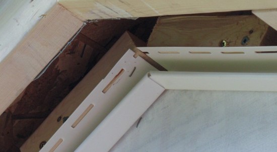
Trim finally done
The soffit J-channel went up first just under the eaves, with the ends trimmed as necessary to mate at the side and top corners.
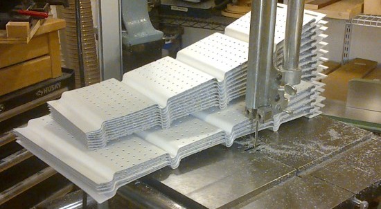
Once that was up I figured out how best to trim the fascia for unobtrusive joints, but before that could go up the 12' pieces of soffit needed to be cut up into little short sections, which was done mostly with the bandsaw.
Then I could insert the soffit pieces into the J-channel attached to the shed and add the fascia cover. These were held on with nails, which were then covered up on the gables with some decorative "shingle mould", screwed in place.
Finally strips of horizontal gable trim were added to separate the walls from the gables. Whew.
Then it was finally time to move on the siding. Of course, the first step of doing siding is to install all the trim around the windows, doors and edges. Fortunately, I just had lots of practise;
And then the siding trim...
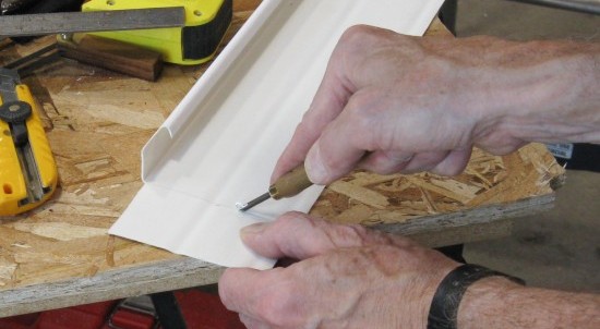
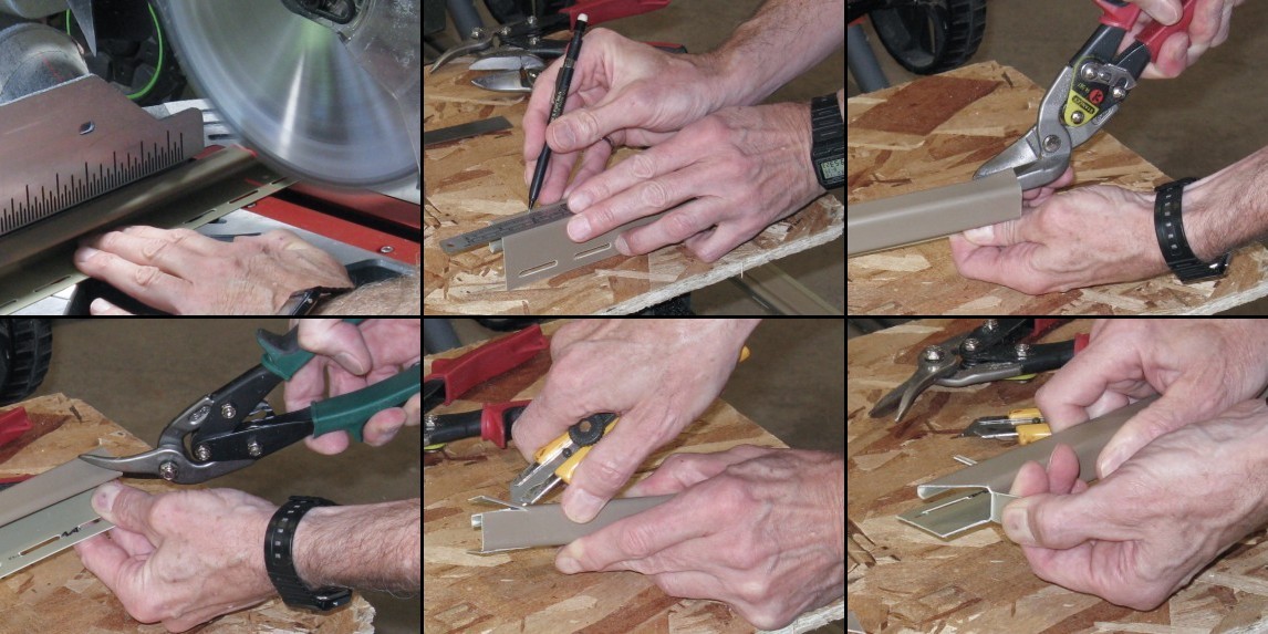
Assembling window trim
The above montage shows one of the J-channel trim pieces being cut to shape. This one will go along the top of a window with the bent-over tab inserting into a slot in the vertical side piece. There were about 24 pieces in all that needed to be cut to length and trimmed appropriately at each end.
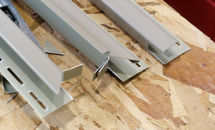
The image to the right shows some of the trimmed ends.
The image to the right shows some of the trimmed ends.
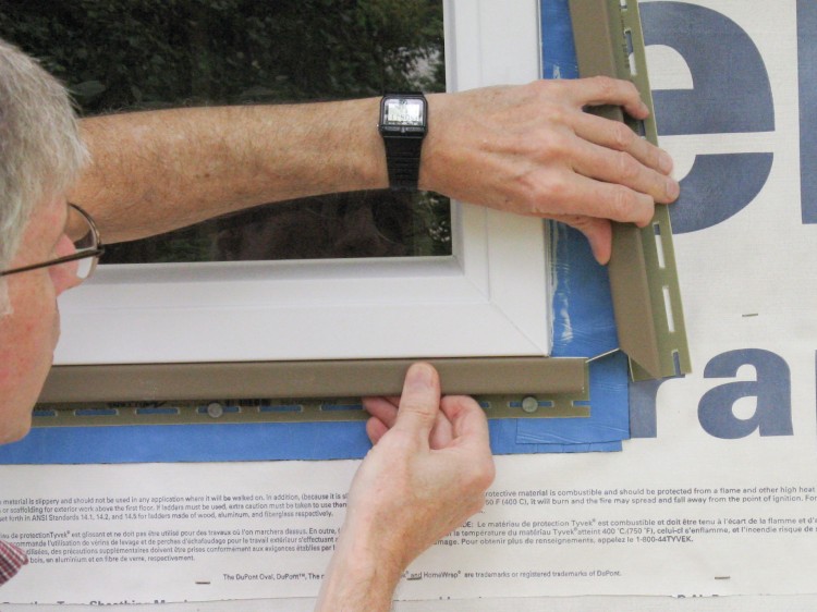
Assembling window trim
Here the trim is being assembled around one of the back-side windows.
The vinyl siding installation instructions (from a couple manufacturers and the Vinyl Siding Institute) are all pretty horrible. For one example, they describe the nails that should be used including shaft and head diameter. It turns out the only type of nail that fits the requirements is a roofing nail. You'd think they might just say "use a roofing nail", but no. Inconsistencies and omissions abound.
The vinyl siding installation instructions (from a couple manufacturers and the Vinyl Siding Institute) are all pretty horrible. For one example, they describe the nails that should be used including shaft and head diameter. It turns out the only type of nail that fits the requirements is a roofing nail. You'd think they might just say "use a roofing nail", but no. Inconsistencies and omissions abound.
Attaching trim
For those with as much vinyl-siding installation experience as myself (none), I'll mention that due to expansion with temperature the trim and siding has slots for the nails and is not nailed tightly, this to allow the vinyl to expand and contract without buckling.
All building edges (of walls, roof, doors and windows) need a trim piece of an appropriate type added to accept the edges and ends of the siding. Here a J-channel is being nailed around one of the windows.
All building edges (of walls, roof, doors and windows) need a trim piece of an appropriate type added to accept the edges and ends of the siding. Here a J-channel is being nailed around one of the windows.
Siding trim mostly done
In this shot, most of the trim is in place including the J-channel around the door and windows, the outside corner pieces and the starter strip at the bottom. Only the J-channel at the top of the walls is missing.
Starting on the first little section of vinyl siding
With the trim up, I could start installing siding. I used a Triple 3 inch type which has three "siding" rows each about 3" high in an overall 10" height. In this shot I'm nailing on the second piece of siding.
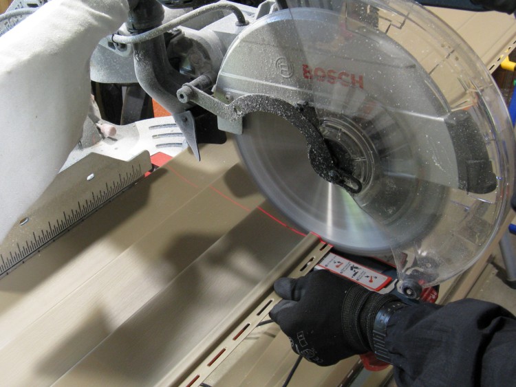
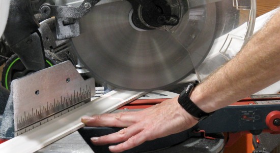
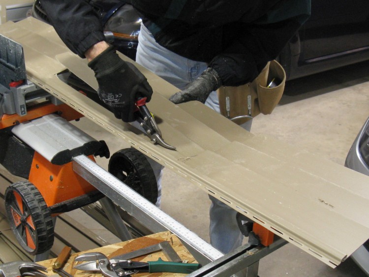
Cutting the siding
I was able to cut the siding using the mitre saw. As per recommendations, the blade was installed in reverse so the saw kind of wore its way through rather than actually cutting, but it still made a nice smooth edge. This saw has a laser indicating the location of the cut, which was very handy.
I found with my one try at cutting the vinyl with the blade in the normal way that it tends to shatter the vinyl.
I found with my one try at cutting the vinyl with the blade in the normal way that it tends to shatter the vinyl.
Cutting out a window opening
The vinyl siding needed to be cut out to fit around the windows and door. To do that it was marked, the edges cut part way through with the mitre saw, and then the piece cut off with tin snips.
This particular piece will be mounted over the top of the side window.
This particular piece will be mounted over the top of the side window.
Siding making its way up the shed
The siding went on with 1-1/2" galvanized roofing nails. I had kept track of what was spent on the shed so I was able to do a bit of nail-based data analysis. The stats showed that I purchased various types of nails on no less than 11 separate occassions, for a total of $159. Just for nails.
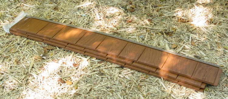
Some vinyl shakes for the gables
The siding covered only the lower walls, with the gables left to be covered by a different material. I had chosen a vinyl "cedar shake" which came in panels as shown here.
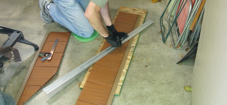
Trimming the shakes with a utility knife
The shakes were trimmed to the roof angle using a knife and straightedge so they fit closely under the soffit. To cover the edges, I also modified some white J-channel (so it was narrower) which was then mounted to the eaves.
Siding complete!
And in this photo the siding and shakes are complete.
The only remaining outside bits are the eaves troughs.
The only remaining outside bits are the eaves troughs.
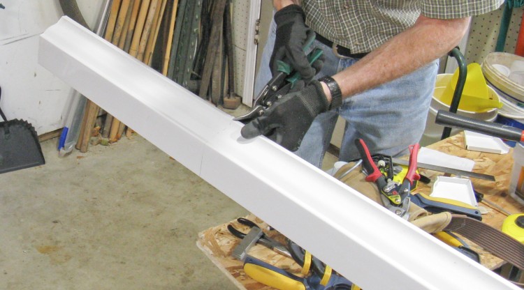
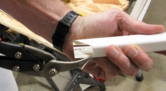
Cutting eaves trough to length
I selected aluminum eaves trough for the shed, and here I'm using "aviation snips" (AKA tin snips) to trim the length to match the eaves.
After trimming, they will have a downspout hole cut out, a plastic spout glued in and end caps will also be glued on.
After trimming, they will have a downspout hole cut out, a plastic spout glued in and end caps will also be glued on.
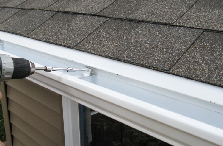
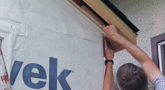
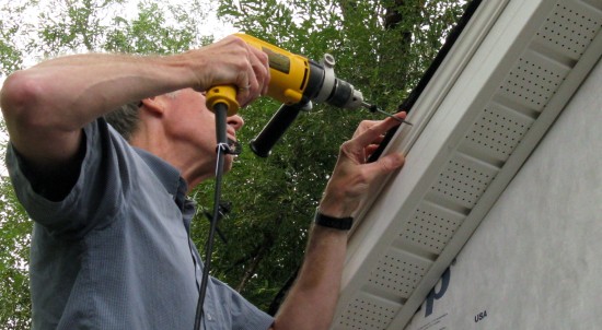
Mounting the eaves trough
The first of the eaves troughs is being mounted here with a slight slope (1/4" over the 8 feet) toward the downspout for drainage. The drip edge has had slots cut in it, which were then bent up to provide clearance for the mounting brackets. The back of the trough is mounted under the drip edge, and screws through the aluminum brackets hold the trough to the fascia board.
The eaves trough on other side wasn't quite as easy since there wasn't room for the drill between the shed and the garage wall, so the screws went in manually with a nut driver and a ratchet.
The eaves trough on other side wasn't quite as easy since there wasn't room for the drill between the shed and the garage wall, so the screws went in manually with a nut driver and a ratchet.
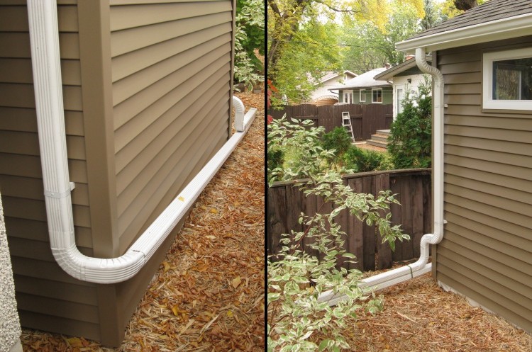
Eaves trough done
Downspouts were run from each side of the shed to empty out a bit further back in the yard. The garage roof eaves trough was also modified to dump into the near-side trough of the shed to reduce the number of drainpipes needed.
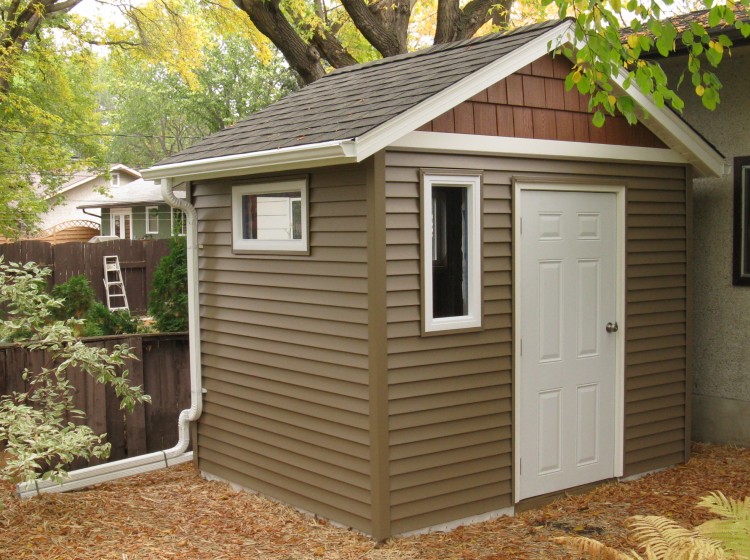
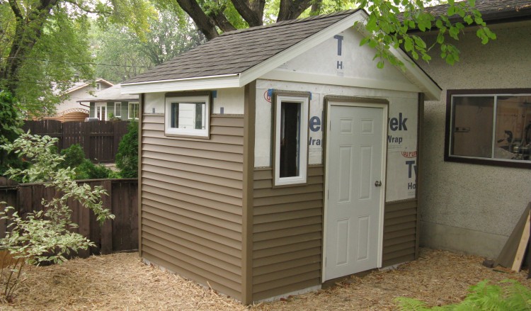
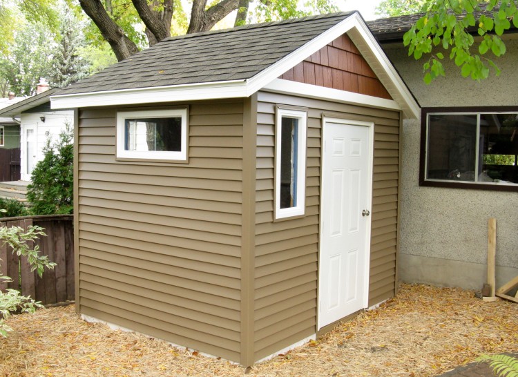
Completed shed
Here is a shot of the completed shed.
It was started mid-June and completed almost exactly 3 months later. I'd guess that I might have averaged a couple hours a day on it, so it probably took in the ballpark of 180 hours - equivalent to 4 or 5 weeks worth of full-time work.
It was started mid-June and completed almost exactly 3 months later. I'd guess that I might have averaged a couple hours a day on it, so it probably took in the ballpark of 180 hours - equivalent to 4 or 5 weeks worth of full-time work.
Post-game analysis:
The head statistician reveals that I made 31 purchasing trips to (in alphabetical order) Burron Lumber, Canadian Tire, Co-Op Home Center, Habitat For Humanity Re-Store, Home Depot, Home Hardware and Rona. That's only to make actual purchases, so pre-purchase scouting expeditions were in addition to those.
As for my original cost guesstimate of two or three times the cost of a plastic shed, well at $3263 it is definitely at least three times.
The Breakdown:
| Wood | $1030 |
| Siding/shakes | $594 |
| Trim (facia, soffit, etc.) | $335 |
| Windows | $225 |
| Hardware (anchors, etc.) | $222 |
| Eaves Trough | $210 |
| Roofing | $175 |
| Door & hardware | $169 |
| Nails | $159 |
| Sealing (housewrap, etc.) | $96 |
| Paint (for floor) | $48 |

Interior shot
And the inside? Well, it's mostly "unimproved" except for the addition of a couple of 18"-deep wire shelving units.
The plan is to paint the floor white to brighten it up a bit more and make it easier to sweep out, but since the weather has been sub-10 Degrees, that may need to wait until next year.
The plan is to paint the floor white to brighten it up a bit more and make it easier to sweep out, but since the weather has been sub-10 Degrees, that may need to wait until next year.


