I thought I'd make the new tables pretty much identical to the original aluminum version so I started by measuring that one up and based the plans on those numbers. The new table dimensions ended up almost the same except for some liberties taken in shape of the top planks and leg straps. The original has a square-edged grey industrial feel going but I like to think that the new ones are a shade more relaxed-looking.
It was a bit more convenient to measure the table in metric as opposed to imperial (for example the legs were 20 mm wide rather than 25/32") so I ended up doing the drawings in metric as well. That worked fine although I confess I'm still more comfortable with my old friend the inch. However when you find mentions of dimensions below in millimeters, this is why.
The purpleheart is a pretty good fit to this type of table; the wood is strong and straight-grained which works well with the linear shape of most of the pieces. The original mostly used rivets for the hinged joints while the wood version uses stainless steel bolts.
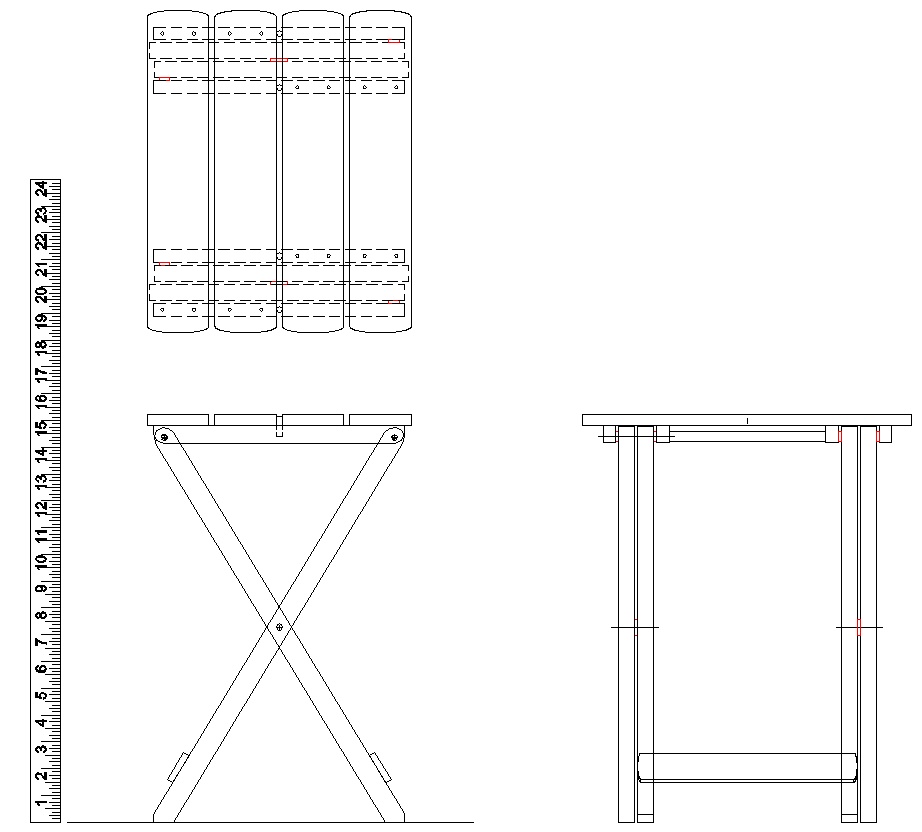
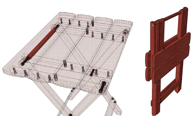
The table, drafted in millimeters (but with an imperial ruler for old fogies)
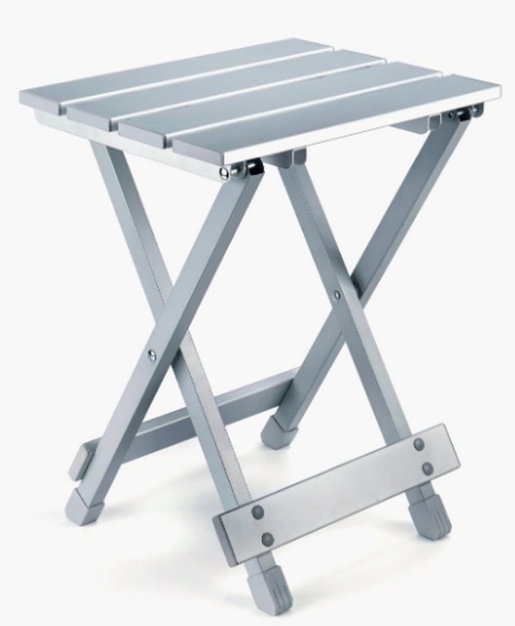
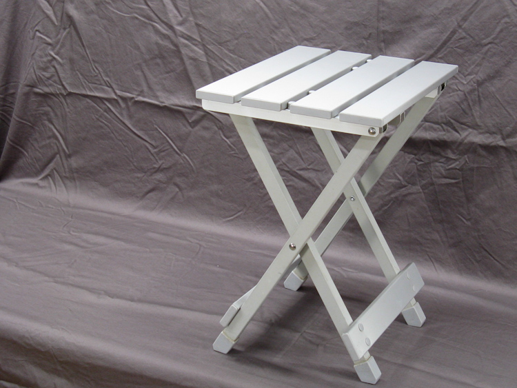
The original aluminum specimen
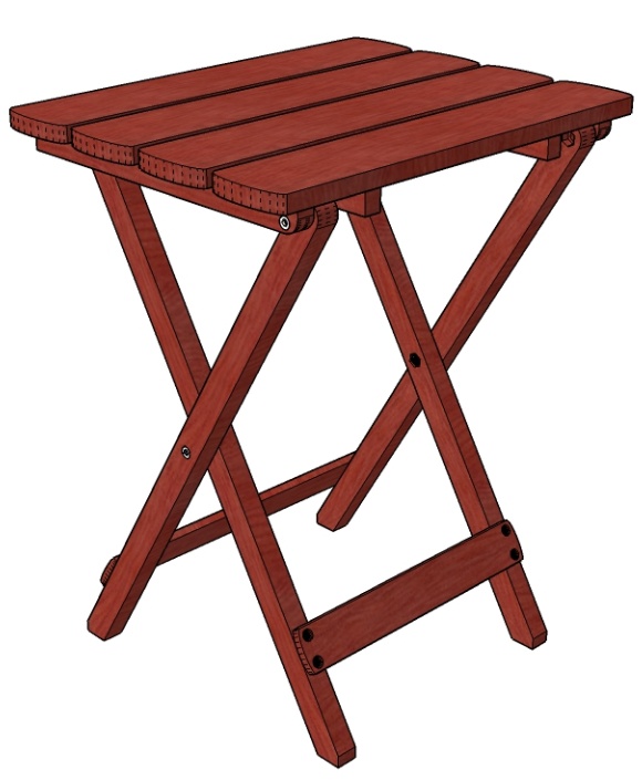
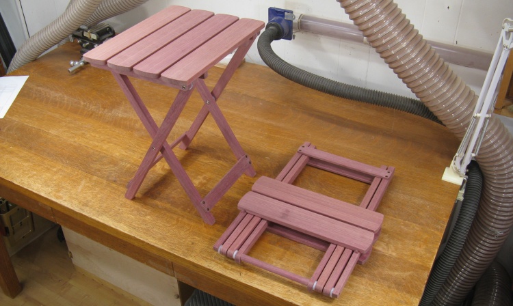
A very similar wood version, but with fewer rivets
Hover to fold/unfold
This little animation shows the existing table folding and unfolding.
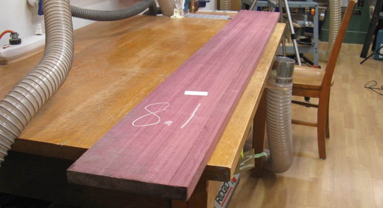
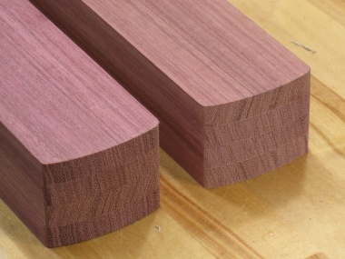
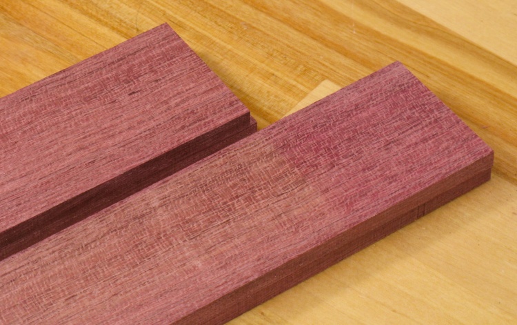
A nice purpleheart plank
Fortunately purpleheart is relatively common and was available at the local Windsor Plywood. It comes from a family of "medium to large" trees with heights of 100 to 170 ft and trunk diameters of 3 ft to 5 ft. That would be a bizzarely large tree in cold cold Saskatchewan but I suppose not unusual in a tropical forest.
As if to emphasize tree size, the planks they had were mostly around 12' in length so I had them cut me a 6' length which was more than enough for two tables. The piece I ended up with was pretty much your ideal plank; consistent thickness and width, no warp or bow and knot-free.
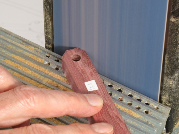
The 8.1 marking refers to the number of board-feet in the original 12' plank.
As if to emphasize tree size, the planks they had were mostly around 12' in length so I had them cut me a 6' length which was more than enough for two tables. The piece I ended up with was pretty much your ideal plank; consistent thickness and width, no warp or bow and knot-free.
The 8.1 marking refers to the number of board-feet in the original 12' plank.
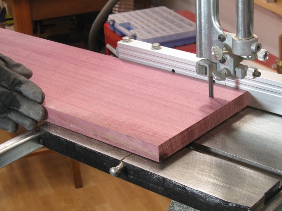
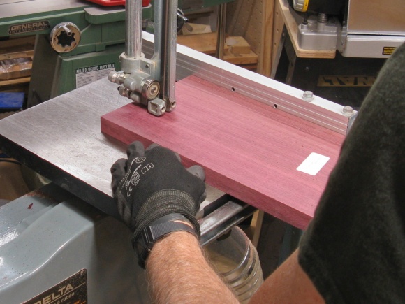
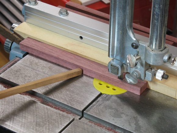
I planned out how to cut the plank size I had into pieces with the minimum wood wastage. Then I got to it with the radial arm saw and the bandsaw. I first cut the plank into sections and then cut pieces out of those smaller sections.
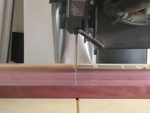
Cutting up the plank
More cutting up the plank

Cutting up the pieces
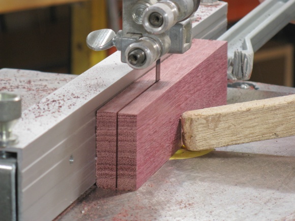
More cutting up the pieces
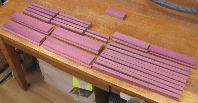
All the pieces rough-cut in the original in-plank arrangement
There are six different shapes of pieces needed for the table and I cut enough for two tables.
The pre-planning of the cutting paid off since the only leftover was that little piece offset from the others.
The pre-planning of the cutting paid off since the only leftover was that little piece offset from the others.
Top
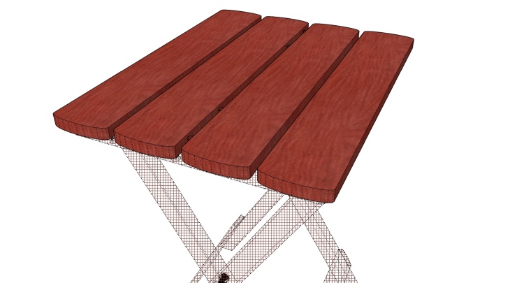
Top pieces highlighted
The top is composed of four planks a touch over a foot long (306 mm for those biunital).
All planks are the same and are also pretty simple, being just flat pieces with rounded ends.
All planks are the same and are also pretty simple, being just flat pieces with rounded ends.

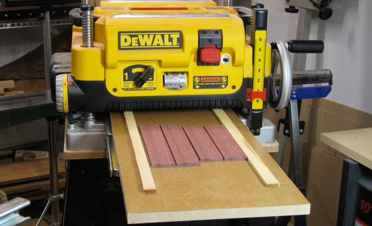
Sanding down to correct thickness
The raw top planks were run through the drum sander to clean up the faces and bring them down to the finished thickness of 11 mm.
After sanding, the planks just needed the ends rounded. I made a couple of taped-together stacks so the ends could be done four at a time. The end curve is an ellipse 6 mm deep and since I needed to mark it a few times, I traced out and cut a business-card pattern to use. Then the ends were marked, cut on the bandsaw and sanded.
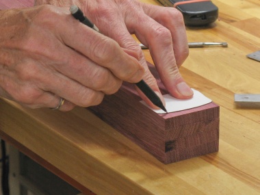
Marking a stack
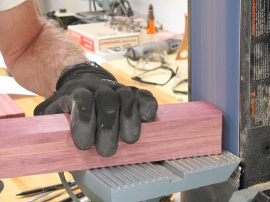
Sanding the cut ends
A couple stacks of top pieces
Sanding all the surfaces with 220 grit
Finally the faces and ends of each top piece were sanded and the corners rounded off, all with 220 grit and at blurry-fast speeds.
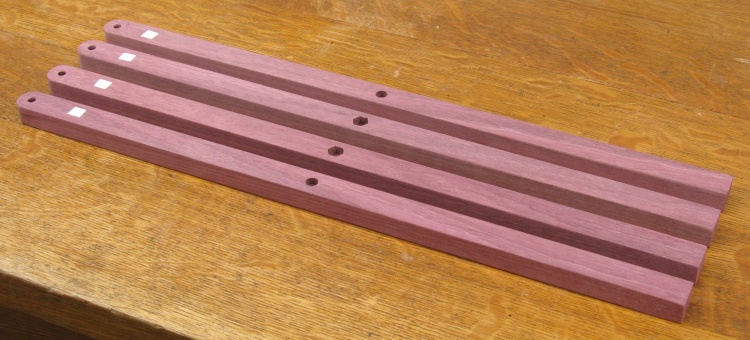
Legs
A set of four legs
In each set of four table legs, the inside legs match as do the outsides (technically one side's legs are mirror images of the other side, but an identical leg can just be rotated 180° to achieve that).
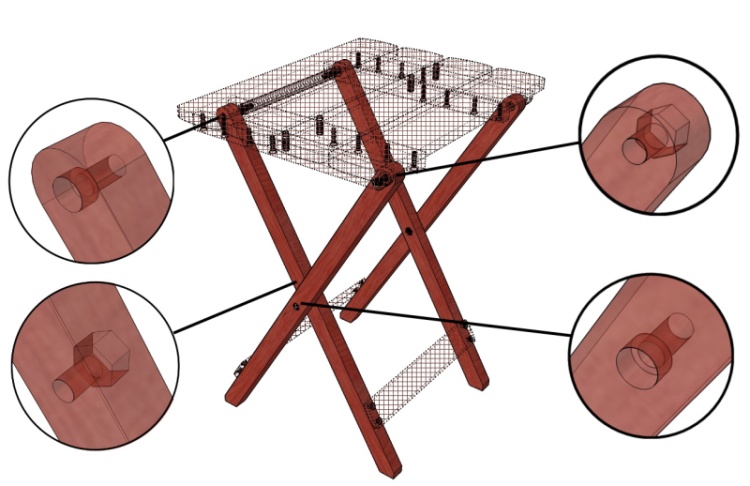
Both types need an embedded bolt-head hole and an embedded-nut hole, although they are in different spots as the diagram shows.
The bolts used are a socket-head cap screw style so the head size is smaller than a regular hexagonal head would be.
Both types need an embedded bolt-head hole and an embedded-nut hole, although they are in different spots as the diagram shows.
The bolts used are a socket-head cap screw style so the head size is smaller than a regular hexagonal head would be.
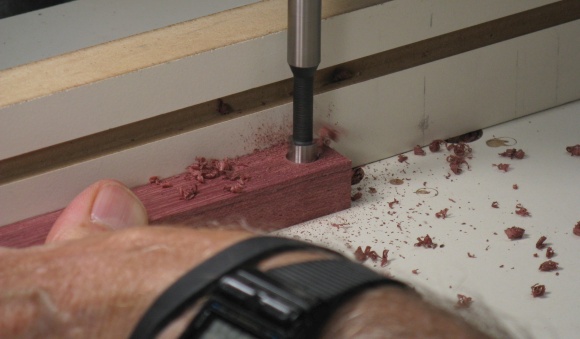
Holes were drilled for the screw head or the nut, followed by a clearance hole for the screw threads.
Drilling the center
...and the end
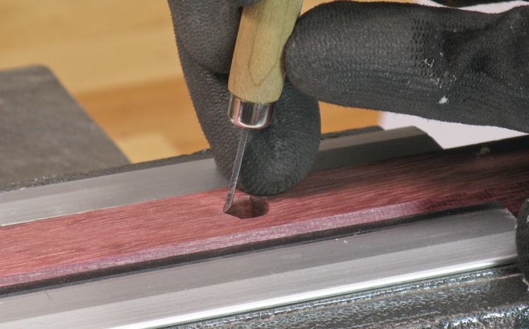
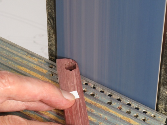
Using a small chisel to change the hole from round to hexagonal
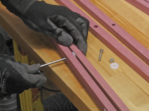
A hexagonal hole was going to be needed to embed the locknuts. The drilled hole was just a bit larger than the flats of the nut so then the 120° corners were formed using a small chisel.
I had first pressed the nut into the hole to make a hexagonal impression as a guide for the chisel.
I had first pressed the nut into the hole to make a hexagonal impression as a guide for the chisel.
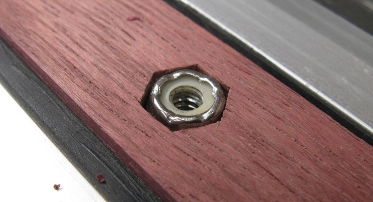
Locknut recessed flush in leg
This shows one of the nuts in place. I used locknuts (sometimes called stopnuts) to prevent to nut from loosening on the screw threads. They achieve this by incorporating a tight nylon washer, visible here crimped into the end of the nut.
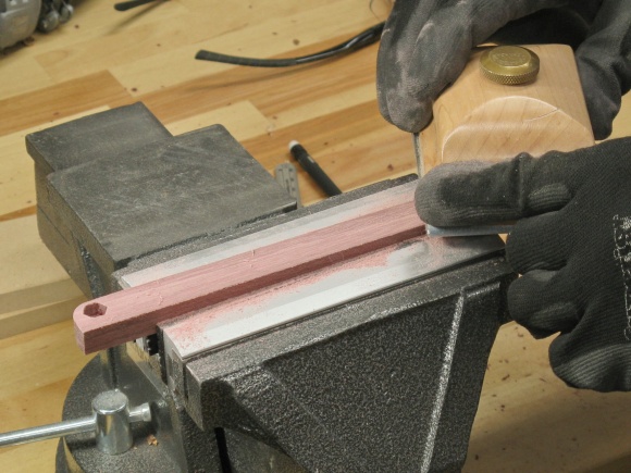
Then the legs just needed the top end rounded and some sanding done.
Rounding the top end

...and then sanding the surfaces and edges
A set of legs for one of the tables
This shot shows a set of legs for one of the tables.
Eventually the bottom ends will need to be cut at an angle, but to do that accurately it will need to wait until after assembly.
Eventually the bottom ends will need to be cut at an angle, but to do that accurately it will need to wait until after assembly.
Joists
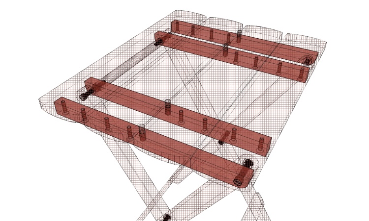
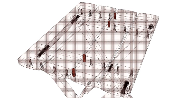
Joists highlighted and shown in X-ray view so holes can be seen
I've used the term "joist" to refer to the four horizontal members supporting the top.
At one end they attach to a leg with a hinged joint and at the other attach to the top pieces with screws.
This highlighted X-ray view reveals the inner secrets of the joists.
At one end they attach to a leg with a hinged joint and at the other attach to the top pieces with screws.
This highlighted X-ray view reveals the inner secrets of the joists.
The joists received similar screw holes to the legs, although only one of the two hole types per joist. Again the holes for the nuts were converted to hexagonality with the aid of a chisel.
Rounding a corner
...and of course the normal surface sanding
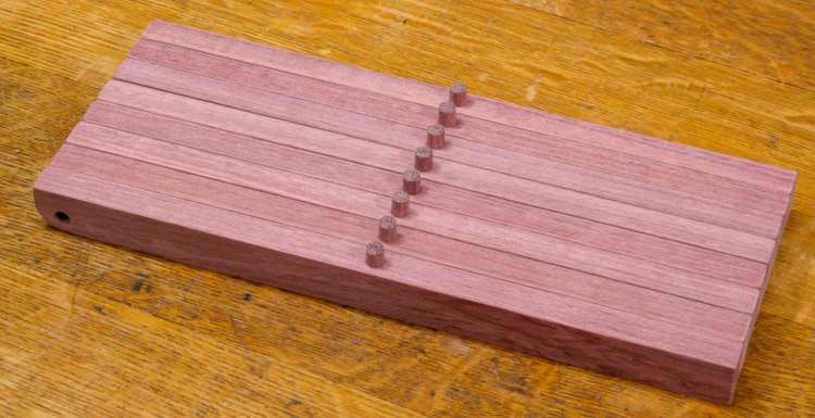
Joists with spacer pins but still needing screw holes
In this shot the joists have the hole for the center pin drilled and a pin installed, although they still need the screw holes.
I realized at this point that unfortunately I'd made all the joists identical; half of them actually needed to be mirror images to work on the other side of the table (and they're not symmetric so I couldn't just rotate them like the table legs). Oops.
I realized at this point that unfortunately I'd made all the joists identical; half of them actually needed to be mirror images to work on the other side of the table (and they're not symmetric so I couldn't just rotate them like the table legs). Oops.
Fortunately I had lots of wood left over so I whipped up another set of joists, this time making sure they were mirror-images of the first ones. Here are a couple shots of me starting my penance.
Cutting a new section
Cutting to size
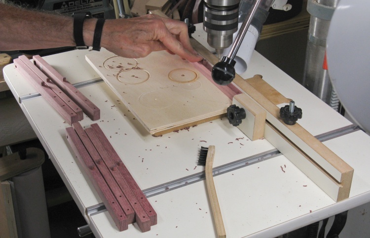
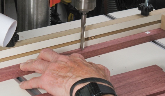
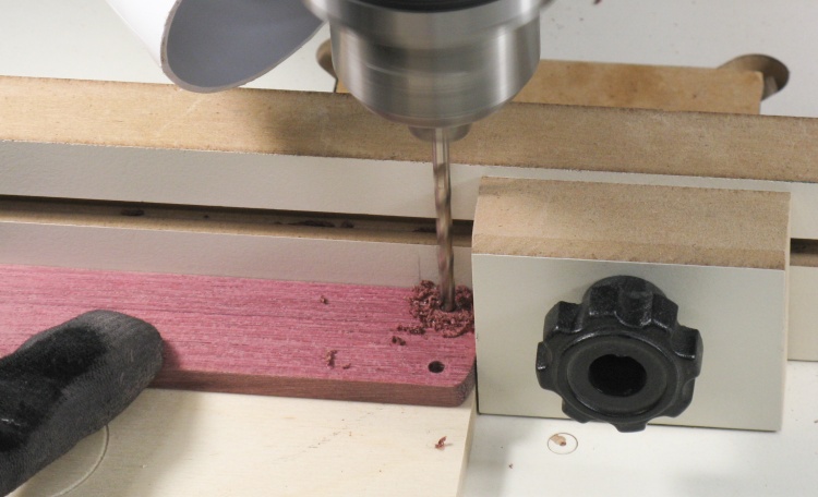
Drilling screw holes in joists
Once my new & improved joists were made, I continued on by drilling holes for the #6 top-mounting screws.
Way more often than you'd expect, taking a photo of the drill press from this side results in a knob exactly blocking the actual drilling operation. You'd think I'd learn...
Way more often than you'd expect, taking a photo of the drill press from this side results in a knob exactly blocking the actual drilling operation. You'd think I'd learn...
Irrelevant
During the (COVID-19) pandemic, of course we weren't going out to restaurants so we would order for delivery instead, using one of the food delivery services (or direct restaurant delivery if available so they weren't screwed out of a large percentage of the price). It usually went fine but sometimes the driver would drop the bag directly in front of the outward-opening front door. Which then couldn't be opened. This led to trying to reach under a partially-open door to move the bag so it wasn't crushed, or a trip through the snow from the back door.
After this happened a couple times I included the delivery instructions: "Place food beside door rather than in front of it please." Unfortunately, while that should be pretty clear I had failed to take into account that the majority of the drivers don't have english as their first language and so it maybe wasn't quite so obvious to all of them. What happened was that some of them would search around (for the "beside door" perhaps?). Sometimes that was the garage door and sometimes they wandered around the house looking for it. I'd usually have to intervene so we could both get on with our lives. I think I'll just get rid of the instructions...
After this happened a couple times I included the delivery instructions: "Place food beside door rather than in front of it please." Unfortunately, while that should be pretty clear I had failed to take into account that the majority of the drivers don't have english as their first language and so it maybe wasn't quite so obvious to all of them. What happened was that some of them would search around (for the "beside door" perhaps?). Sometimes that was the garage door and sometimes they wandered around the house looking for it. I'd usually have to intervene so we could both get on with our lives. I think I'll just get rid of the instructions...
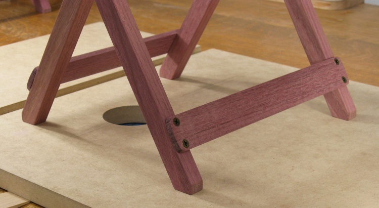
Straps

A pair of leg-stiffening straps
The straps stiffen the table assembly and keep the pair of legs working together.
These are pretty simple rounded-end planks with countersunk holes for the attachment screws.
These are pretty simple rounded-end planks with countersunk holes for the attachment screws.
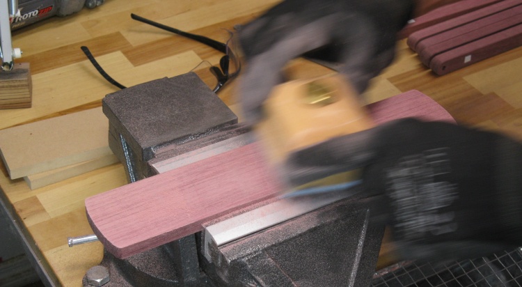
Planing to correct thickness
The rough pieces were planed to the correct thickness using the planer and the anti-snipe sled. I used that instead of the sander since I needed to take off more material.
Some color change over 11 days
The straps sat around for a while as I worked on other bits of the table. When I returned to them, the shorter pieces and the end of the longer piece had a darker red color as compared to covered areas.
Darkening of purpleheart is supposedly due to exposure to UV, although I wouldn't have thought shop lighting would have had much effect. Some woods darken in response to oxygen in the air, so perhaps this was a factor as well.
Darkening of purpleheart is supposedly due to exposure to UV, although I wouldn't have thought shop lighting would have had much effect. Some woods darken in response to oxygen in the air, so perhaps this was a factor as well.
Drilling the screw holes
The straps were:
- cut to the proper width,
- had the ends rounded,
- were drilled as shown, and
- countersinks drilled.
- cut to the proper width,
- had the ends rounded,
- were drilled as shown, and
- countersinks drilled.
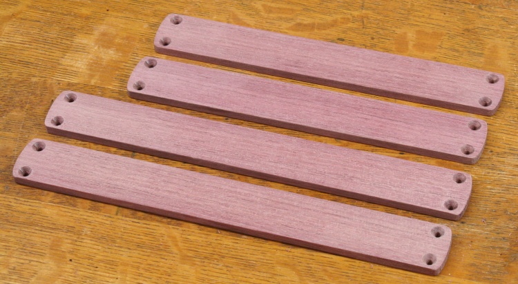
Two sets of straps
Then a bit of surface sanding pretty much finished off the straps.
Handle
The handle highlighted
The handle is just a simple rod spanning the inner joists which ends up at the top of the table in the folded configuration.
The handle provides a handy place to place your, um, hand for, well, handling. Obviously.
The handle provides a handy place to place your, um, hand for, well, handling. Obviously.
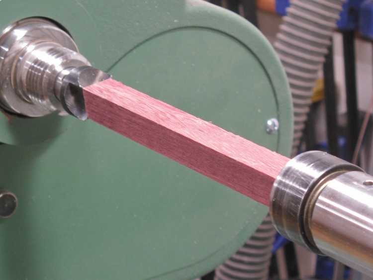
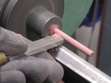
A handle blank on the lathe
A blank was simply rounded on the lathe and then the ends were drilled for screw clearance holes.
This shot shows the square-sectioned blank ready to start.
This shot shows the square-sectioned blank ready to start.
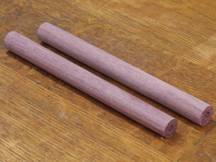
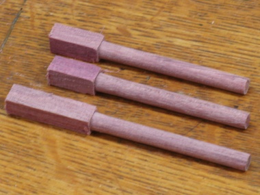
A couple of handles ready to go
The pair of completed handles.
Spacing Pegs
The four spacing pegs shown
The table top is composed of two separate pieces which slide together with the planks of each half sitting on the joists of the other half. Spacing pegs positioned in the centers of the joists maintain the plank spacing between the table top halves.
The spacing pegs were pretty easy; it was just a matter of rounding a blank to a 6 mm diameter and cutting them to length.
A little blank in the lathe
Rounded off
Enough for the 8 pegs needed

Rounding the top with a couple of power tools
After cutting the pegs to length, I rounded off the tops slightly using a cordless drill in combination with the belt sander, followed by some hand sanding.

The 8 pegs (plus one fuzzy spare way in the back)
The completed pegs.
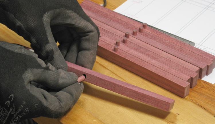
Inserting the pegs into the joists
I had only Imperial drill bits so in the joists I drilled a 15/64" hole which at 5.95 mm was very slightly too small for the 6 mm pegs (well 6 mm +/- 0.1 mm). So I used an abrasive bit to slightly enlarge each of the holes until it fit a peg tightly.
It might have made sense to have turned the pegs to 15/64" instead of 6 mm but apparently I failed to think that far ahead (like, a hour) that day.
On the other hand, each peg was custom fitted and sat snugly in the hole, so I didn't even bother to glue them in.
It might have made sense to have turned the pegs to 15/64" instead of 6 mm but apparently I failed to think that far ahead (like, a hour) that day.
On the other hand, each peg was custom fitted and sat snugly in the hole, so I didn't even bother to glue them in.
Washers
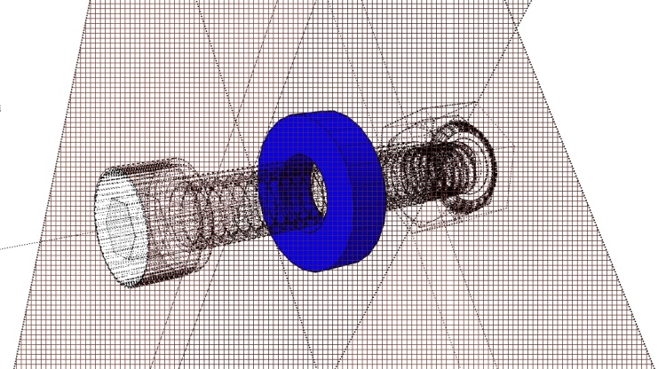
An unrealistically-coloured washer
All of the joints in the table need to be able to rotate smoothly for the folding/unfolding process. The washers provide low-friction bearing surfaces and also establish spacing between the adjacent parts to prevent any rubbing in the case of slight warpage or imperfect parallelism.
The original table used large plastic washers so I largely replicated that in the wooden version.
These are not standard-sized washers nor standard washer material so I needed to "roll my own".
The original table used large plastic washers so I largely replicated that in the wooden version.
These are not standard-sized washers nor standard washer material so I needed to "roll my own".
Cutting out a piece of 3/4" plastic
The washers are 3/4" diameter and 3 mm thick (sorry about the unit clash) and I had some suitable polyethylene to use for them.
I started by cutting a 3/4"-square blank on the bandsaw.
I started by cutting a 3/4"-square blank on the bandsaw.
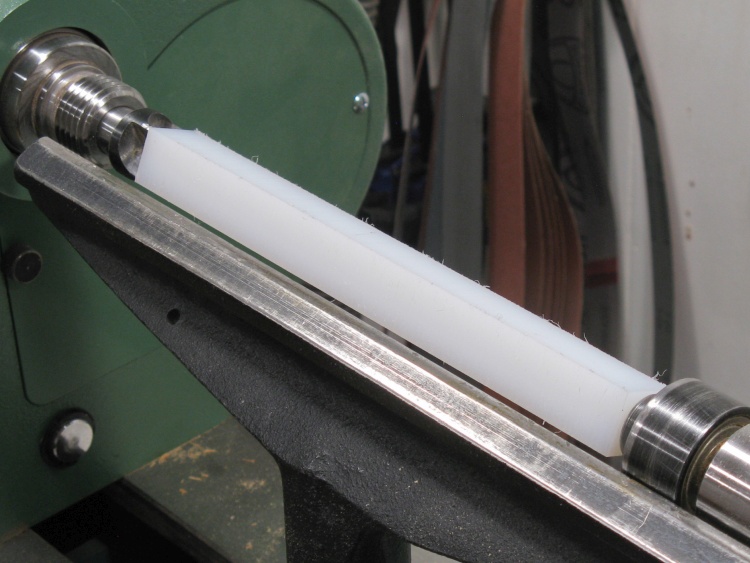
Half that plastic on the lathe
The piece I cut off was long enough to be wobbly on the lathe so I chopped it in half and mounted that to the lathe. As it turned out, that was enough to do all the washers.
Here it is mounted between centers. After this shot I rounded it off to a roughly consistent 3/4" diameter.
Here it is mounted between centers. After this shot I rounded it off to a roughly consistent 3/4" diameter.
Then I needed to get from cylinder to washer which involved drilling the clearance hole for the bolts and then cutting off appropriate lengths. For the cutting, I marked the 3 mm length needed, then used a makeshift parting tool composed of a small scraper blade held with Vise-Grips.
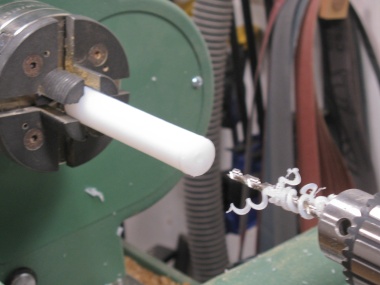
Rounded and drilled
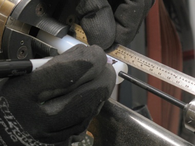
Marking length of one washer (3mm)
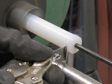
Cutting off a washer
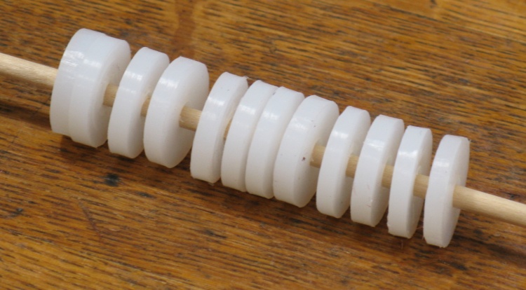
The complete set of washers
After a bit of edge cleanup, the 12 washers were ready to go.
Assembly
The (next to) last step was assembly. These X-ray diagrams show the three types of joints formed by #10-24 bolts with locknuts. I wanted any exposed ends of the bolts to be flush. A 1" bolt worked out just right on the first joint, I used a 1-1/2" for the next joint (where the extra length wasn't critical) and I cut a bolt off to 33 mm length for the last joint.
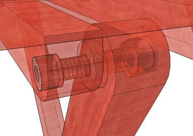
Outside top joint
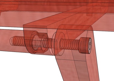
Inside top joint
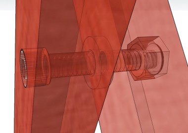
Center (leg) joint
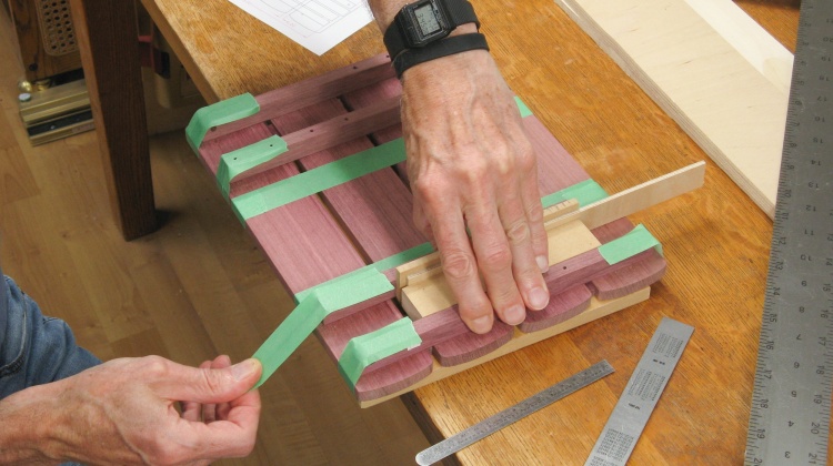
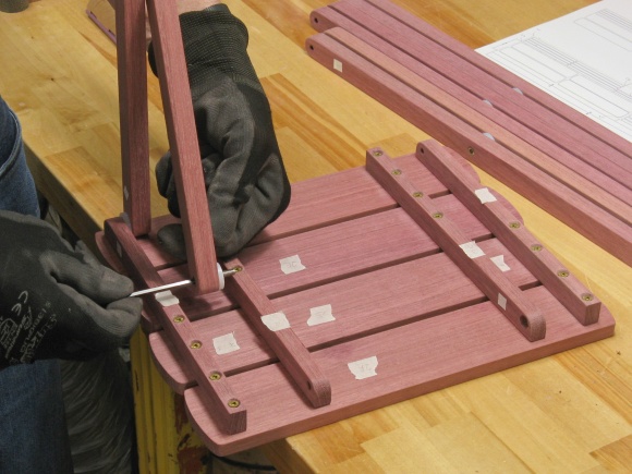
Taping together tops and joists for drilling
I started assembly by attaching the joists to the top planks. In order to get proper alignment, the two top halves were made in the same step.
The top planks were first taped to a backing board with 6 mm spacers between them to provide proper plank separation. in this shot the joists have been positioned on top of the planks and I'm taping them down as well. The plan is to use the joist screw holes as a guide to drill pilot holes in the top planks.
The top planks were first taped to a backing board with 6 mm spacers between them to provide proper plank separation. in this shot the joists have been positioned on top of the planks and I'm taping them down as well. The plan is to use the joist screw holes as a guide to drill pilot holes in the top planks.
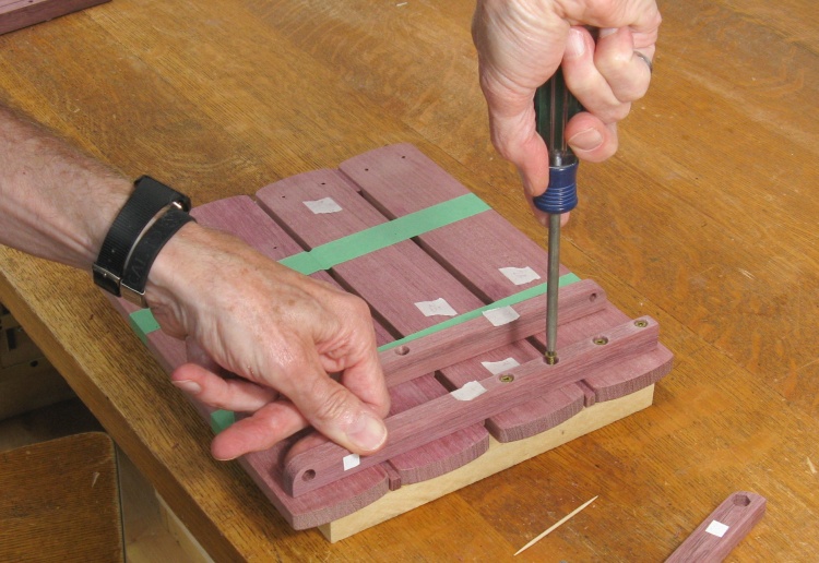
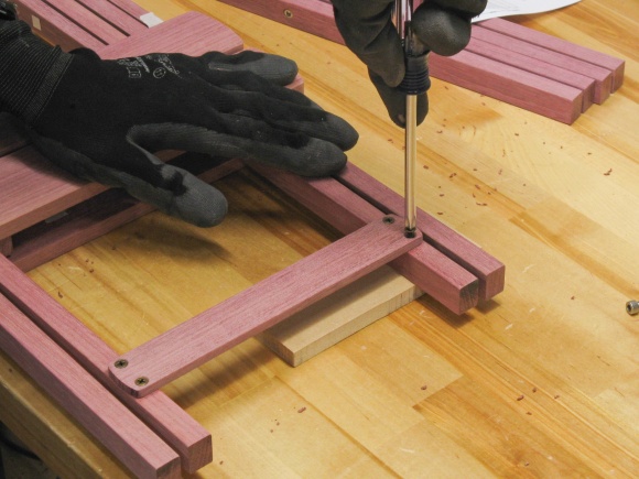
Screwing a joist to a top section
After drilling screw pilot holes partway through the top planks, I redrilled the joists with clearance-sized holes and put countersinks on the joist bottoms as well.
Then in this shot, I'm starting to screw the joists to the top planks with brass wood screws.
Then in this shot, I'm starting to screw the joists to the top planks with brass wood screws.
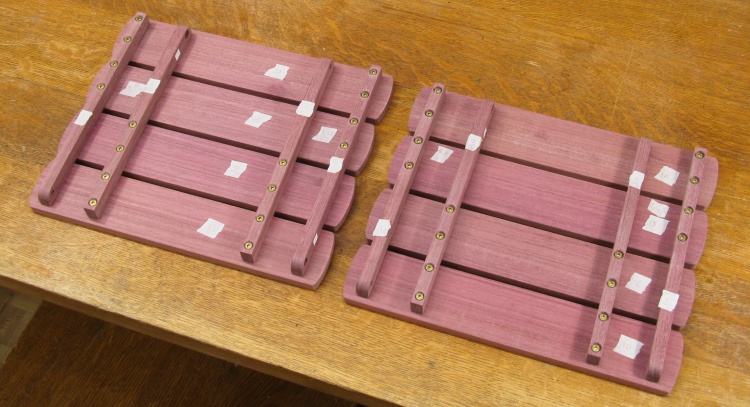
Two pairs of top assemblies
This photo shows both completed tops. Each is actually composed of two separate pieces but they have been overlapped like they will be in the actual table.
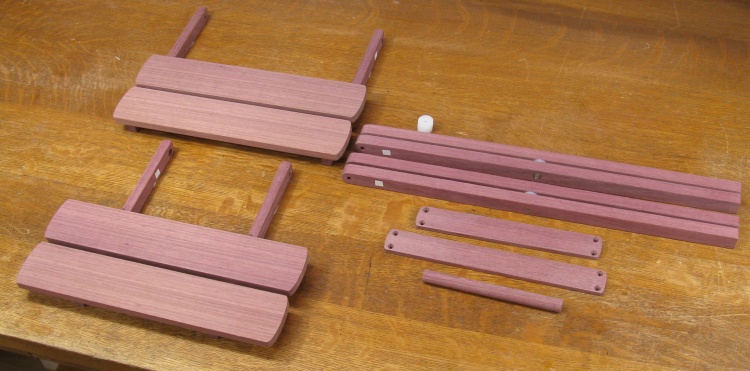
A semi-assembled table
This shows all the pieces needed for a single table, with assembly already started on tops and legs.
I started by assembling pairs of legs. As with all the joints, they have a #10 socket-head bolt, a plastic washer and a hex locknut. Following that, the legs were attached to the overlapped top assemblies.
Leg joint
Starting an inside joint
The inner legs attached with longer screws that extended into the handles to hold them in place. Finally the straps were screwed into the legs.
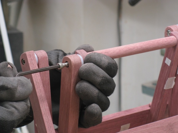
Finishing the inside joint
Adding the leg straps
Ready to cut leg ends
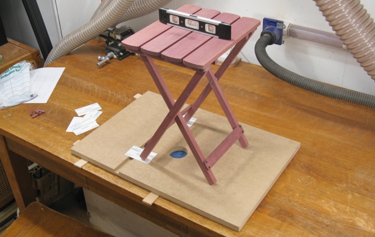
Once the tables were assembled, I could look at cutting those square leg bottoms to the correct angle.
I started by using a flat sheet of wood as a base which I shimmed up to be level. Then I set the table on top and shimmed the legs until it was level as well.
I started by using a flat sheet of wood as a base which I shimmed up to be level. Then I set the table on top and shimmed the legs until it was level as well.
Done
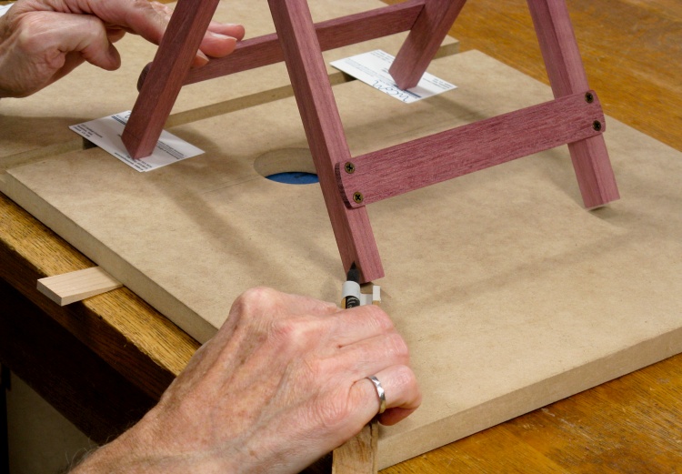
The next step was to mark all four legs with a line at the same distance above the base which was just done using a pencil taped to a square piece of wood.
So when the legs are cut at the lines, all four should just exactly touch the base and voilà - no wobble*.
*Of course almost anywhere I set the table could be non-flat which would produce a wobble. But at least I'll know it wasn't the table's fault.
So when the legs are cut at the lines, all four should just exactly touch the base and voilà - no wobble*.
*Of course almost anywhere I set the table could be non-flat which would produce a wobble. But at least I'll know it wasn't the table's fault.
The legs were removed from the tables for easier handling and I set up the bandsaw mitre gauge at the appropriate angle (58.5°, thanks for asking) and cut them to the line. That was followed by sanding a bevel into the sharp corner.
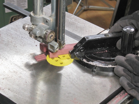
Cutting to the line
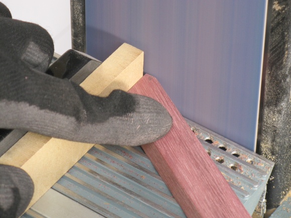
Making a bevel
Done
And sure enough, all four legs sat nice and flat on the base when done.
Done
This shows the pair of completed tables.
I had decided to avoid adding a finish since pretty much anything would need to be renewed periodically. My policy is a low-maintenance yard so that would be incompatible with mylaziness principles. I'll see how these survive our summers. If worst comes to worst I can pull them apart, sand them smooth and add a finish in the future.
I had decided to avoid adding a finish since pretty much anything would need to be renewed periodically. My policy is a low-maintenance yard so that would be incompatible with my
Done
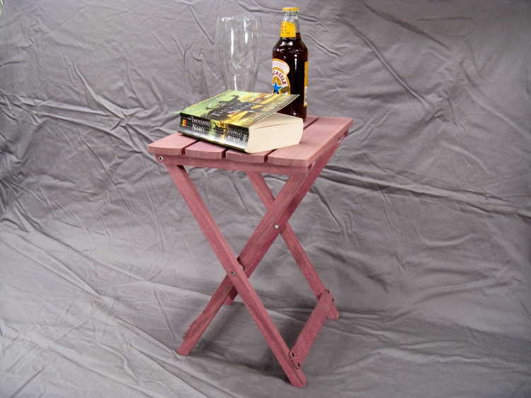
This shot shows one of the tables in the "summer configuration".


