I figured that a leg-less, turned table design should be pretty straightforward to make, so I drew up some plans that accommodated the sizes of wood I had available. The most significant limitation was the 2" thickness of what would be used for the main vertical shaft. Some extra pieces in the other grain orientation at top and bottom gave a larger diameter to help to make the rather thin vertical shaft less spindly-looking.

The table, so tall I had to stack two virtual rulers
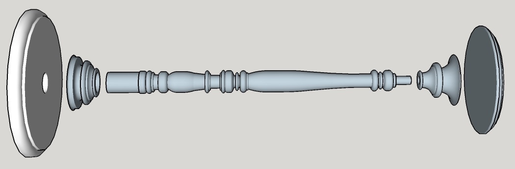
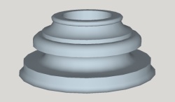
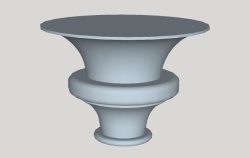
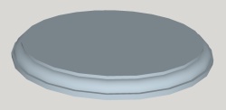
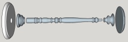
An exploded view showing the table components
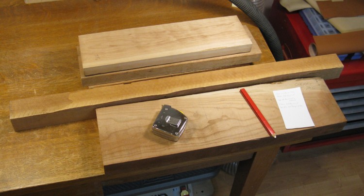
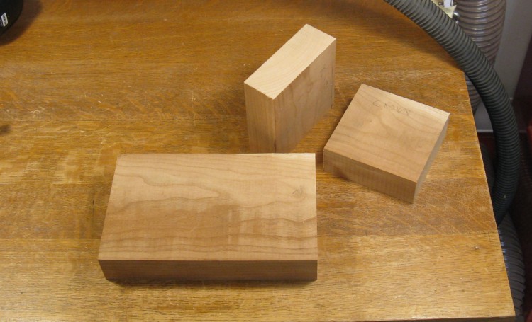
A decent selection of Cherry
Just for fun, I later made up a 3D drawing of the table components, shown above in the classic "exploded view".
I actually had a reasonable number of cherry pieces left over from various past projects and even had some extras so I was able to pick and choose the ones I wanted to use.
This little collection was enough for the table.
I actually had a reasonable number of cherry pieces left over from various past projects and even had some extras so I was able to pick and choose the ones I wanted to use.
This little collection was enough for the table.
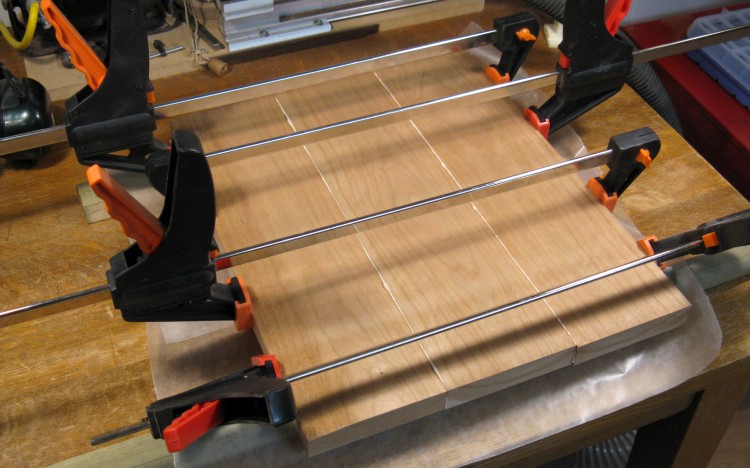
Clamping pieces for the base
1. Base
I began at the bottom - which meant the table base - and worked my way up.
For the base, I started by laminating together the three 1"-thick planks seen in the background above to make a blank large enough for the 12"-diameter base.
Here the wood has been jointed and planed on the surfaces for flatness, jointed again on the edges for straightness, glued and clamped.
For the base, I started by laminating together the three 1"-thick planks seen in the background above to make a blank large enough for the 12"-diameter base.
Here the wood has been jointed and planed on the surfaces for flatness, jointed again on the edges for straightness, glued and clamped.
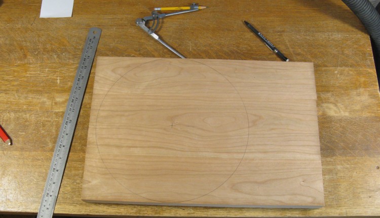
Base outline marked
After the glue was dry, the blank was run through the planer again to even up the faces. Here, the base circle has been pencilled in using my big definitely-not-from-a-geometry-kit compass.
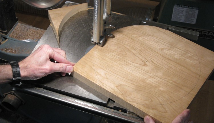
Cutting out the base
I did a freehand cut on the bandsaw to form the circular base, cutting just a bit outside the line.
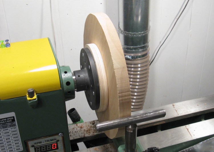
Base on the lathe, ready to be rounded
The base was mounted to a circular piece of plywood using double-sided tape. The plywood in turn was held to the large metal faceplate with a half-dozen screws. This gave a secure mount, but the tape allowed the base to be pried off when it was done, theoretically unmarred.
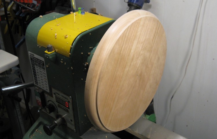
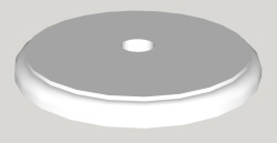
Shaping & sanding the base is done
The whole rounding/edging thing could also have been done using a router setup, but since I was doing a "turning" project, it was just done on the lathe. The results were probably better as well.
In this photo the rounding, edge shaping and sanding has been done.
In this photo the rounding, edge shaping and sanding has been done.
Pieces for the plinth, crown and top
2. Plinth
The 2"-thick plank was cut up into these three pieces. The larger one will be cut into two thinner pieces to be laminated together for the top while the other two will be used for the plinth and crown.
Plinth and crown blanks
The plinth and crown pieces were trimmed to something (slightly) closer to circular as shown here.

Starting to turn the plinth
I started with the plinth, which like the base was taped to a piece of wood and screwed to a faceplate. Here the turning has started, with the bottom part mostly done having produced lots of apparently static-y wood shavings.
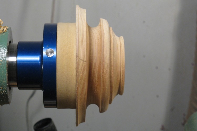
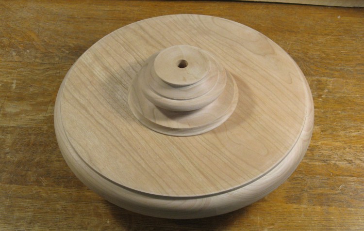
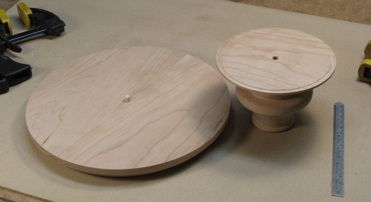
Completed plinth profile
This shows the profile of the completed plinth.
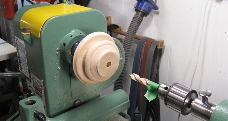
Drilling to mark the center
The plinth needed to be mounted and centered on the base and it would also need a large central hole to accept the end of the spindle. These were both facilitated by drilling a 1/2" hole on the lathe as shown here.
The hole actually went all the way through the plinth, contrary to what the masking-tape-depth-marker on the drill bit might imply.
The hole actually went all the way through the plinth, contrary to what the masking-tape-depth-marker on the drill bit might imply.
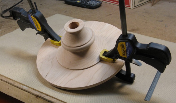
Plinth glued to the base
The central hole in the plinth made it straightforward to align it with a center mark on the base and here the pieces have been glued together.
It is sitting a bit off the table since I left on the wooden piece taped to base to be able to re-mount it to the lathe.
It is sitting a bit off the table since I left on the wooden piece taped to base to be able to re-mount it to the lathe.

Enlarged hole to fit spindle
The base assembly went back on the lathe so the central hole could be enlarged to accept the bottom of the spindle. The hole also extended about 3/4" into the base for additional strength.

A bit of practice before I work on the real piece
3. Spindle

I had made spindles in the past, but my skills were...rusty, let's say. I figured I should get a bit of practice under my belt before moving on to the one piece of wood I had for the spindle. So I pulled out an old table leg, rounded it off and set to practice with the skew chisel.
Now the skew chisel is a dangerous tool. Dangerous to the wood, anyway. It has a knife-like blade that must go into the wood at an angle and if not done just right, is pulled along at high speed to cut an involuntary spiral just where you don't want it. There's a chewed-up looking section just at the left end of the tool rest where exactly that happened.
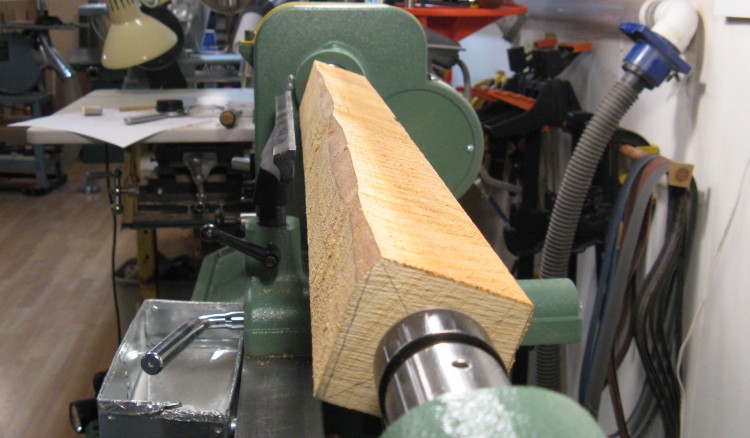
and now...the real piece
Eventually I managed to make a few successful beads with sharp notches between them and figured I better switch over to the real piece while I was hot.
Here the 2x2" piece for the spindle is mounted on the lathe. The wood wasn't perfectly straight, but that would get fixed in the rounding-off process.
Here the 2x2" piece for the spindle is mounted on the lathe. The wood wasn't perfectly straight, but that would get fixed in the rounding-off process.
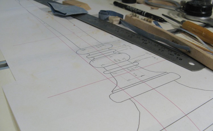
The full-sized plan for reference
I usually print out a full-sized plan to work with - in this case four 8-1/2 x 11 sheets taped together. It's actually a bit surprising how accurate the printer is - I always find that the plans are bang-on size-wise.
Here the plan is sitting on my large drill press table and I've made measurements and marked them in pencil to help guide the turning.
Here the plan is sitting on my large drill press table and I've made measurements and marked them in pencil to help guide the turning.
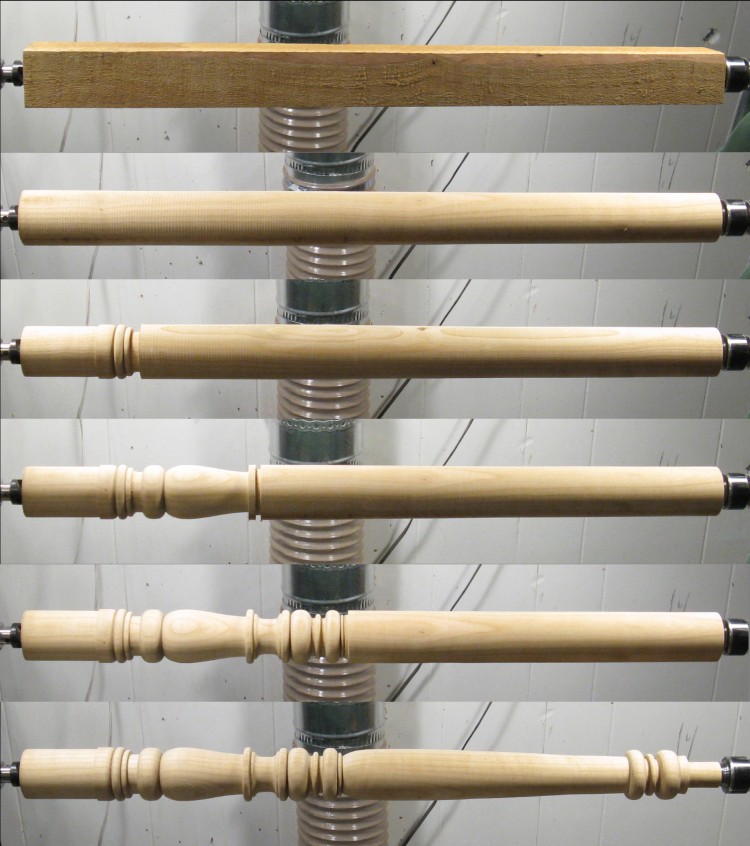
The classic turning composite
This montage shows the shaping progress starting with the square-cross-sectioned wood blank.
First step was to round it off. I cut off the minimum amount possible so I'd be left with the largest diameter I could get.
I started with the straight section that goes into the plinth and base, and then the first couple of beads.
Then I just progressed from left to right adding features as I went.
...until it was done, including another straight section on the right for mating with the top.

Completed spindle from a more jazzy angle
This shows the completed spindle after sanding to smooth off any remaining tool marks.
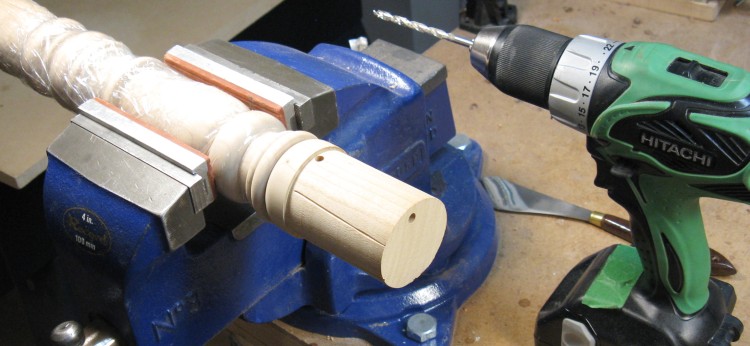
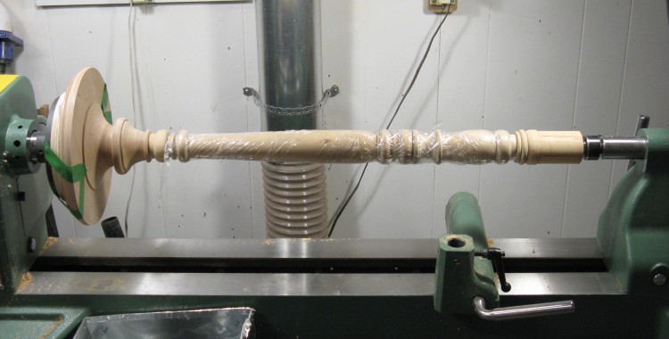
Adding a vent to the spindle bottom
When gluing a round shape in a matching hole, the glue tends to form an airtight seal. This isn't a problem if the other end of the hole is open, but if the hole has a sealed bottom then there is nowhere for the air to escape and it just gets compressed. This prevents full insertion and also pushes the piece back out.
To prevent this I drilled a vent path up the spindle and out to the side. The air can come escape this route and prevent the problem. This photo shows the vent hole. You might notice that body of the spindle is wrapped in plastic. This is to prevent skin oils from getting onto the wood before the finish is applied.
To prevent this I drilled a vent path up the spindle and out to the side. The air can come escape this route and prevent the problem. This photo shows the vent hole. You might notice that body of the spindle is wrapped in plastic. This is to prevent skin oils from getting onto the wood before the finish is applied.
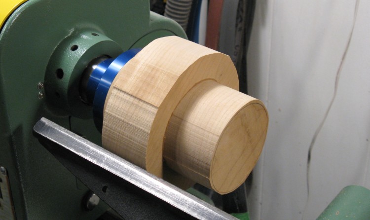
The blank for the crown ready to turn
4. Crown
Moving on upwards through the table components, the next piece is the crown. This photo shows the round blank previously cut for it, with another smaller piece glued on for additional thickness. Here it awaits the attention of the turning tools.
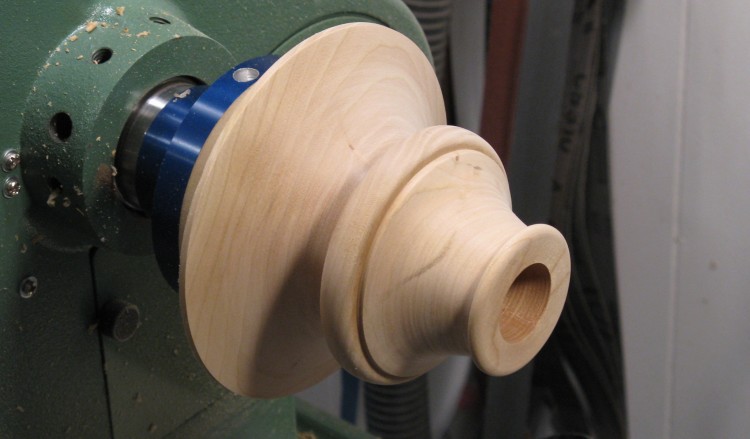
Completed crown piece
...and after that bit of attention (plus some sanding), this is the result. The wide part will mount to the underside of the table top and the hole will accept the dowel formed into the top of the spindle.
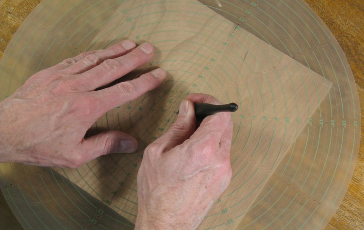
Finding the center of the top blank
5. Top
The last remaining piece is the actual table top.
The larger of the 2"-thick pieces of wood shown previously was cut into two thinner pieces and glued together edge-to-edge to form a blank large enough for the 10"-diameter top.
In this photo, I'm using a concentric-circle overlay to find and mark the center of the wood before mounting it on the faceplate.
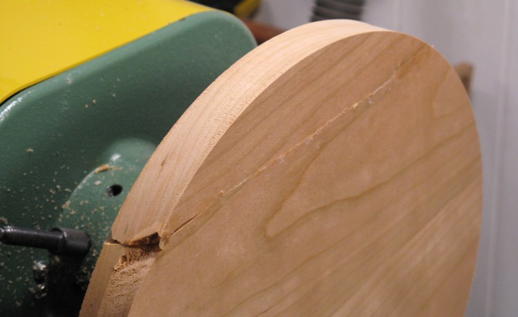
A top "oopsie" after being glued back together
After cutting into a circular shape and taping to the faceplate, I started by truing up the edges.
This shot is the aftermath of using the wrong tool (yes, the dangerous skew chisel), or perhaps using it at the wrong angle, or perhaps just random bad luck. But the effect was to have the tool dig into the wood, chew off a 1.5" section and throw it across the room (all in about 1 millisecond if my recollection is accurate). I figured I'd need to restart with a new piece of wood, but I was just heading out of the house, so I slapped the piece back into place and glued it on in case I could recover this piece.
This photo shows the site of the gouge and the reattached piece after the glue had dried.
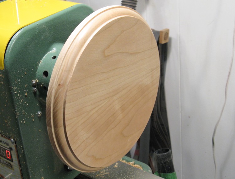
Top done. Can you spot the oopsie?
I'd made the wood a bit oversized, so I was able to reduce the diameter to get past the edge trauma seen in the previous photo. This ended up leaving the top about 1/2" smaller than I'd planned, but that still looked fine.
In this photo, the top has been reduced in diameter and the edges have been shaped. A bit of coarse surface sanding was done to remove the glue and even-up the split piece, which is why the grain is not exactly the same as the previous photo. The split is pretty much invisible in this shot. It can actually be detected on a close visual inspection of the edge but fortunately that's tough to do when it has a big fern on it...
In this photo, the top has been reduced in diameter and the edges have been shaped. A bit of coarse surface sanding was done to remove the glue and even-up the split piece, which is why the grain is not exactly the same as the previous photo. The split is pretty much invisible in this shot. It can actually be detected on a close visual inspection of the edge but fortunately that's tough to do when it has a big fern on it...
Top parts ready to go together
6. Assembly
With all the parts made, it was time to start putting things together.
I already had the base and plinth assembled, and I'd found that the lubricant effect of the glue (where the pieces slide against one another when clamp pressure is applied) was a major problem. I'd had to clamp on pieces of wood to the base around the plinth to keep it in place.
The avoid a repeat of that on this assembly, I added a small locating dowel that tied the crown and top together.
Top parts glued & clamped
Then the glue and clamps were added with no tendency for the pieces to move.
Also visible in the previous photo is a shallow trench carved around the edge of the plinth top, planned to reduce the liklihood of glue squeeze-out. Whether because of this brilliant innovation or just using the right amount of glue, there wasn't any squeeze-out issue.
Also visible in the previous photo is a shallow trench carved around the edge of the plinth top, planned to reduce the liklihood of glue squeeze-out. Whether because of this brilliant innovation or just using the right amount of glue, there wasn't any squeeze-out issue.
Gluing in spindle using the lathe as a big clamp
The next step was to glue the spindle into the tabletop assembly. I had also drilled a vent hole on the top of the spindle similar to what was done on the bottom to prevent problems.
I wanted to ensure the top was correctly square to the spindle, so I used the lathe as a clamp. It has the large faceplate on one end which is exactly square to the axis of the lathe, and I put the live center into the middle of the spindle bottom so it was exactly on the axis.
I wanted to ensure the top was correctly square to the spindle, so I used the lathe as a clamp. It has the large faceplate on one end which is exactly square to the axis of the lathe, and I put the live center into the middle of the spindle bottom so it was exactly on the axis.

Top parts joined to bottom parts
With that done, the last bit was to put the spindle/top assembly into the base.
I found the assembly was pretty straight when free-standing, and it didn't really need clamping. I just levelled the supporting surface and ensured the top remained level using, well, the level.
I found the assembly was pretty straight when free-standing, and it didn't really need clamping. I just levelled the supporting surface and ensured the top remained level using, well, the level.
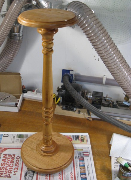
The first coat of varnish applied
This photo shows the completed table with the first coat of varnish. I used my new favorite, a wipe-on Miniwax Fast-Drying Polyeurethane. It received three coats all told.

Done


