Of course there were no actual tablet holders on the market, much less one in the right size. I thought making one would be a fairly simple project, but it ended up taking a bit of time since it extended across the non-woodworking season (AKA summer). I got back to it the next season but my odd design took a while to finish off due to lots of sanding and shaping.
The theory was that it would sit between the chairs (the leathery-colored outlines shown in the plan) and hold the tablet just below the chair arm height. It was designed to have a curious main body, a funky base, offbeat feet and a peculiar holder. Does it work? And with adjectives like that, does it even need to?
The theory was that it would sit between the chairs (the leathery-colored outlines shown in the plan) and hold the tablet just below the chair arm height. It was designed to have a curious main body, a funky base, offbeat feet and a peculiar holder. Does it work? And with adjectives like that, does it even need to?
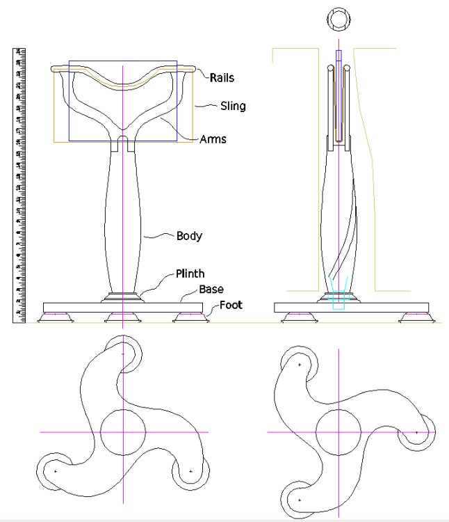
Plan, annotated
1. Body
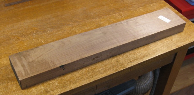
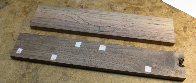
Starting point for the body
I started with the body, which seemed like it would be the most involved part. It needed a 4"-square piece to start with, which came from laminating two 2" pieces.
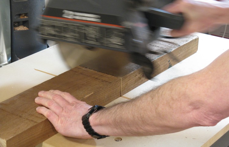
Making two pieces
My original plank was sawn in two - really fast!
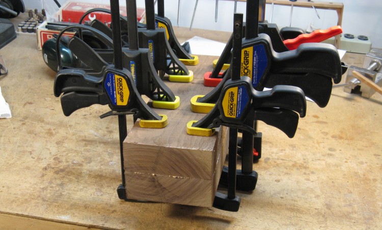
Gluing the body blank
After jointing the facing sides to flatten them, the two pieces were glued together, shown here being clamped while the glue sets.
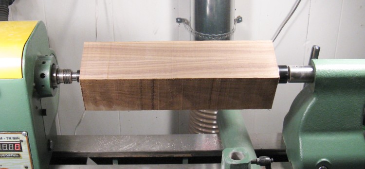
Body blank cut to size and on the lathe
The above assembly was a bit wide, so it was cut to the proper width and mounted on the lathe.
On the driving end on the left is a "spur center" which just like it says on the box has spurs that bite into the wood for good grip. And on the right is a "live center" which is a free-spinning bearing with a central point. Perhaps unsurprisingly, this arrangement is called "turning between centers".
On the driving end on the left is a "spur center" which just like it says on the box has spurs that bite into the wood for good grip. And on the right is a "live center" which is a free-spinning bearing with a central point. Perhaps unsurprisingly, this arrangement is called "turning between centers".
Rounding
The roughing gouge was used to round off the blank. This process generates lots of chips and the gouge directs them upwards and outwards. I always need to vaccuum and sweep after doing the roughing stage since the floor is covered in wood chips all around the lathe.
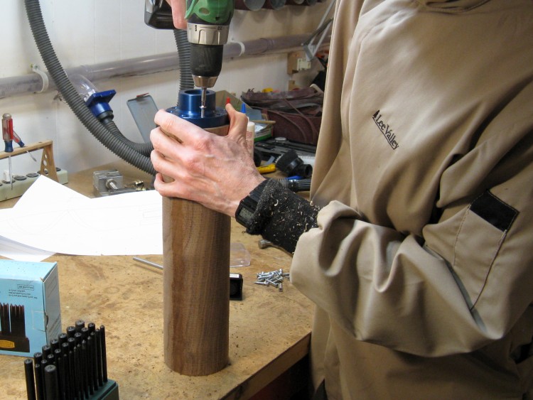
Screwing on the faceplate
When the rounding was complete and the end trued up, it came off the lathe to have a small faceplate attached.
The screws holding the faceplate obviously interfere with any woodturning in the region of the baseplate, so the blank has extra length for this.
The screws holding the faceplate obviously interfere with any woodturning in the region of the baseplate, so the blank has extra length for this.
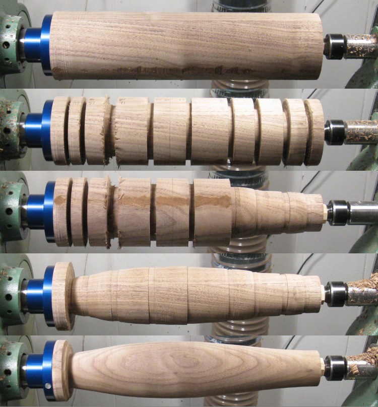
Shaping montage
This montage shows the shaping progress starting with the smooth blank.
A parting tool was used to cut to the measured diameter at several spots along the length.
And this is the beginning of the excess wood being cut away, starting at the top of the body.
Here it's mostly down to the desired diameters but still rather lumpy.
And then after some smoothing work with scrapers the final shape is achieved.
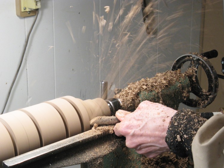
Some of the shaping in action
Here's an action shot of some of the shaping using a bowl gouge. It can remove wood pretty quickly as suggested by the chip fountain in the photo.
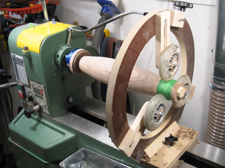
Remounted for hollowing
Next I looked at hollowing the body. For this, I pulled of the tailstock and added the steady rest to be able to get at the end. The green tape holds down a thin plastic strip wrapped around the wood to prevent damage from the wheels.
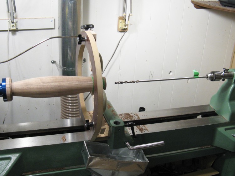
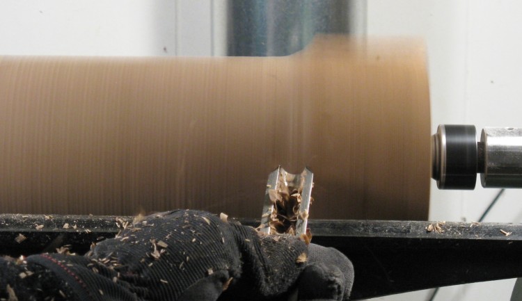
Set up to drill the pilot hole
The first step was to drill a pilot hole as a starting point for the hollowing.
In hollowing something like a vase, the depth of the drill hole would mark the inside depth. However, this one will be hollow through and through, so I used my longest drill bit to be able to drill right through the other end. The blue faceplate has a hole in the center to accommodate this.
In hollowing something like a vase, the depth of the drill hole would mark the inside depth. However, this one will be hollow through and through, so I used my longest drill bit to be able to drill right through the other end. The blue faceplate has a hole in the center to accommodate this.
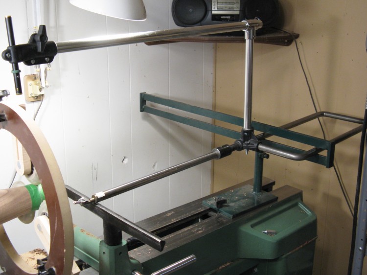
Hollowing jig is ready to go
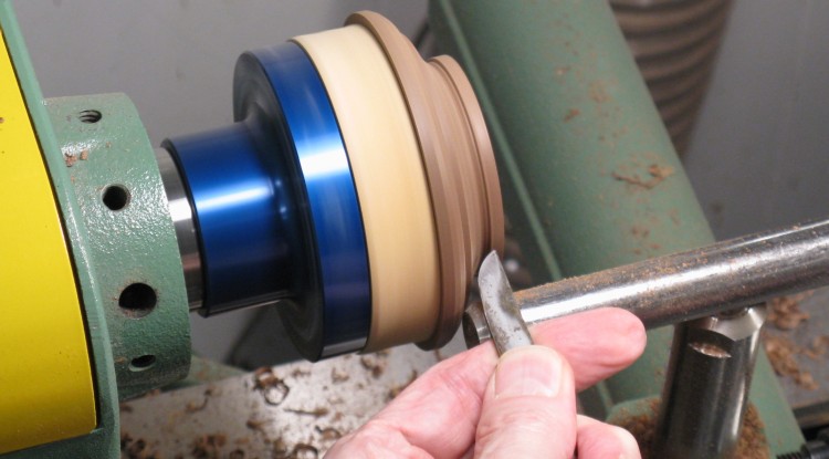
Here's a shot of the hollowing tool I usually use, with the little cutter sitting on the tool rest and the laser that marks its position on the separate arm overhead.
And here's a bit of trivia you may not want to know. There is a thick green ring visible on the laser body just above the tiny copper-colored power button. The button needs to be continuously depressed to keep the laser on, so the rubber ring is rolled over the button to hold it in, and rolled back off again to turn it off. It came with the laser. And now the trivia; the ring is an elastrator; a tight latex ring used mostly for livestock castration. "Oh, right" say the people who grew up on a farm. "Ewww" say the city folks...
And here's a bit of trivia you may not want to know. There is a thick green ring visible on the laser body just above the tiny copper-colored power button. The button needs to be continuously depressed to keep the laser on, so the rubber ring is rolled over the button to hold it in, and rolled back off again to turn it off. It came with the laser. And now the trivia; the ring is an elastrator; a tight latex ring used mostly for livestock castration. "Oh, right" say the people who grew up on a farm. "Ewww" say the city folks...
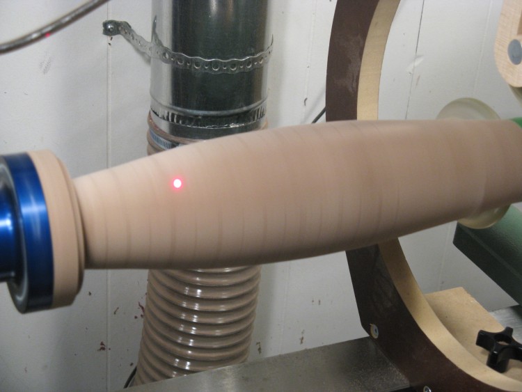
Laser showing hollowing is almost to the bottom
Here I'm standing past the right side of the photo guiding the hollowing jig. The laser spot corresponds to the position of the cutter so you can see that it is most of the way to the bottom.
It's possible to see faint lines around the wood. These are images of dark pencil marks on a strip of tape that runs from end to end. I used the position of the laser spot relative to the lines to judge the progress of the cutting bit.
It's possible to see faint lines around the wood. These are images of dark pencil marks on a strip of tape that runs from end to end. I used the position of the laser spot relative to the lines to judge the progress of the cutting bit.
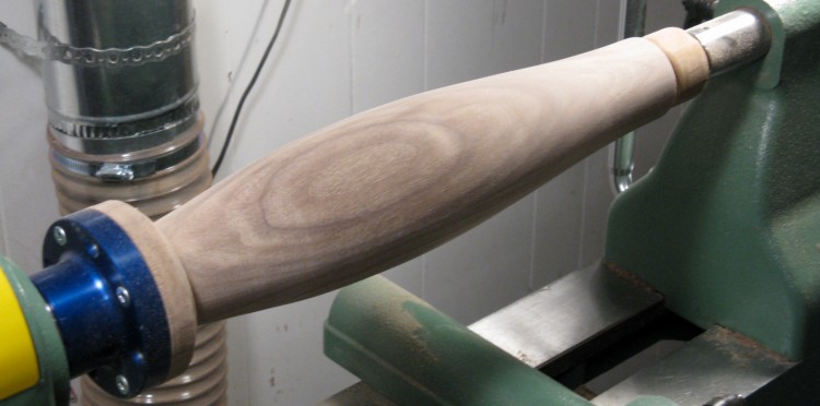
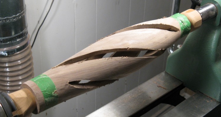
Set up to be supported at both ends
OK - hollowing is done in this shot. The inside has also been sanded to remove the cutting marks, done with sandpaper on a long tool.
The steady rest has been removed and the tailstock moved back into position to provide support for cutting the slots planned for the body.
The steady rest has been removed and the tailstock moved back into position to provide support for cutting the slots planned for the body.
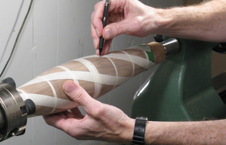
Marking slot edges based on tape outlines
The spiral pattern of the cutouts was established using good ol' masking tape. First the narrow pieces were added and marked evenly around the circumference for accurate positioning, then the pattern pieces were wrapped using the marks as a guide.
This shot shows the pattern being transferred to the wood by tracing the outline of the tape with a pencil.
This shot shows the pattern being transferred to the wood by tracing the outline of the tape with a pencil.
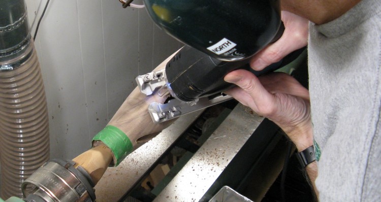
Cutting the slots
I had to ponder the best way to cut the slots in the barrel, since I wanted the edges of the slots to point toward the center of the barrel, which meant the angle changed along the length of the slot.
Ultimately I settled on the jigsaw which worked pretty well, largely since I wasn't trying for high accuracy for the first cut.
Ultimately I settled on the jigsaw which worked pretty well, largely since I wasn't trying for high accuracy for the first cut.
Slots rather roughly cut out
So here the slots have been roughly cut out, but need rather a lot of attention to achieve a consistent width and smooth edges.
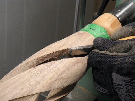

And here are the "lots of attention" shots. In no particular order (since in fact I switched back and forth) the edges were stick-sanded, scraped, drum sanded and rasped. In this process the edges also received a slight rounding.
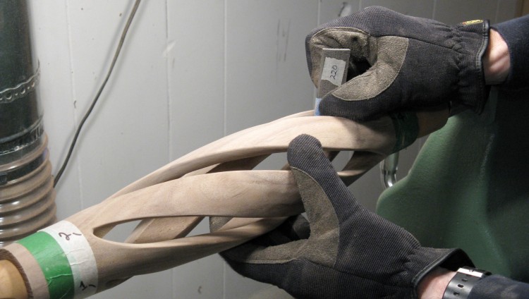
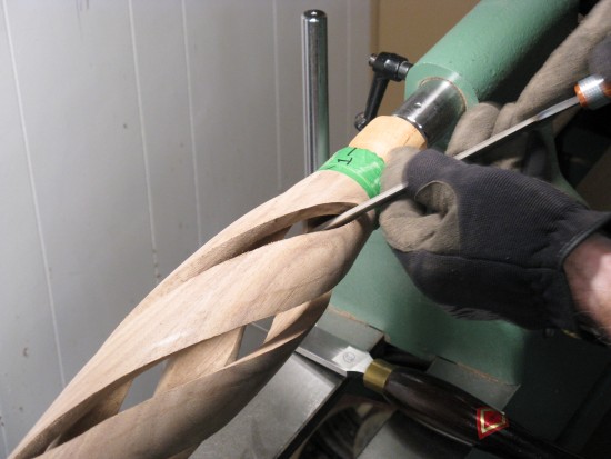
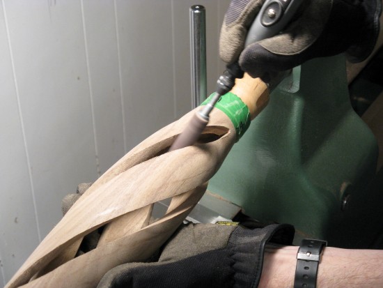
And finally, hand sanding
Finally, the edges were hand-sanded to remove all tool marks and give the final shape.
Mostly done, the body was then set aside to work on...
Mostly done, the body was then set aside to work on...
2. Base
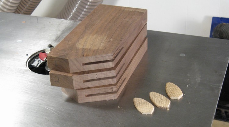
Base pieces with biscuit slots
I decided to make the base from three separate pieces for a more symmetrical look. Here the pieces have been cut out oversized and slots added to accept the biscuit joint reinforcements.
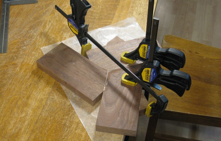
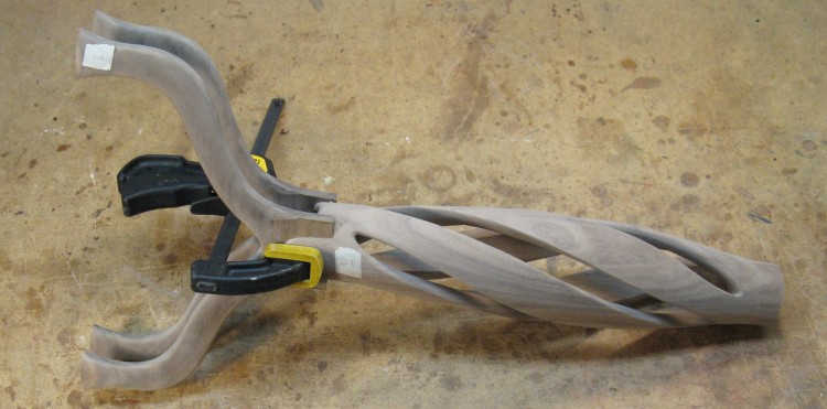
Gluing together the base
I glued on some little wedges to give the clamps a secure spot to squeeze the oddly-shaped assembly - the horizontal clamp is using one. I started by gluing two of the base pieces together, and shown here is the third piece being attached.
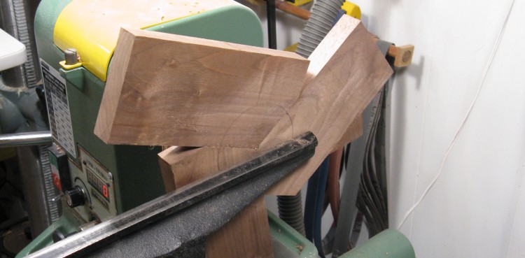
Getting ready to make a base cutout
I belatedly decided that the base might not have enough strength since end-grain glue joints like the ones in the middle are not particularly strong and I wasn't convinced that the biscuits were enough to compensate. The solution was to add a circular "plug" that spanned all three pieces to provide more strength.
I thought the best way to do that was to cut a round hole and fill it with a round plug. Here the base has been mounted on the lathe in preparation for cutting the hole.
I thought the best way to do that was to cut a round hole and fill it with a round plug. Here the base has been mounted on the lathe in preparation for cutting the hole.
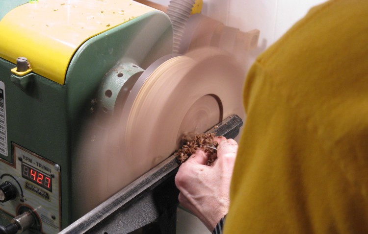
Actually making the base cutout
Here a small scraper is being used to excavate the base cutout.
Ya wanna be sure to keep your knuckles out of that blurry area...
Ya wanna be sure to keep your knuckles out of that blurry area...
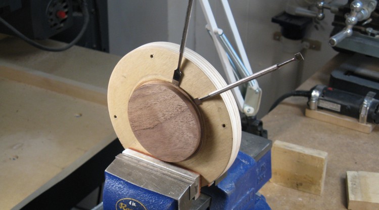
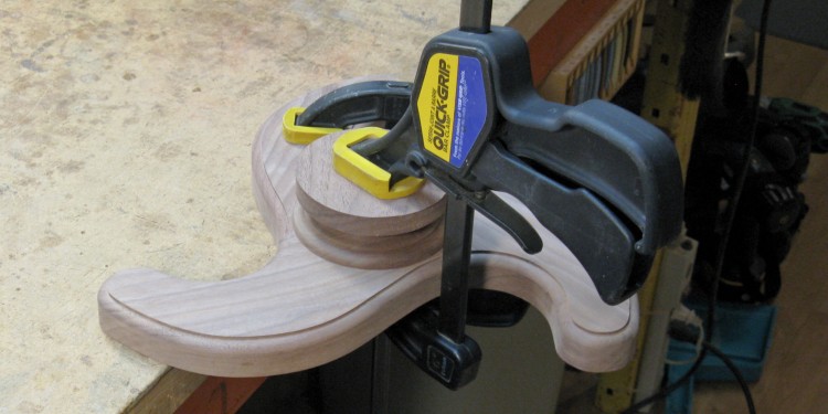
Prying off the base plug
Once the cutout was completed, the base came off the lathe and a thin piece of wood went on, to be cut to the same diameter for a matching plug. In this shot, the plug is complete and is being pried off the piece of plywood it was mounted to.
I used thin double-sided tape like the type that comes with window plastic kits to hold the pieces together. It does a good job, but takes a bit of effort to separate them. I usually use some thin spatulas like the ones shown here to do this.
I used thin double-sided tape like the type that comes with window plastic kits to hold the pieces together. It does a good job, but takes a bit of effort to separate them. I usually use some thin spatulas like the ones shown here to do this.
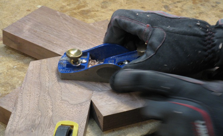
Evening-up the plug in the base
The plug was glued into the bottom of the base and after it dried, I planed off the bit of extra thickness I had left.
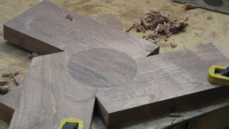
Base reinforced on bottom with plug
And here the base plug is done, now flush with the surface.

Pattern drawn on
I was a bit short on the wood used to make the base, so it was made less oversized that I might otherwise have done. As you can see here, the pattern goes pretty much right to the edge. Every edge.
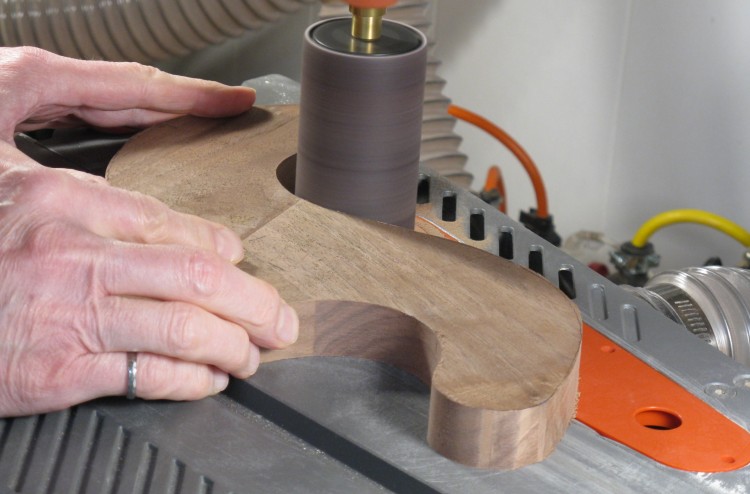
Smoothing the base curves
I cut out the base using a bandsaw, and then it was over to the spindle sander to smooth off the edges and get the shape right down to the lines.
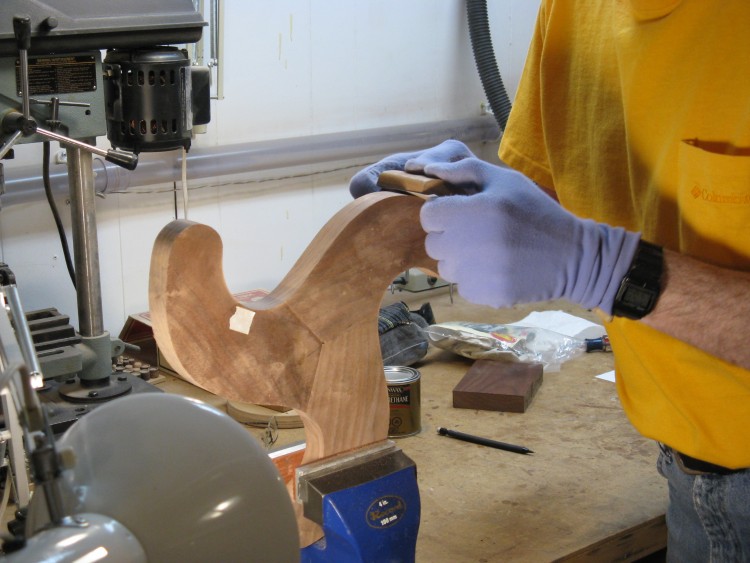
A bit of hand smoothing
It's tough to get curves super-smooth with a spindle sander, so the base needed some hand-sanding after that. Typically I'll use wood blocks to hold the sandpaper and sand any imperfections until a finger run over the curve can no longer detect any wargles.
Well the word "wargle" looked funny so I had to look it up. And apparently wargle isn't a word known to the World Wide Web. Clearly it is out of touch. Anyway, it's sort of like a wiggle or in some cases a warble.
Well the word "wargle" looked funny so I had to look it up. And apparently wargle isn't a word known to the World Wide Web. Clearly it is out of touch. Anyway, it's sort of like a wiggle or in some cases a warble.
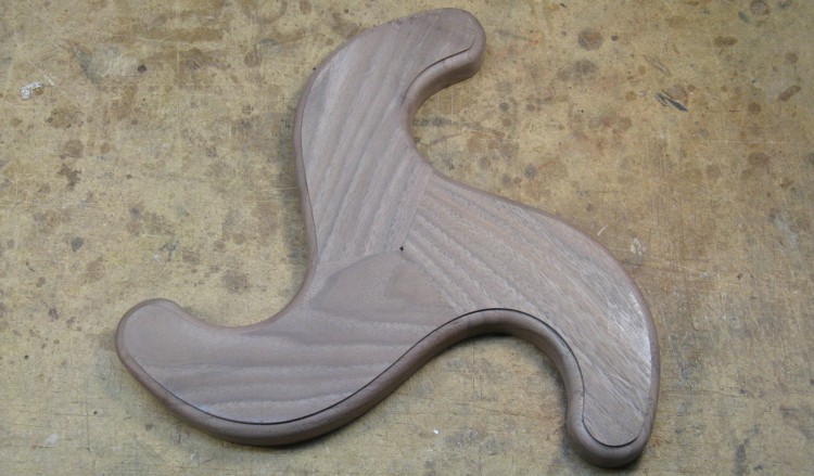
Edges of the base have been contoured
The last step on the base was to contour the edges for a less rectangulary look.
And, no "rectangulary" isn't known to the WWW either, but I don't suppose it needs explaining.
And, no "rectangulary" isn't known to the WWW either, but I don't suppose it needs explaining.
3. Feet
A blank for one of the feet
The feet were pretty straightforward, just being 1"-thick turned pieces. Here a piece of wood cut approximately round has been attached with temporary glue to a scrap dowel and clamped in the adjustable jaws on the lathe.

...and top
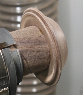
Bottom of the foot
After a bit of turning to form the top profile and a ring-like sub-foot on the bottom, a bit of sanding brought one of the feet to this point.
4. Plinth
Cutting slope on plinth
OK, that foot one was a pretty short section. Here's another;
The plinth sits on the base to support the body. It's a pretty straightforward turning and is shown almost completed in this photo. Here I'm completing the final shape using a tool I made for just this cut.
The plinth sits on the base to support the body. It's a pretty straightforward turning and is shown almost completed in this photo. Here I'm completing the final shape using a tool I made for just this cut.
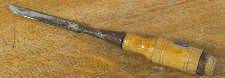
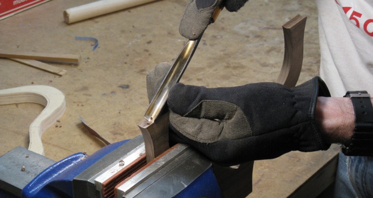
Custom scraper made from tragic-looking chisel
I needed an acute undercut angle for the plinth and didn't see any good way of doing it with standard tools, so I made a custom-shaped scraper out of an old battered chisel, shown here. I used it once and then was done. Tho' in fact I've used it a few times since due to its handy angle so it wasn't as much of a one-shot as I'd expected.
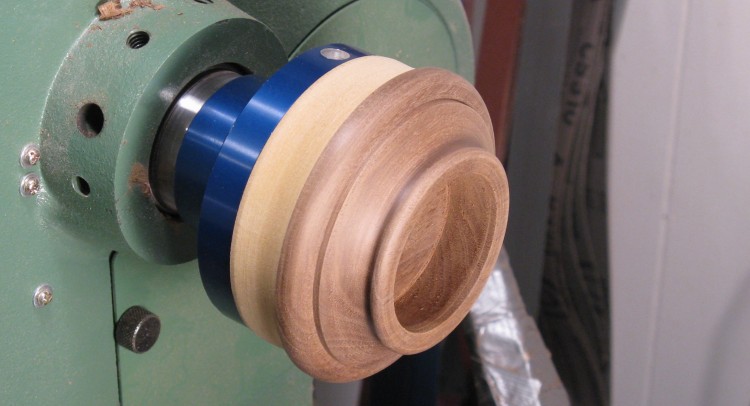
Plinth done
The plinth needs to surround the bottom of the base so it included an appropriately-sized hole in the top. Here it has been sanded and is ready to come off the lathe.
5. Arms
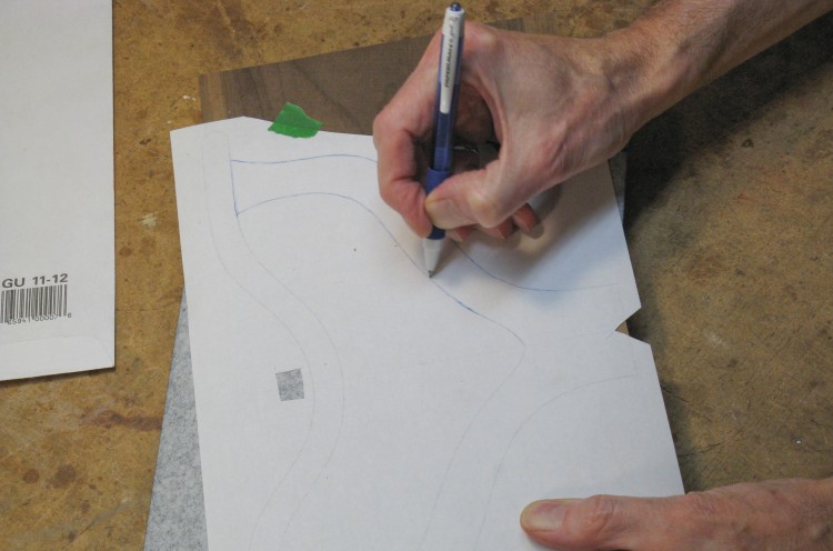
Tracing pattern for arms
So next up: the arms.
My normal technique of trace-the-pattern-onto-the-wood-with-carbon-paper was used, as may be deduced by inspection of this photo.
My normal technique of trace-the-pattern-onto-the-wood-with-carbon-paper was used, as may be deduced by inspection of this photo.
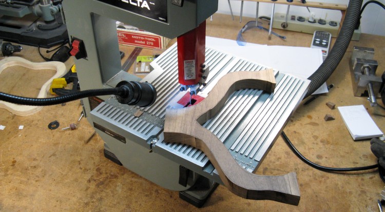
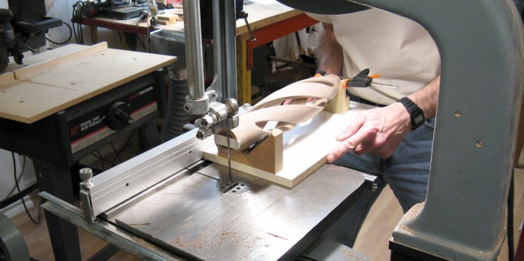
The arms were cut out using a mini-bandsaw
Two layers of wood were taped together so both arms could be made at the same time. Here they've just been cut out on a small bandsaw.
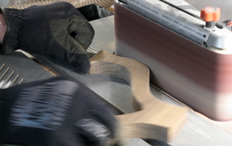
...and then shaped on the horizontal belt sander
Then back to the belt sander to sand down to the marked outlines.
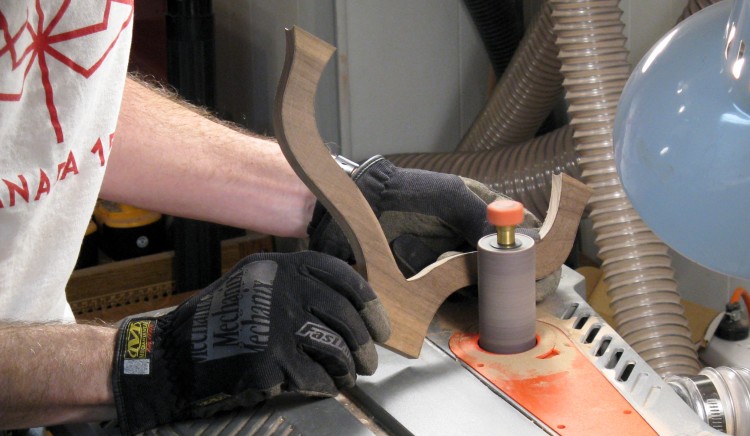
Contouring the arms
The arms needed to be shaped to get the cross-section from rectangular to elliptical (i.e less rectangulary). I used the spindle sander and then a small drum sander to do most of that, and then hand-sanding to get to the final shape.
Contouring the tops
The round(ish) rails rest on top of the arms, so those surfaces were hollowed to match. The ends of the arms weren't perfectly consistent, so I labelled the position and orientation of the arms and modified each of the top surfaces to match the proper rail end.
6. Rails
Getting ready to cut out the rails
The last wooden parts needed were the rails that support the sling. These were made with a dip in the center to make it easy to grab the tablet. Of course, that made it tricker to attach the sling, but then I only had to do that once.
Here one rail has been marked on a properly-thick piece of walnut, and the second is ready to be taped to it so both can be shaped at the same time like was done with the arms.
Here one rail has been marked on a properly-thick piece of walnut, and the second is ready to be taped to it so both can be shaped at the same time like was done with the arms.
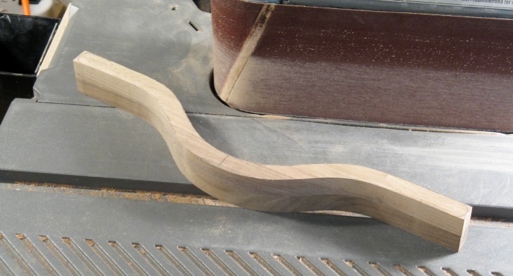
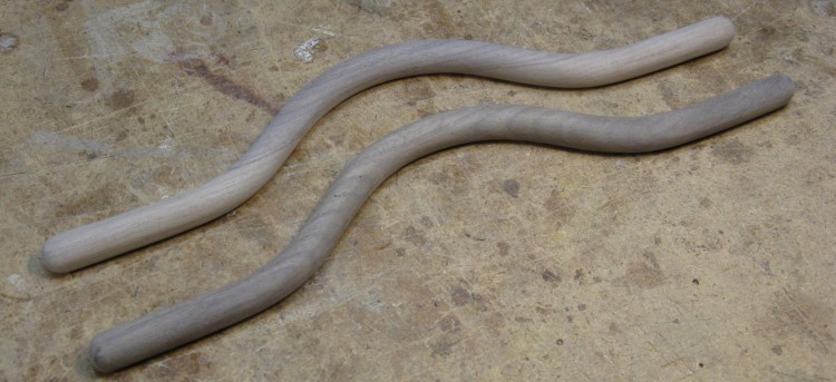
Rails shaped
And again with the bandsaw/belt sander combination for cutout and shaping, so here the rails are ready to be pulled apart and go on to the next stage.
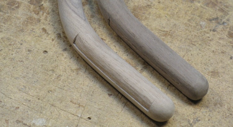
The first step in rounding the rails
...which was rounding. The spokeshave was used to remove the four corners and then the resultant 8 corners.
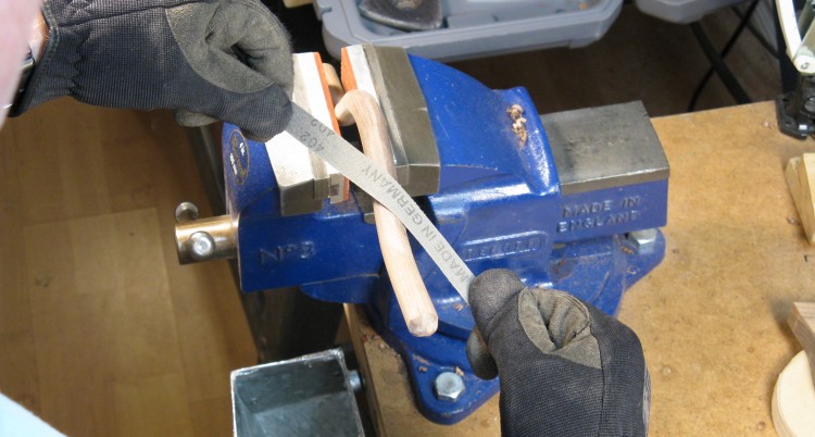
Sanding to complete rounding
The rounding of the now 16-sided rails was completed by sanding.
Rails modified to accept sling tabs
The final step was to add some shallow cutouts in three places along each rail to accept tabs of the sling material. A single layer of the material will wrap over the rail and be glued into each of these cutouts. The depth is appropriate to have the material flush with the wood.
Rails done (although kind of upside-down in this shot)
The completed rails.
7. Assembly

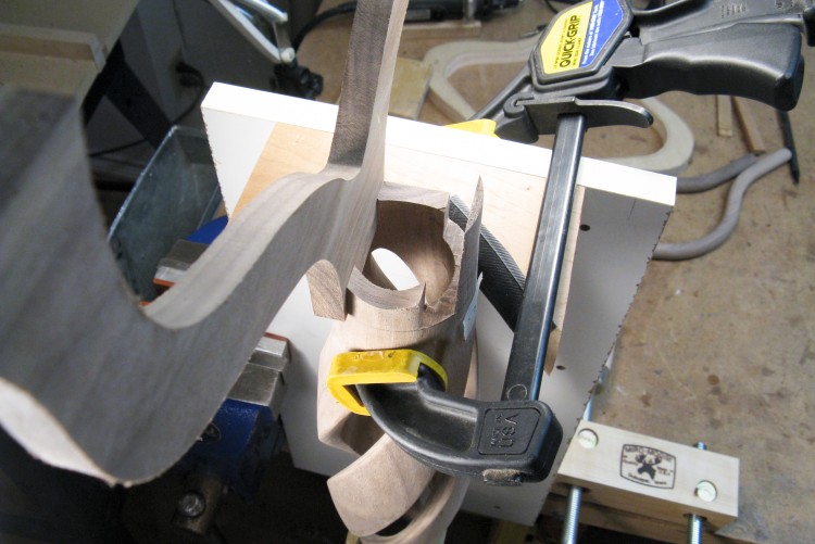
Body-support jig
The shape of the body made it tough to hold in a stable manner, so I made a little jig with notches in which it would rest.
Cutting arm slots in the body
The jig was made to hold the body horizontal and parallel to the bandsaw fence. In this photo, the top of the body will be cut to accept the arms.
Test-fit of one of the arms
This weird viewing angle shows a test-fit of one of the arms to the body. I did some minor work on the body to get a good fit of both of the arms.
Body top shaped and getting sanded
The top of the body was straight and flat, so I did a bit of shaping to make it look a bit more finished.
Gluing in the arms
The arms were glued into the body as shown here.
The arms had been left unshaped on their bottom ends since they needed to be blended into the body after assembly. And as bizzarre as it may seem, I don't actually have a photo of that process(!) But despite the lack it did actually happen, and mostly involved a drum sander and of course the inevitable hand-sanding.
The arms had been left unshaped on their bottom ends since they needed to be blended into the body after assembly. And as bizzarre as it may seem, I don't actually have a photo of that process(!) But despite the lack it did actually happen, and mostly involved a drum sander and of course the inevitable hand-sanding.
Gluing the plinth onto the base
The plinth was centered by eye and glued onto the base.
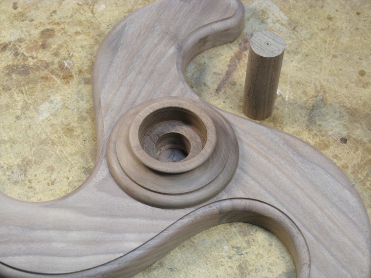
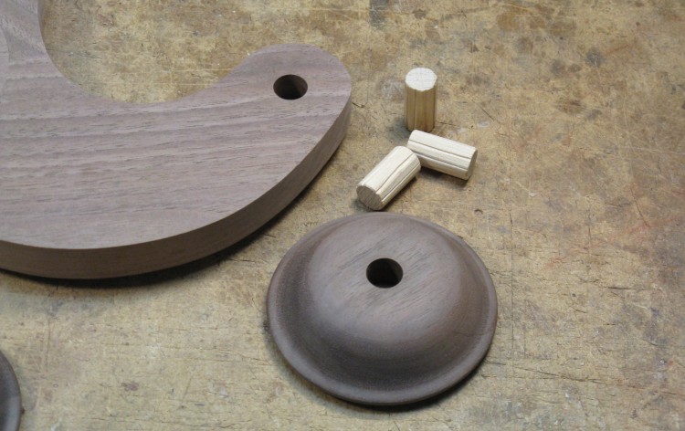
Hole and dowel for body reinforcement
I was a bit concerned about the strength of the base-to-body joint, so I included the supporting dowel shown here. The plinth and base had a 1"-diameter hole drilled most of they way through the base, while the body had been made with a matching 1" hole in the bottom as well.
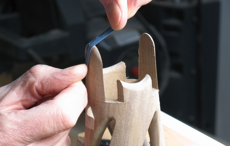
The top of the dowel would be visible through the slots in the body, so (after this photo) it was cut exactly to length and contoured on the top a bit to look a bit less dowely.
The top of the dowel would be visible through the slots in the body, so (after this photo) it was cut exactly to length and contoured on the top a bit to look a bit less dowely.
Holes and dowel for foot reinforcement
I was less concerned about foot-joint strength, but I included a hole-dowel setup for those as well. At the very least, it made glue-up easier as the dowels located the feet and prevented movement when clamped.
When using a dowel in a closed hole, the glue usually forms a good seal between the wood surfaces and prevents air from escaping, resulting in the dowel being pushed back out of the hole. Of course clamping would hold it in place, but assembly is easier if this doesn't happen. To prevent this problem, the dowels get slots in the side to allow glue or air to escape.
When using a dowel in a closed hole, the glue usually forms a good seal between the wood surfaces and prevents air from escaping, resulting in the dowel being pushed back out of the hole. Of course clamping would hold it in place, but assembly is easier if this doesn't happen. To prevent this problem, the dowels get slots in the side to allow glue or air to escape.
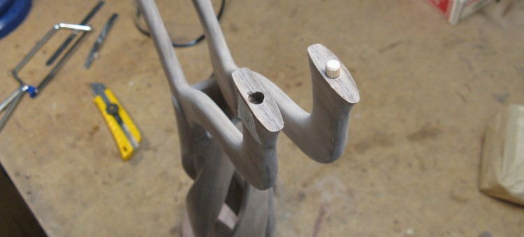
Arms with holes and dowel for reinforcement
The small gluing surfaces for the arm-to-rail joints needed reinforcement, so they received the dowel-and-hole treatmant as well.
I used a commercial 1/4" joint dowels here and the slots (or flutes) can be seen on the side.
I used a commercial 1/4" joint dowels here and the slots (or flutes) can be seen on the side.
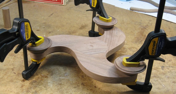
Gluing on the feet
Gluing on the feet was about as simple as glue-ups go. Here they are clamped until the glue sets.
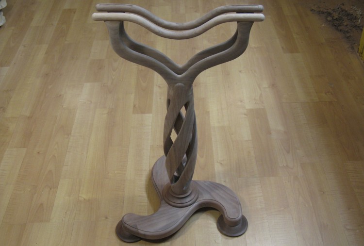
Except for the sling, the holder is fully assembled
And "off-stage" the body was glued to the base/plinth assembly, and the rails to the arms, with this shot showing the completed assembly of all the parts but the sling.
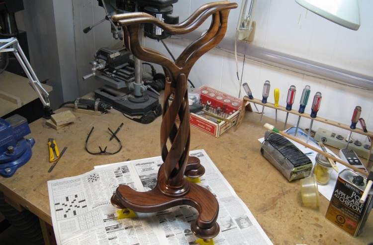
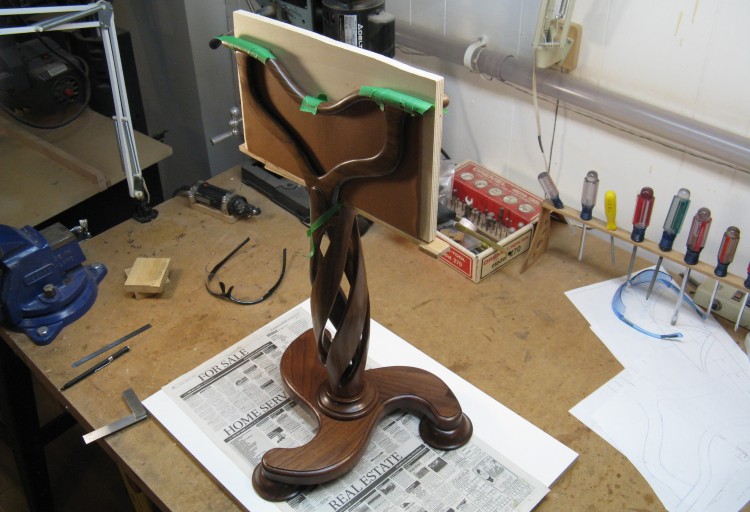
First coat of varnish
The plan was to glue the sling to the rails, so the finish needed to go on first. Here is the traditional first-coat-of-finish shot.
I actually used my normal Wipe-On Poly for the first coat before remembering that I had a new finish to try - a similar wipe-on varnish by the same company called Fast-Drying polyeurethane. I used that for the last two coats.
I actually used my normal Wipe-On Poly for the first coat before remembering that I had a new finish to try - a similar wipe-on varnish by the same company called Fast-Drying polyeurethane. I used that for the last two coats.
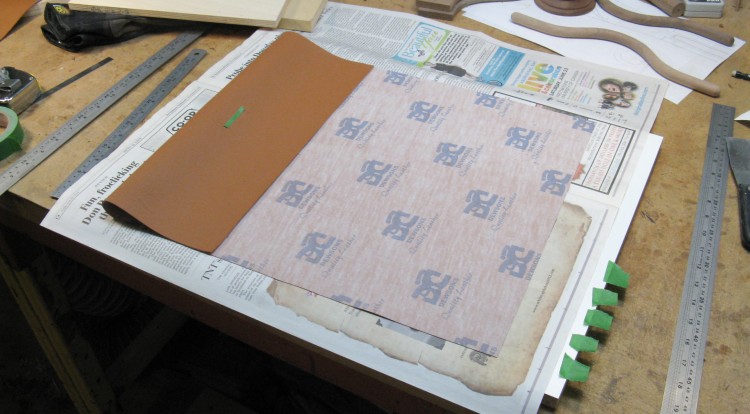
Material for the sling cut to size
The final bit was the sling. I had originally envisioned leather, but was unable to find anything thin enough to work properly in the two layers I would need to acheive two finished sides. I ended up getting a leather-like material that was only about 1/40" thick. Seams and sewing were not going to work so I instead folded the material and glued it to itself with silicone so the ends of the sling were folded and looked finished.
Here the cut-to-size piece is getting ready to be glued.
Here the cut-to-size piece is getting ready to be glued.
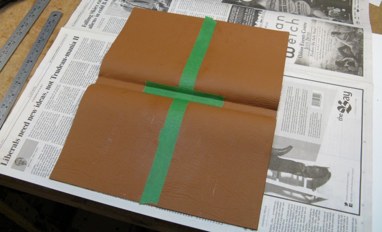
Sling folded, formed and glued
To make the double-sided piece, the seam was taped and the material was folded around an appropriately-sized form to make sure the shape was held after the glue dried. This is the post-gluing piece.
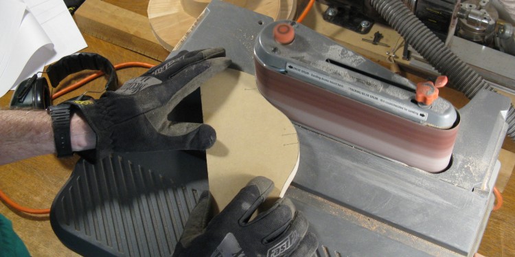
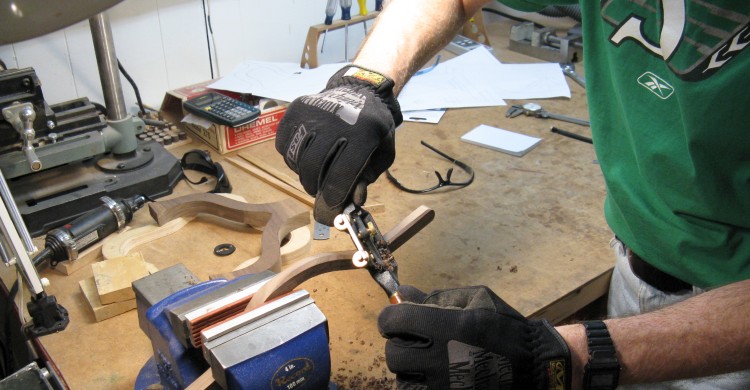
Making a sling cutting guide
The sling needed to be cut to match the curved profile of the rails which didn't seem like it would be too successful if done freehand. For more consistency, I made an appropriately-curved cutting jig which is being sanded to shape in this photo.
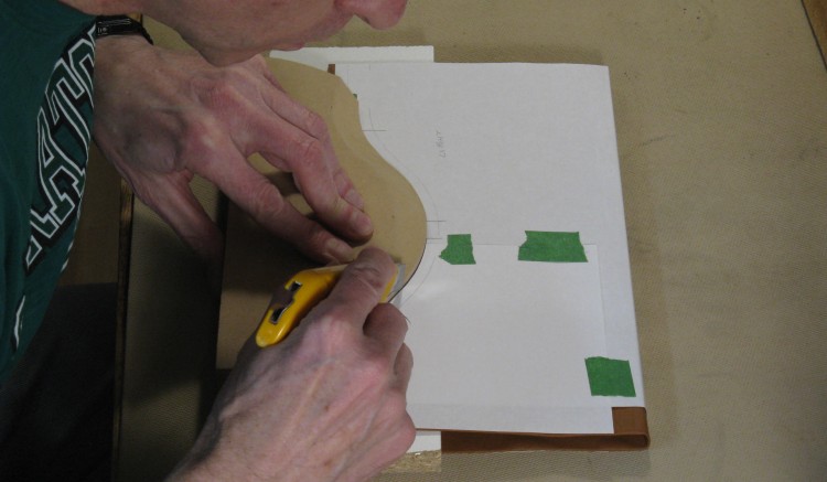
Cutting the sling to align with the curved rails
Then using the jig, the tops of the sling were cut, except for the three tabs sticking up that would be used to glue it to the rails.
Sling glued on to varnished stand
I used a latex fabric cement to glue the tabs of the sling to the rails, hidden here under green tape holding them flat while the glue dries.
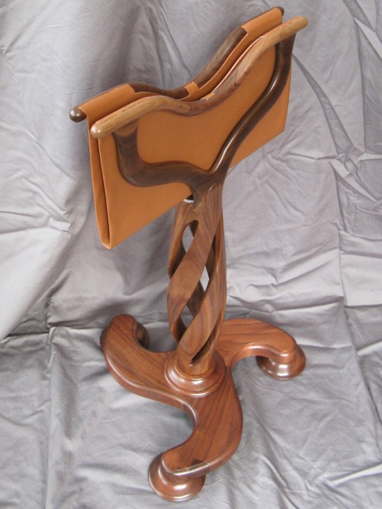
Done
And that was it. The completed stand on the traditional photographer's backdrop (OK, wrinkly bedsheet) is here.


