
Warning! Long post - no exit. Next gas: 70 photos.
Details
The inspiration
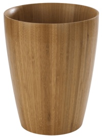
I usually gather images of an item I intend to make. These often have an interesting pattern/shape/finish and are used as design inspiration but sometimes they are just something I'd be happy replicating. In this case I had a few dozen examples and refreshed that with a few more but an older image of a tapered wastebasket looked the best to my eyes.
In addition to the shape, I liked what looked like fine vertical laminations. An image search revealed that this was a Bamboo wastebasket so the laminations were sort of part of the manufacturing process, and something that is necessary to make any larger Bamboo woodwork. The Walnut color isn't usually a feature of Bamboo but I hear stains are a thing.
I decided to replicate the design in shape, color and construction although I would use Cherry rather than Bamboo. The original seemed to have upwards of 100 layers around the circumference but I didn't think the look would suffer much from a more modest number and aimed for 72. And, er...missed; it ended up with 80.
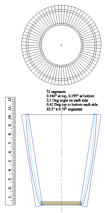
The plan, with numbers
Stave Cutting
The first thing I needed to find out was whether I could even cut the staves well enough with the equipment I had. They needed to be tapered in two dimensions with shallow angles and have straight and flat-enough surfaces to be able to laminate them together cleanly. The only good choice was the radial arm saw so I started setting that up to check out what it could do.
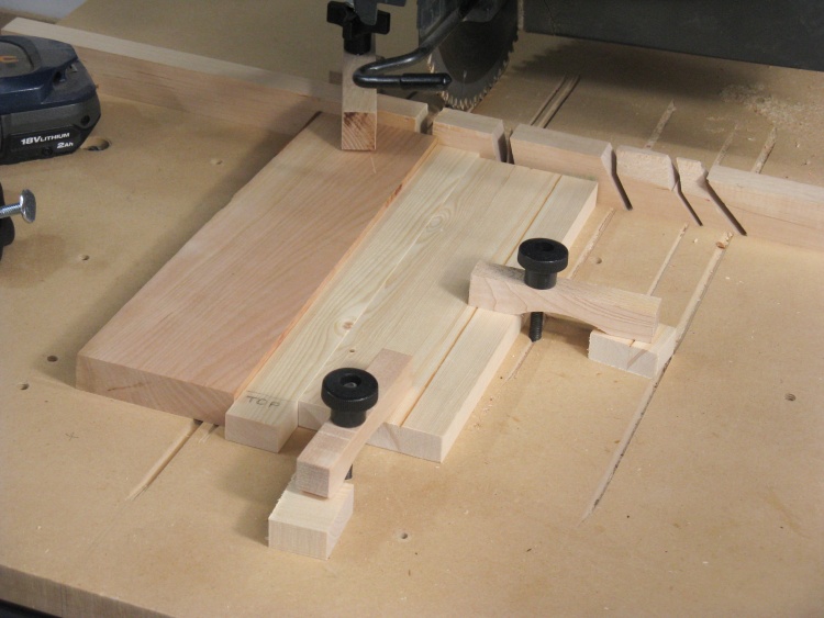
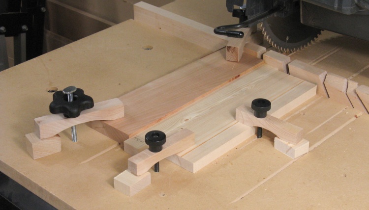
Stave-cutting test setup
At the time of this photo, I'm fairly far along in the process. I've cut 5 or 6 test staves and the quality and size look like they should be acceptable. For consistent cuts I've added a stop with a removable section and clamped it the appropriate distance and angle to get the end-to-end taper I need.
On the left is a piece of Cherry I'm using for the test staves.
On the left is a piece of Cherry I'm using for the test staves.
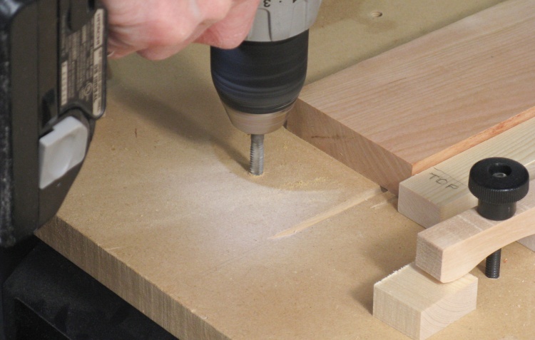
Tapping the table for another clamp
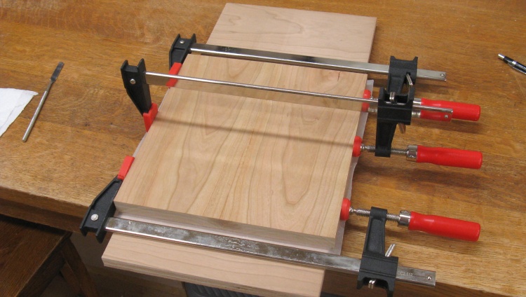
I wanted to use as much as possible of each Cherry piece while losing as few fingers as possible so I decided the Cherry would need to be clamped in place so it didn't have to be hand-held.
I had already added a clamp reaching over the short fence at the back and here I'm adding another for the front of the board.
Like the one on the right side of the photo, these are simple hold-downs consisting of a screw threaded into the saw table along with a wooden toggle that gets tightened down with a threaded knob.
Wood clamped in place
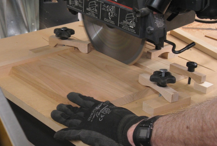
This shot shows the complete setup. The spacer to the right of the Cherry piece is set in place while the Cherry is snuggled up to it and the clamps are tightened, then the spacer is removed before the cut is made. This allows the cut piece to fall away from the blade on the return stroke to prevent marring.

Stave cut free
...like that.
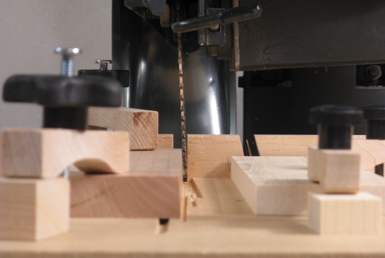
The 2.5° angle on the stave sides
The blade is set to a shallow angle to cut the radial sides of each stave. Once a stave is cut off, the Cherry piece is flipped end-for-end so the next piece is correctly angled.

This shows a slightly-speeded-up sequence of cutting a couple staves. There were over 70 to do so I had plenty of opportunity for videos...
Wastebasket Body Construction
Once I proved to my satisfaction that I could accurately cut the staves, I was ready to do it for real. And then eventually stick them all together.
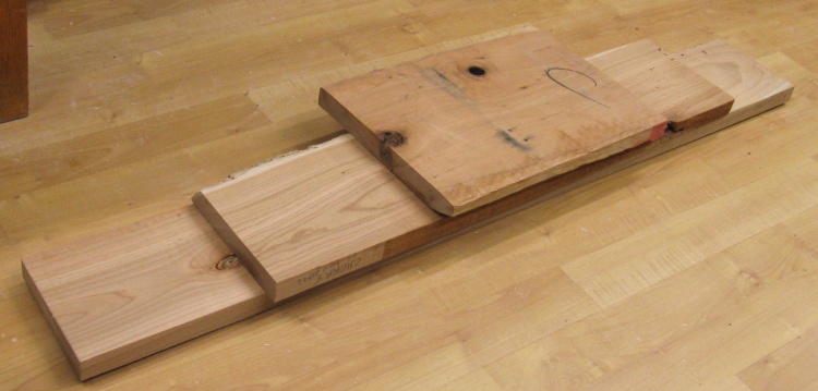
The surprisingly large pile of cherry I'll need
My calculations suggested that I'd need a width of about 27" of cherry at 11" long. This pile (after subtracting ugly edges and the odd knot) should be just about enough.
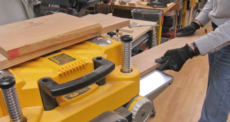
Planing to a consistent thickness
I started by planing all the boards to around 0.8" thick.
Widening the cherry for fewer end bits
To avoid handling too many thin pieces as the cuts narrowed the boards, I glued some 11"-long sections together side-to-side so I could work with fewer but wider boards. Fortunately I had enough wood that I didn't need to use any of the staves that had the glued joint in them.
Slicing a stave of the widened board
And then I started cutting staves.
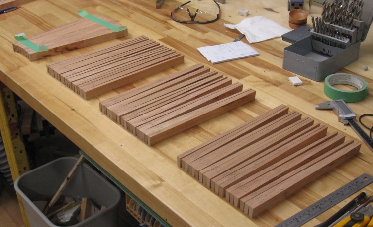
72 staves and a few spares
It didn't take too long until I had enough for the whole body, plus a few spares just in case.
Mind you, I did need to stop and empty the duct collector since more than a quarter of the wood was turned into sawdust.
Mind you, I did need to stop and empty the duct collector since more than a quarter of the wood was turned into sawdust.
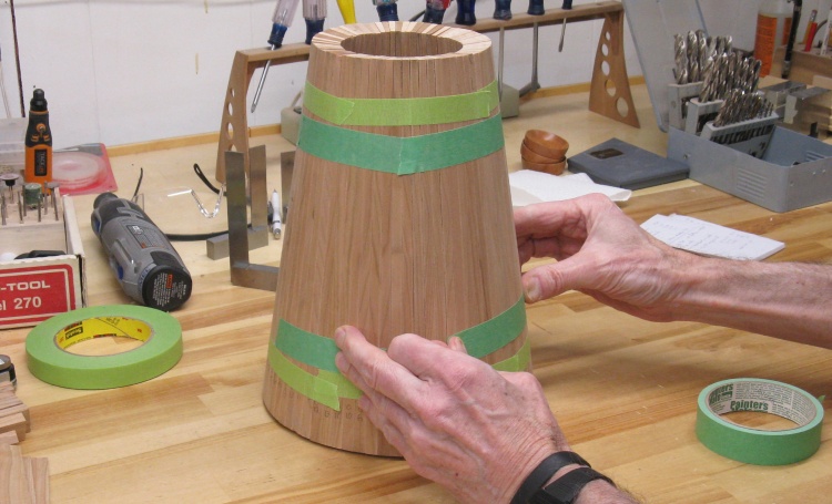
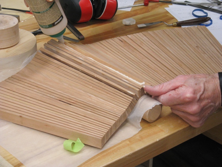
The first tape-up
I used masking tape and later a more-sticky binding tape (the lighter-green stuff) to hold together four groups of 18 staves. Then those four were assembled into a full circle.
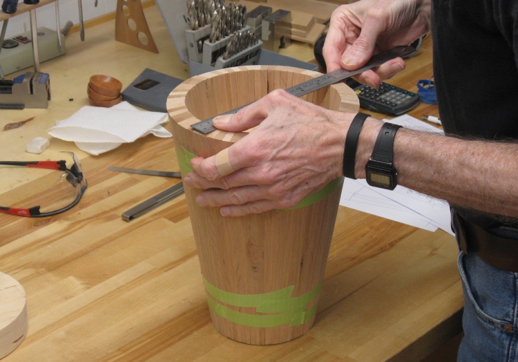
Umm...looks kinda small?
The diameter looked kind of small and the ruler agreed. I'm not sure what exactly happened since the staves seemed to be the correct size but ultimately both top and bottom diameters were about 0.6" smaller than I was aiming for.
It doesn't sound like much but the proportions definitely looked off (not helped by the fact that there I'd left an extra inch of height as well).
It doesn't sound like much but the proportions definitely looked off (not helped by the fact that there I'd left an extra inch of height as well).
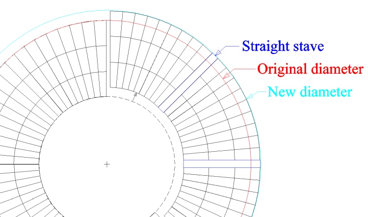
Cheating a bit to increase diameter
After some fiddling with the drawing I decided the best solution was to just insert some extra staves periodically to move the diameter out to what I wanted. Using non-tapered staves would increase both top and bottom diameters by the same amount which was exactly what was needed. As a bonus, the straight-sided staves should be pretty easy to make.
That ends up putting some "ripple" in the surfaces but they will be smoothed on the lathe anyway so that was a non-issue.
That ends up putting some "ripple" in the surfaces but they will be smoothed on the lathe anyway so that was a non-issue.
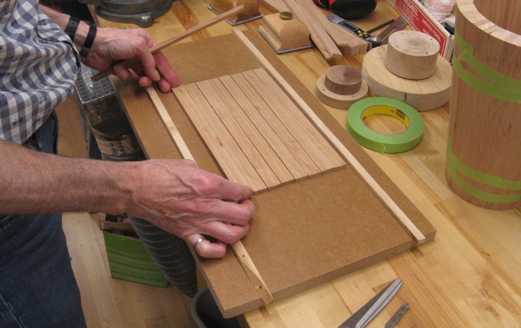
Setting up to plane some rectangular staves
I reconfigured the radial arm saw back to normal which meant it cut vertically and square and then cut the 8 straight staves needed plus a spare. I cut them a bit oversized and then planed them down to the desired thickness.
In this photo I'm adding the staves to the planer sled.
In this photo I'm adding the staves to the planer sled.
Inserting the new staves
They went in every 9th stave.
Holding the glued-up pieces
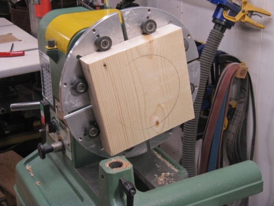
A base chuck blank ready to turn
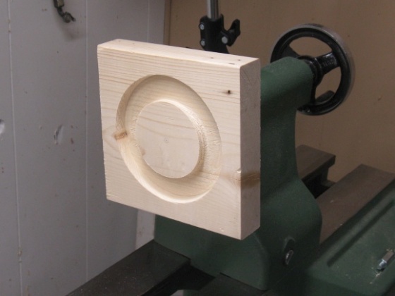
Base chuck turned and mounted on tailstock
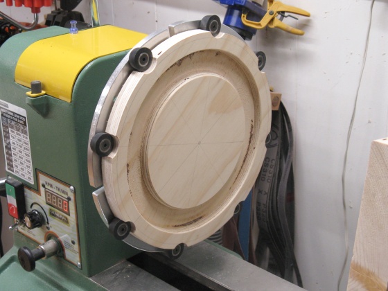
Working on the top chuck
Held in my very hugest chuck
I needed some way to ensure the staves were radially symmetric while drying so the whole thing didn't acquire a lean to one side. The best way I could see to do that was to clamp them into the lathe using top and bottom "chucks" that were properly aligned.
The base would be held at the tailstock end so I needed a smaller-diameter ring that could press-fit over the live center. I just used a piece of construction 4x6 with a hole for the live center in one face and the circular slot for the staves in the other.
A base chuck blank ready to turn
Base chuck turned and mounted on tailstock
The top end was wider so I used my largest jaws set to the widest reach to hold it. I wanted a bit more wood outside the slot for the top so I made it a bit oversized and added indentations for the rubber clamping buttons.
Working on the top chuck
Held in my very hugest chuck
Then I was ready to start the stave gluing;
Starting to glue the first batch of staves
The wastebasket body was opened up by strategically removing tape and then I started somewhere in the middle with the gluing.
I glued the body in groups of 10 or so staves then let those dry before gluing more.
I glued the body in groups of 10 or so staves then let those dry before gluing more.
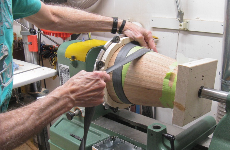
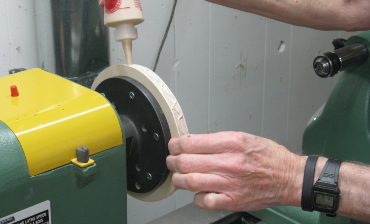
Adding rubber strap for radial pressure
The glued and re-taped body went onto the lathe between the chucks and I stretched a rubber strap (half of an old bike tire inner tube) around to apply radial pressure to the glued joints.
I had actually bought a length of rubber surgical tubing for this purpose thinking it would be just the thing. Unfortunately it stubbornly rolled down the slope no matter how tight I wrapped it. It even did that after I cut it open in a futile effort to get it to lie flat. The inner tube had no such problem.
I had actually bought a length of rubber surgical tubing for this purpose thinking it would be just the thing. Unfortunately it stubbornly rolled down the slope no matter how tight I wrapped it. It even did that after I cut it open in a futile effort to get it to lie flat. The inner tube had no such problem.
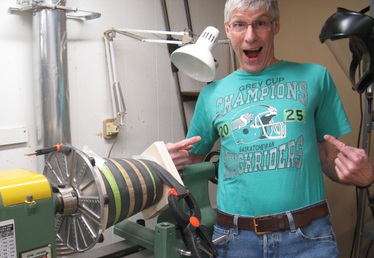
2025 Grey Cup Champions!
The rubber strap was clamped at the end to hold the tension while the glue dried. This photo was taken after the 112th Grey Cup, which you may have heard, the Riders won.
It was a bit early for 2025 Grey Cup merchandise so I modified my 1989 shirt as a stand-in.
It was a bit early for 2025 Grey Cup merchandise so I modified my 1989 shirt as a stand-in.
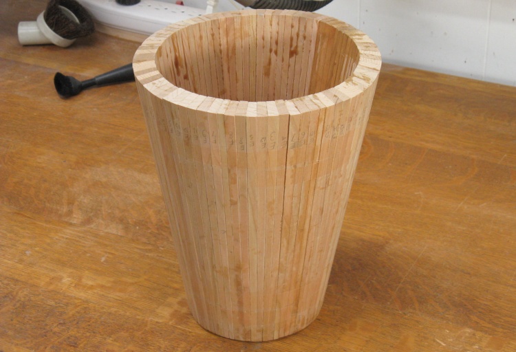
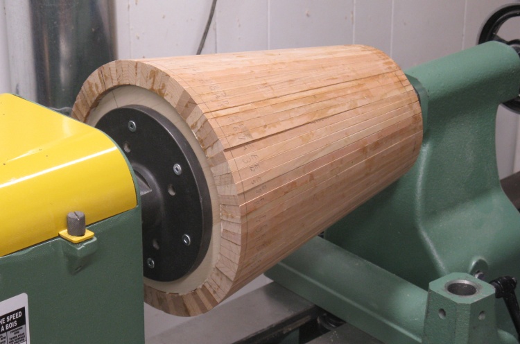
360° glued
After a couple days of gluing it was able to stand on its own without the assistance of green tape.
Turning
The wastebasket at this point was just an empty tube but it needs a bottom and a bunch of smoothing out and shaping on all surfaces and ends. The plan called for the bottom to be inset so I needed a way to hold the top so the bottom could be accessed. I also wanted to ensure that it was turned radially again so I needed to be careful with the centering at both ends.
The approach I took was to add a temporary "cover" at the top that could be attached to a faceplate for turning. But I also wanted the bottom stable and securely centered so I ended up adding a temporary floor as well, an inch or so above where the actual bottom would sit.
The approach I took was to add a temporary "cover" at the top that could be attached to a faceplate for turning. But I also wanted the bottom stable and securely centered so I ended up adding a temporary floor as well, an inch or so above where the actual bottom would sit.
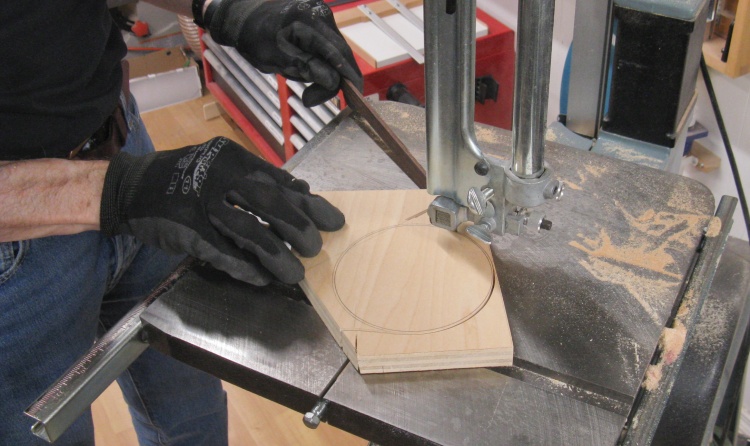
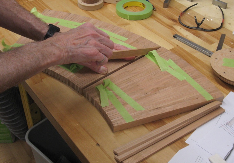
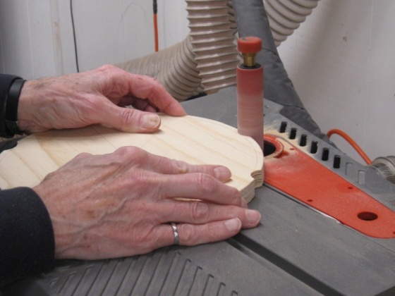
Cutting out a temporary floor
The temporary floor started out as a plywood disc. After cutting, it was rounded and the edges tapered on the belt and disc sanders to nicely wedge into the interior.
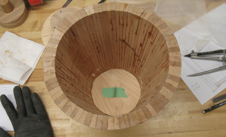
Floor in place
Like that.
It was glued into place and will be cut out once its work is done.
It was glued into place and will be cut out once its work is done.
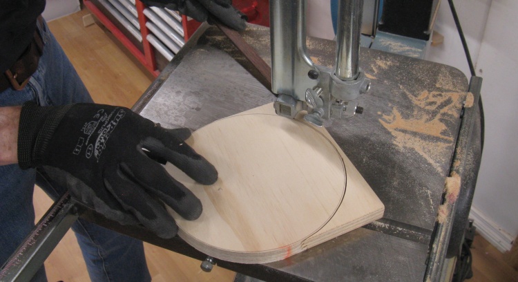
Cutting out a temporary cover
I also needed a piece to act as a cover, so a larger disc was cut out and sanded in the same manner.
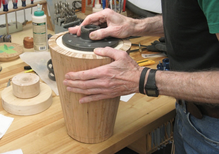
Checking cover fit
The cover is equipped with a faceplate to allow turning of the wastebasket for the first phase of the lathe work.
The glued body wasn't quite round so I used the sander to modify the cover to roughly match the interior for better wood-to-wood contact. In this shot I'm checking the fit before doing more sanding.
The glued body wasn't quite round so I used the sander to modify the cover to roughly match the interior for better wood-to-wood contact. In this shot I'm checking the fit before doing more sanding.
Gluing up cover
I needed the cover to go into the body at just the right angle so the gluing was done on the lathe. I started by applying a generous amount of glue to the cover edge.
Body glued to cover
Then with the tailstock centered and pushing on the temporary floor, the body was mated to the cover.
Bottom centered with tailstock
This shows the tailstock pushing on the temporary bottom. Just ignore the fact that the body is spinning in this shot...
Bottom
The wastebasket body is hollow so it was going to need a proper bottom. There were a few considerations:
1. The bottom should be inset into the walls for an integrated fit;
2. I didn't want seasonal expansion/contraction of the bottom to force the body apart;
3. There ultimately needs to be a circular foot integrated into the bottom, and
4. I need to turn the body from the bottom without wrecking the bottom.
Eventually after abandoning any simple approaches, I came up with one of my custom way-too-many-steps plans;
1. Use the inset temporary floor and cover faceplate to allow access to the bottom to turn an appropriate inset
2. Use plywood (made from Cherry) for the floor so seasonal expansion is minimized
3. Add a thicker layer to the bottom that will eventually be removed except for the foot portion, and
4. Glue a disc to the foot layer to hold a faceplate for turning. It will all be removed with most of the foot layer at the end.
5. Whew!

Cutting plys for the base
Step 1 was already in place so the next thing was to make a plywood floor.
I rather arbitrarily decided on a 5 layer plywood with about 1/16"-thick plys, all of which I managed to get out of this one piece of Cherry. They were cut extra-thick and would be further smoothed and thicknessed on the drum sander.
I rather arbitrarily decided on a 5 layer plywood with about 1/16"-thick plys, all of which I managed to get out of this one piece of Cherry. They were cut extra-thick and would be further smoothed and thicknessed on the drum sander.

Thinning to about 1/16"
The 5 plys (plus a spare) were run through the drum sander numerous times to get both sides flat and smooth, ending up at around 0.063" thick.

Mixing up 7ml of epoxy
Lamination time!
I used a slow-set epoxy to give me enough time to spread it on four surfaces and set up the clamping. I aimed for 0.004"-thick epoxy layers which worked out to about 7 ml of epoxy required and here I'm pouring the hardener into the resin before giving it a good stir.
I used a slow-set epoxy to give me enough time to spread it on four surfaces and set up the clamping. I aimed for 0.004"-thick epoxy layers which worked out to about 7 ml of epoxy required and here I'm pouring the hardener into the resin before giving it a good stir.
Spreading epoxy on second layer
The epoxy was spread evenly between each layer with a small notched spreader that I whipped up for previous work.
Each cherry ply is laid with the grain at right angles to the one before, which is what gives the plywood strength in all directions and the reluctance to expand with humidity changes.
Each cherry ply is laid with the grain at right angles to the one before, which is what gives the plywood strength in all directions and the reluctance to expand with humidity changes.
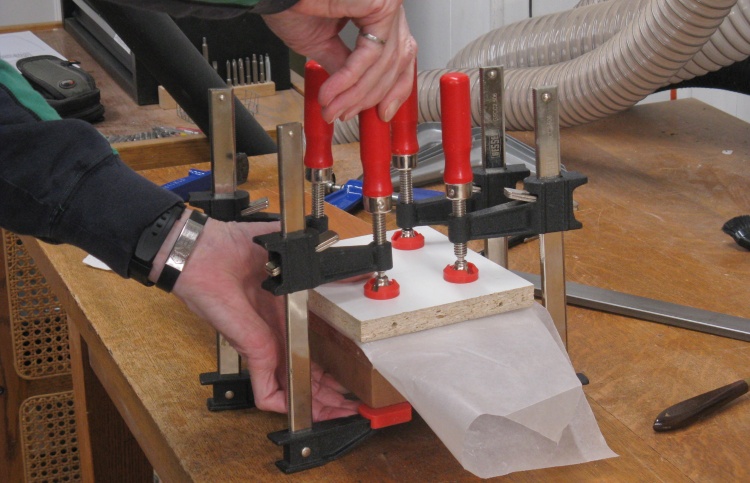
Clamping epoxied base
The stack of 5 glued plys was clamped - firmly - between flat surfaces until the epoxy set.
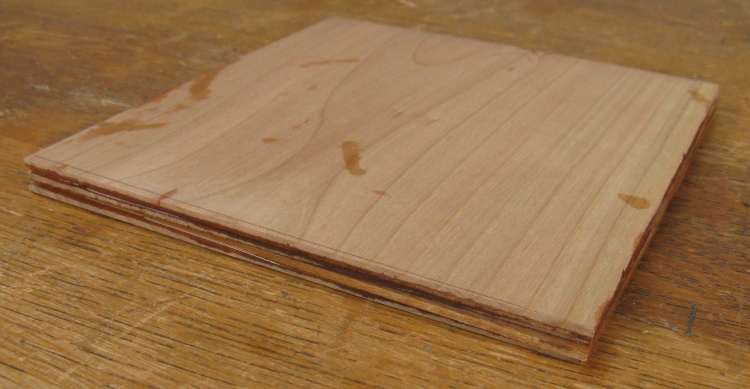
The 5 layer base blank
This shot shows the resulting plywood which is about 5/16" thick, complete with some epoxy smears on the surface due to fumbling during the clamping operation. A bit of sanding will get rid of those.
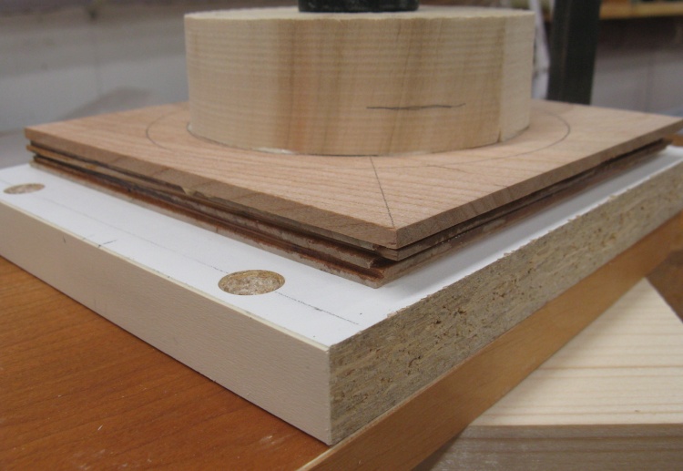
Adding a foot layer and faceplate cylinder
Steps 3 and 4 above describe adding a thicker layer to the bottom to provide material for a turned foot plus adding a disc for mounting a faceplate.
Both of those are shown in this photo; they have been glued on to the 5-ply bottom piece and a barely-in-the-shot clamp is holding things together until the glue sets.
Both of those are shown in this photo; they have been glued on to the 5-ply bottom piece and a barely-in-the-shot clamp is holding things together until the glue sets.
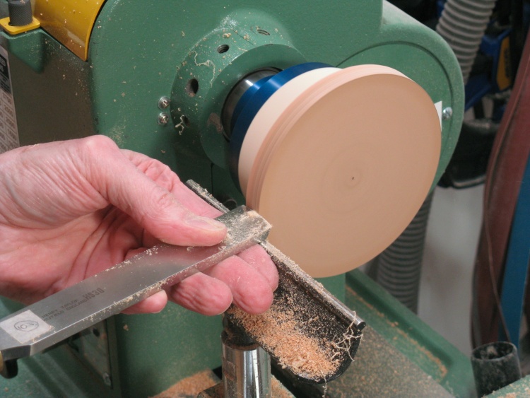
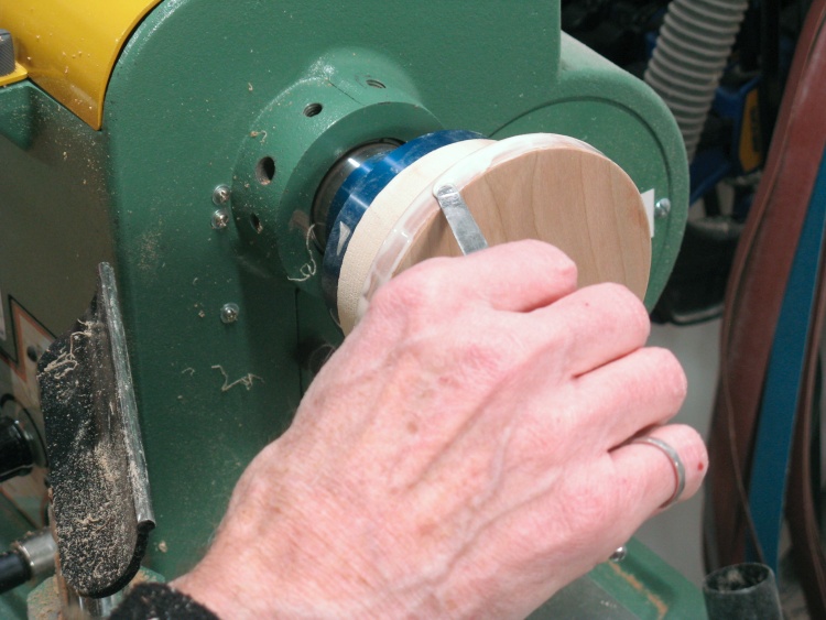
Rounding the base
Upon drying of the wood glue, a faceplate was added and the base was cut roundish on the band saw and then made perfectly round through the good offices of this large scraper in combination with the magic of circular symmetry.
Cutting a notch for the base
The wastebasket body then was moved to the lathe and attached using the large faceplate on the glued-in cover. The first step was to shorten the bottom end of the staves by half an inch or so to hit the target 10" height.
Then it was a matter of cutting a slot at the base that matched the diameter of the bottom.
Then it was a matter of cutting a slot at the base that matched the diameter of the bottom.
Gluing 'er up
Once a close fit was achieved, the bottom went back on the lathe and its edges received a generous coating of glue.
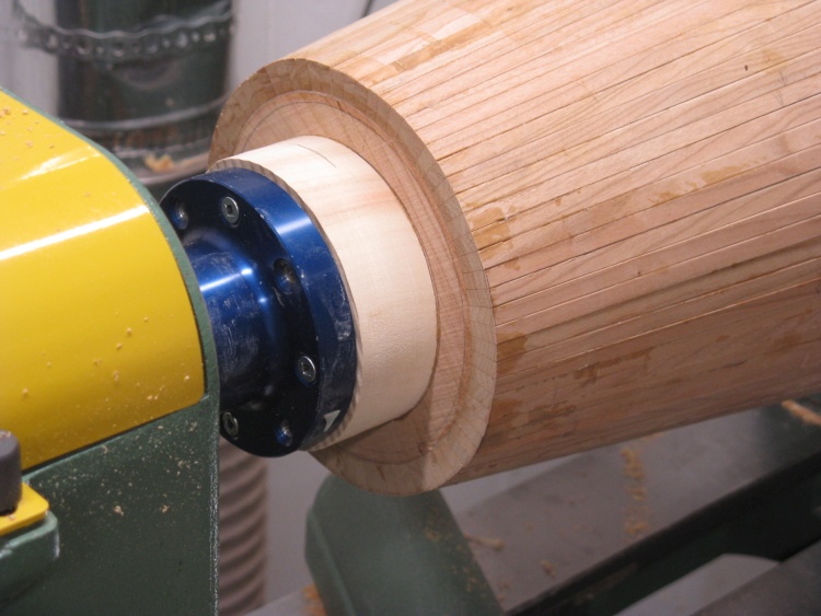
Base glued in
...and then the body was mated with the bottom, the other end being centered to ensure "squareness".
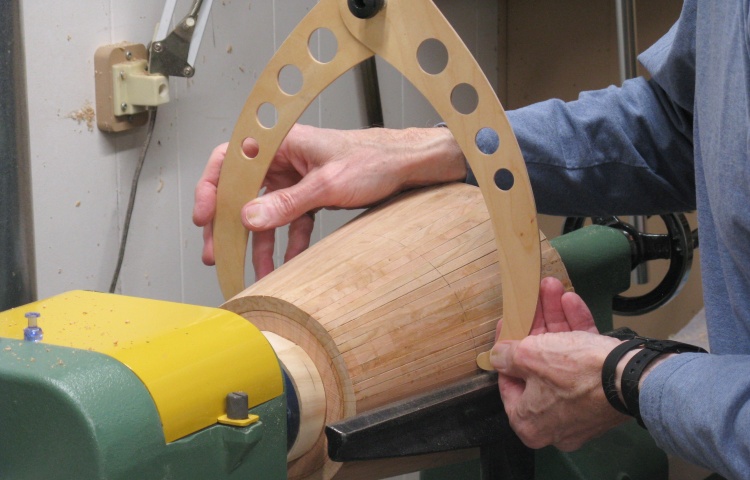
Breaking out the big calipers
We have now arrived at stage Whew! where the wastebasket is finally ready for some shaping.
To measure diameters of this largish piece, I broke out the Big Calipers.
To measure diameters of this largish piece, I broke out the Big Calipers.
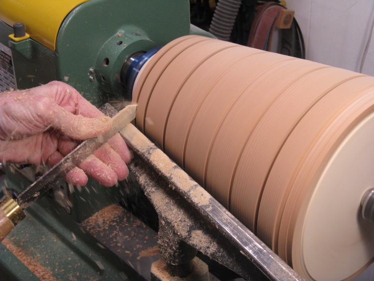
Cutting guide slots
I used my standard technique of cutting periodic slots to the target diameters.
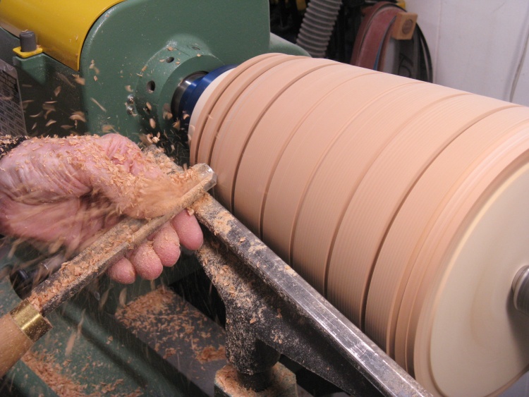
Removing excess wood
...and then the extra wood between the bases of the slots was removed, mostly with this roughing gouge.
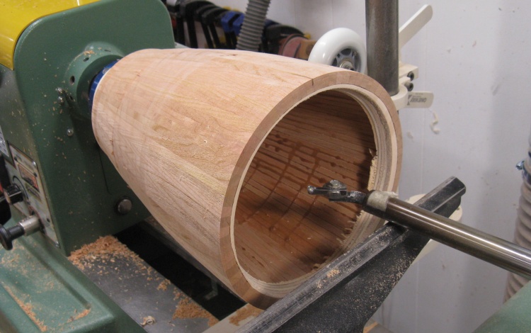
Cover off and ready to rough-cut interior
Once the first crude outside shaping was done I thought I'd better do a bit of inside work.
I cut through the cover and floor plywood discs to release any stresses they may be adding. I then did a rough rounding of the inside to improve the balance.
I cut through the cover and floor plywood discs to release any stresses they may be adding. I then did a rough rounding of the inside to improve the balance.
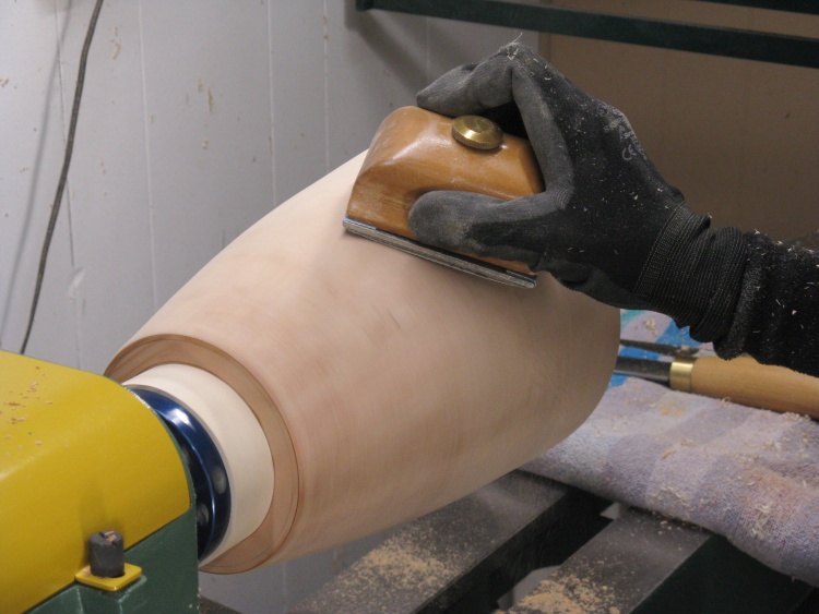
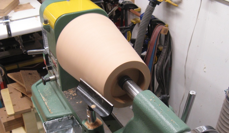
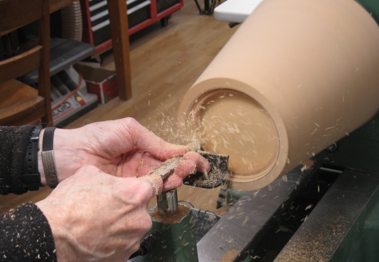
Finishing off the outside
The outside could then be shaped and sanded with this photo showing the first round.
When it was done I wasn't very satisfied with the finish (due to some chipped areas) so I took off a bit more wood and re-sanded.
When it was done I wasn't very satisfied with the finish (due to some chipped areas) so I took off a bit more wood and re-sanded.
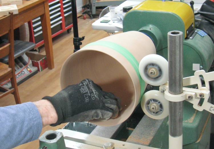
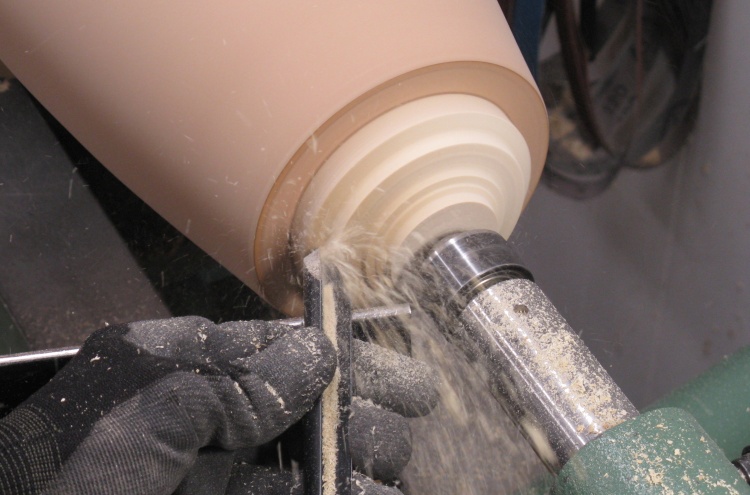
Starting inside thinning
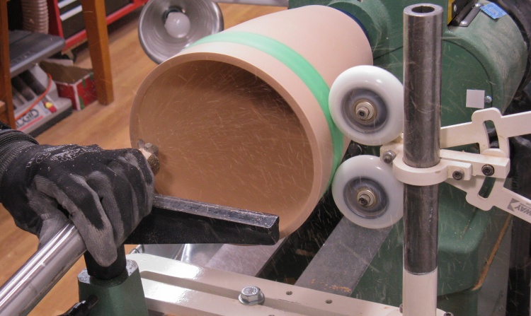
With the outside shaping done, I switched to thinning the walls from the inside.
The green ring around the vessel is a strip of taped-on plastic that prevents the stabilizing wheels from indenting the wood.
The green ring around the vessel is a strip of taped-on plastic that prevents the stabilizing wheels from indenting the wood.
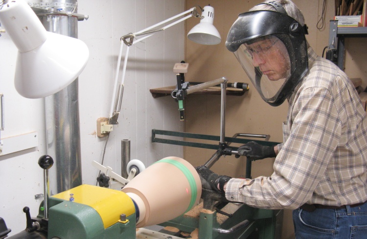
Very serious-looking turner
This is a shot of the hollowing setup with the captured hollowing jig and a laser spot showing cutter position.
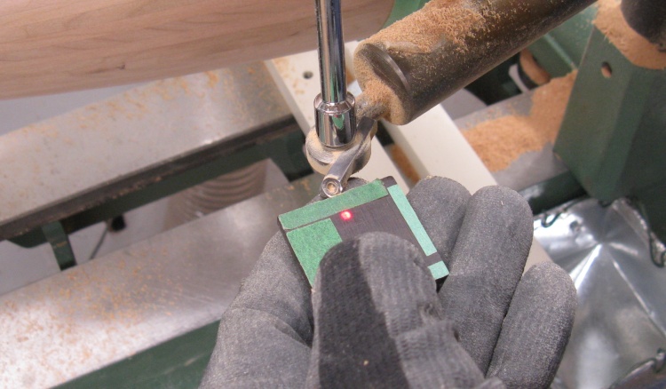
The main cutter used for hollowing
I mostly used this tiny carbide cutter to do the inside turning. Here I'm checking the position of the laser dot using the little black jig.

The small cutter leaves a pretty rough finish
The carbide cutter works well but the small size (or maybe me using the small size) leaves a pretty rough surface.
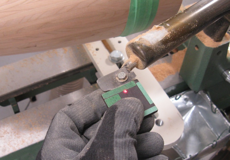
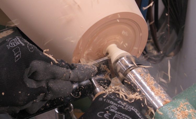
Using a wider cutter to smooth walls
To smooth things out, I would switch to a much wider cutter and take a light pass over the walls as a finishing step.
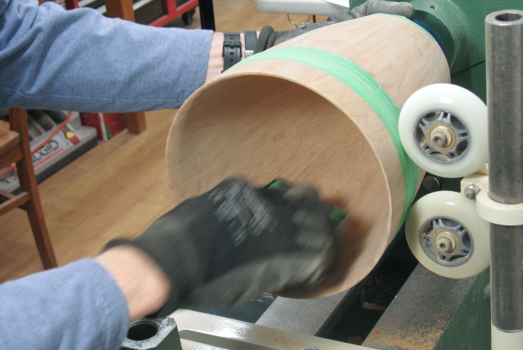
Starting on the inside sanding
And then the inside was sanded. I started with a coarse grit on a rounded form and spun the vessel to level out the most egregious bumps.
Switch to sanding with the grain
Sanding around the diameter as above leaves fairly obvious scratch marks since the sanding direction is across the grain.
So then all those scratches needed to be removed by sanding with the grain direction using increasingly-fine grits.
So then all those scratches needed to be removed by sanding with the grain direction using increasingly-fine grits.
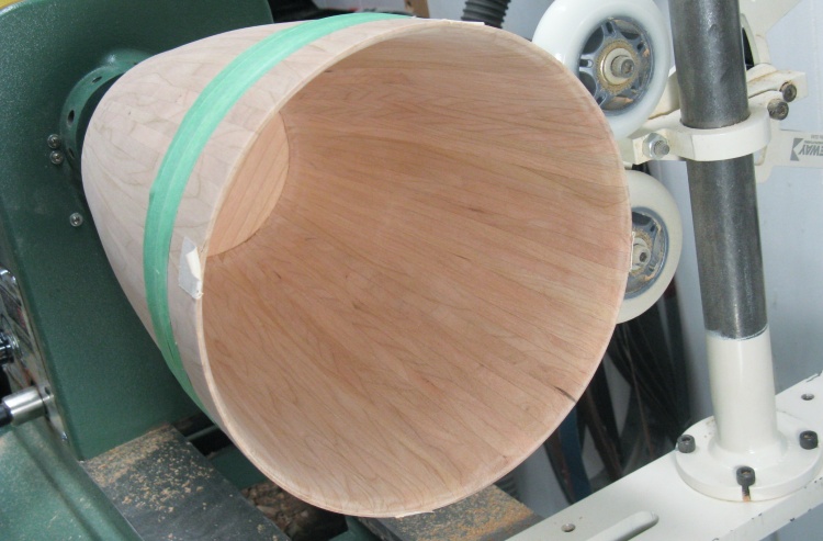
Inside sanding (finally) done
That was a couple days worth of sanding and let me tell you my right arm was very happy when it was done.
Inserting into jam chuck
The last bit was shaping the bottom.
I cut a slot to form a jam chuck to fit the top and then put the wastebasket in place with the tailstock pressing on the bottom to hold it firmly.
I cut a slot to form a jam chuck to fit the top and then put the wastebasket in place with the tailstock pressing on the bottom to hold it firmly.
Removing faceplate disc
Bottom shaping was started by transforming most of the faceplate disc into sawdust.
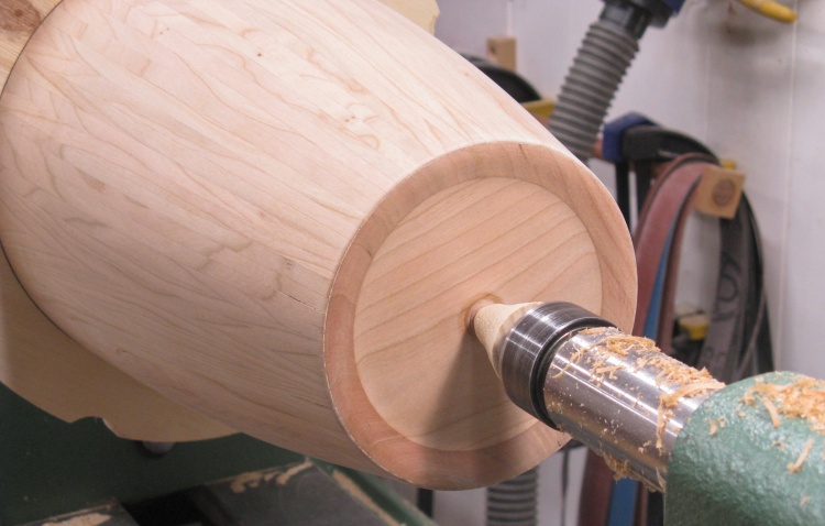
Shaping the bottom
Then the bottom was shaped; The edges were left thick to form a foot while the center area was removed down to the plywood.
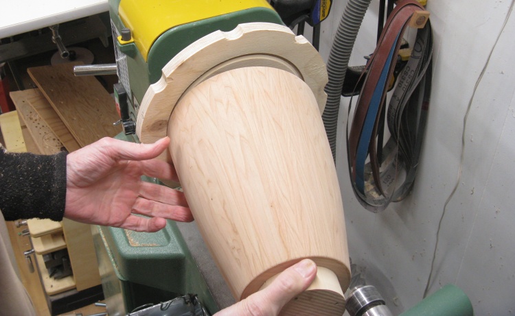
Bottom done except for middle bit
This shows the finished bottom after some sanding. That center bit just has to be removed.

Grinding down the middle bit
Once it was off the lathe and most of the bottom nub was sawn off, the remains were ground down using an abrasive bit on a Dremel rotary tool.
That was followed up with some Dremel-sanding-disc work which smoothed off the grinding remnants and then hand sanding did the final smoothing.
That was followed up with some Dremel-sanding-disc work which smoothed off the grinding remnants and then hand sanding did the final smoothing.

Woodworking done
That's pretty much it for the woodworking. The last bit was to add initials and the year to the bottom.
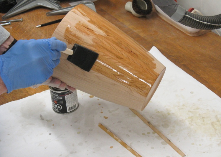
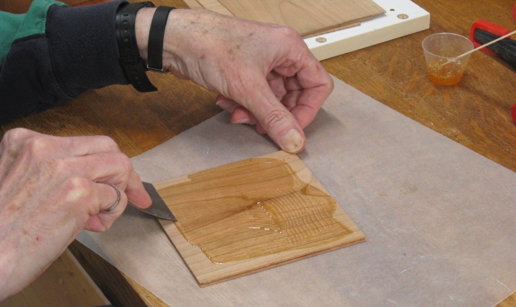
Starting on the varnishing
The varnishing was pretty straightforward. I used three coats of Minwax Fast-Dry Poly in Satin finish (or technically "Warm Satin" since a recent re-branding).
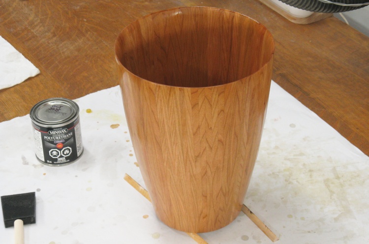
First coat of varnish soaking in
As usual, the color popped out nicely with the application of the varnish.
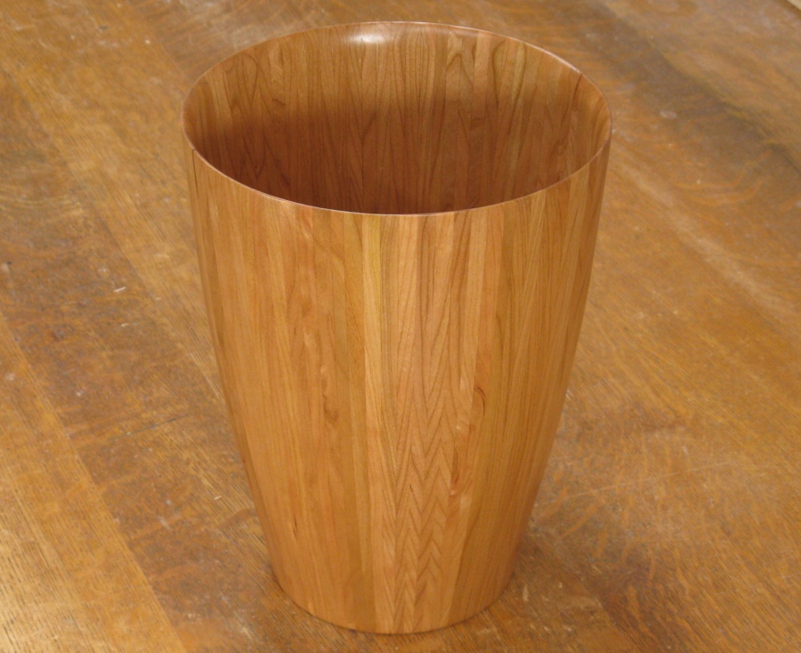
Completed
Done
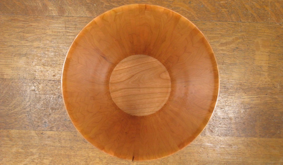
Top view
Looking in.
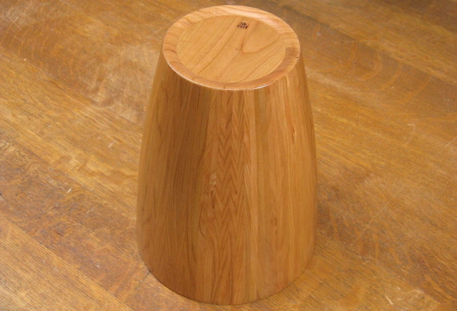
Bottom detail
Downside up.


