
|
Warning! Long post - apparently I need an editor (or simpler projects).
Details
I found years ago that it was a big pain to gather everything required to change tires on the car which at the time we did on three vehicles. You need the right size sockets, the breaker bar, the torque wrench, etc. - about a dozen items to round up.
Imperfect season-to-season memory often led to a trip or two or three from the garage inside and downstairs to find the forgotten item, and then of course everything needed to be put away again until the next car. Having everything in a dedicated case was a huge boon - I pretty much just grab that and I'm out the door.
Later I bought both a cordless torque wrench and an inflator to simplify things further. Of course the shapes of those tools are different than the old ones so they wouldn't fit in the original case without heavy modifications. Plus there was that sticky-outy torque-setting wrench issue too. I did honestly try to find a commercial case that might work, but most are square-ish while longer specialized ones like rifle or fishing rod cases were much too long. Musical instrument cases didn't work out either so it was time for a "roll your own".
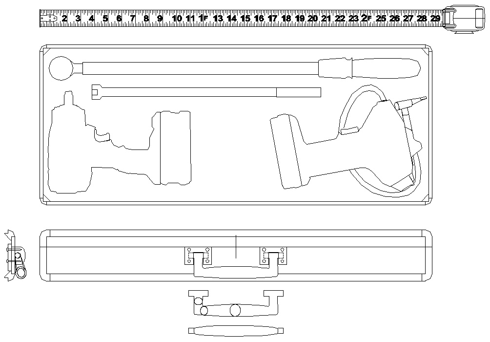
The case, so long that I had to use the virtual tape measure

Most of the case design was done with 3D modelling
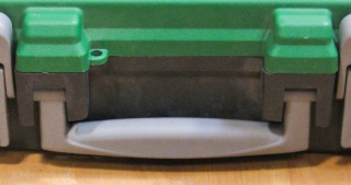
Original Plastic Case
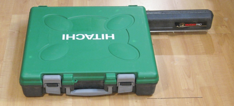
The original case
The original case was this rather oversized green beast that my Hitachi cordless drill came in. I managed to fit everything I needed into it except for the torque-setting wrench which was a tiny bit too long.
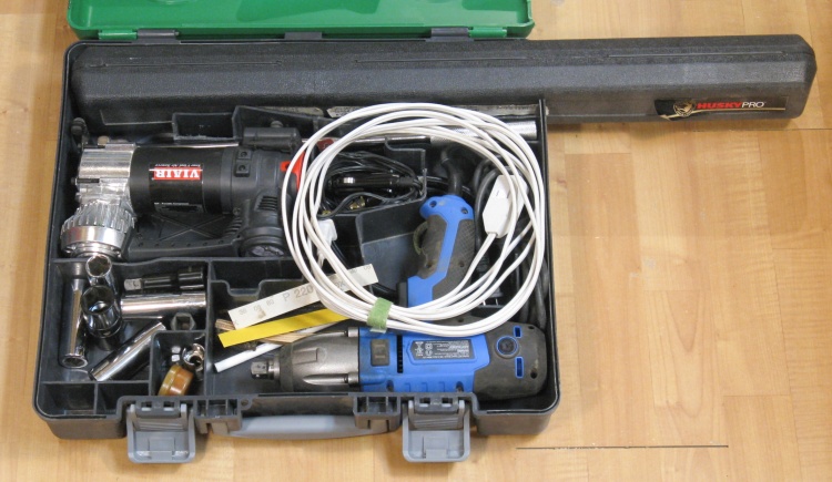
Packed full of goodies
Ruthless removal and/or modification of the original internal walls and their relocation resulted in appropriately-sized cavities for everything (except perhaps the extension cord). But it was a great system and deserved to be replicated with the next generation of tools.
Frame
I suppose one could theoretically make a wooden case using something like tongue-and-groove planks but really the only practical solution for large flat areas is plywood. It probably would have actually made a better case by using plywood exclusively, with box joints at all the corners (simpler and stronger too) but I wanted rounded corners and chose to make a frame to achieve that.
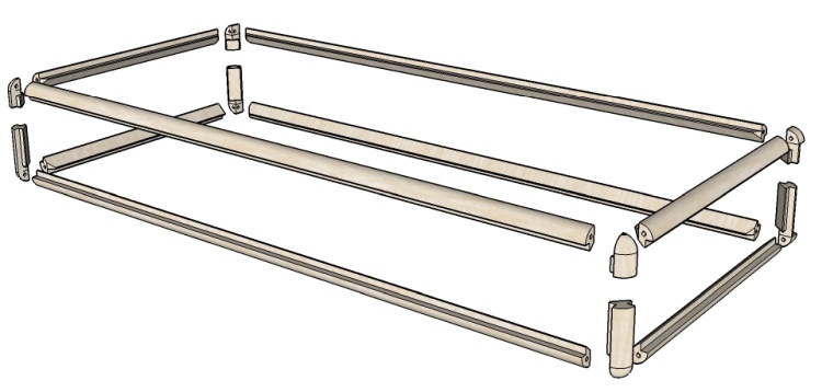
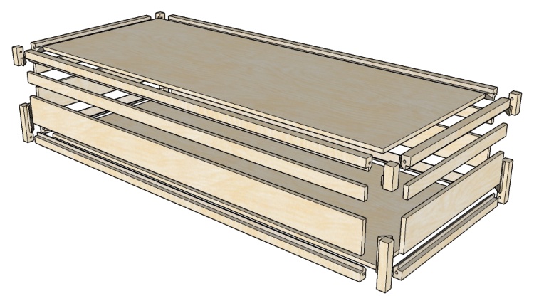
The frame is pretty much just all the corners
This shows the 16 pieces that comprise the frame of the case. In this image they are rounded on the outside as they will be on the finished unit, but they will actually be made with square corners for easier handling and then rounded after case is assembled.
Two pieces comprise each short corner of the frame, but to avoid fiddly short bits of wood they will be made as extra-length single pieces and then cut apart later.
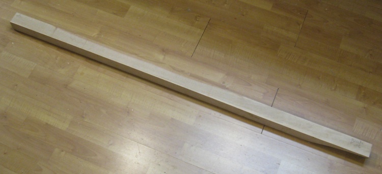
A piece of birch suitable for the frame
I planned to use 1/4" Baltic Birch plywood for the sides so it seemed logical to use Birch for the frame as well. Fortunately I had some longish pieces that had been languishing on my wood shelves for about five years.
This one piece with a 2" square cross-section will be mostly used up making the frame.
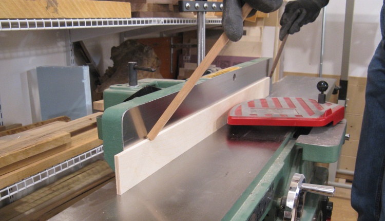
This underwent the standard operations to get a big chunk of wood down to smaller chunks of wood;
Cutting three lengths off

Jointing flat on two sides
Cutting into four smaller pieces

A collection of roughly-sized frame pieces
The output of the above operations was this group of a dozen pieces that included long pieces for the long sides, short pieces for the short sides and medium-length pieces to be cut up to make the corners.
These are all a bit oversized to allow for machining that will leave them with a nicer surface and a correct-er size.
To get the frame pieces down to the final size of 0.75" square, I first jointed two adjacent sides so they were flat and square with each other. Then with these flat surfaces down, they went through the planer to get them to the final size. Usually I need to worry about planer-caused snipe where the ends get thinned a bit more than the rest of the board but for my non-critical application I was able to ignore this 0.005" difference.
Flattening individual pieces
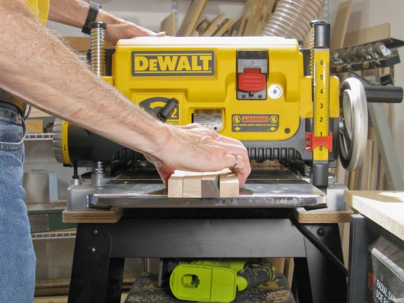
...and planing to size
A collection of precisely-sized frame pieces
All the pieces are now straight and flat as is evident in this mostly-gap-free arrangement.
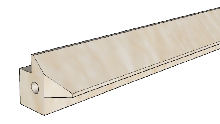
What the profile of a frame piece should end up looking like
The square profiles of the pieces shown above need to be transformed to match this image which shows the profile of a frame piece. The lower left corner will eventually become a rounded outside corner of the case. The end includes a hole for a small pin to join it to the corner piece, and a bevel to match up with the adjacent side piece.
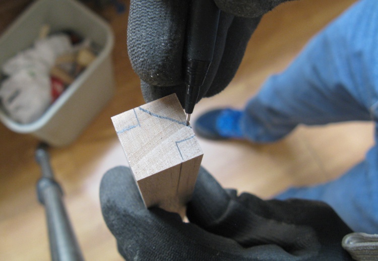
Marking an end
I started by roughly marking all the pieces to help prevent the inevitable screw-up guide me in machining the correct faces.
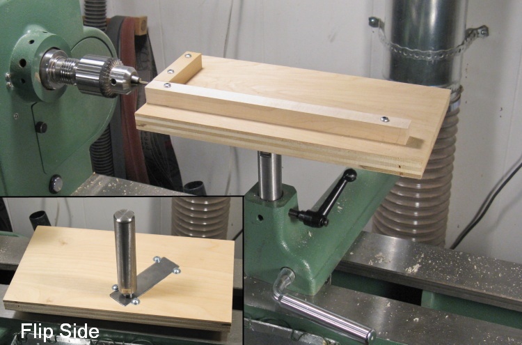
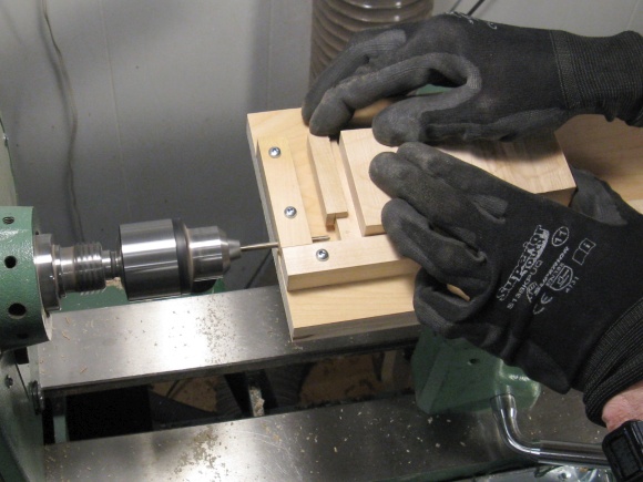
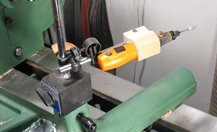
A newly whipped-up horizontal drilling jig
Jig Time!
I was going to need to drill the ends of the long frame pieces, something tough to do on a drill press. Instead I made a horizontal drilling jig for the lathe which was just a suitable framed surface mounted to a screwed-on attachment for the lathe banjo (AKA tool rest base).
The surface was just maneuvered into position relative to the drill bit to get the correct drilling location relative to its base and fence. Then it was locked into place.
The alignment was actually a pretty fiddly process to get right but when locked in place, the jig was very stable.
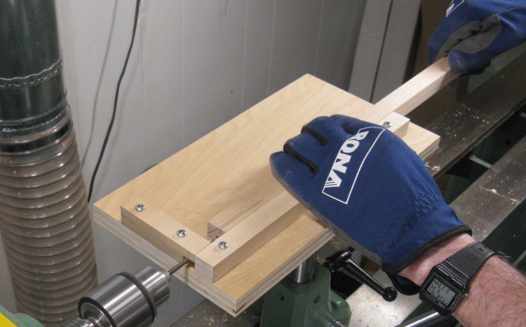
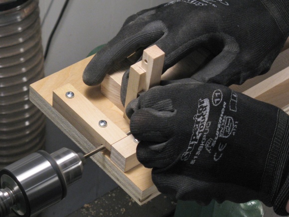
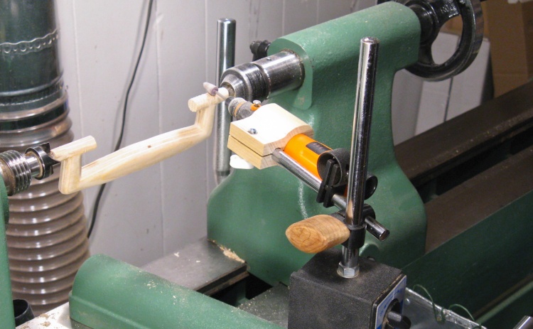
Drilling a pin hole in the end of one of the frame pieces
Here I'm drilling one of the long frame rails. The wood is held against the side fence and pushed into the drill bit. The front fence position relative to the drill bit tip determines the depth of the hole.
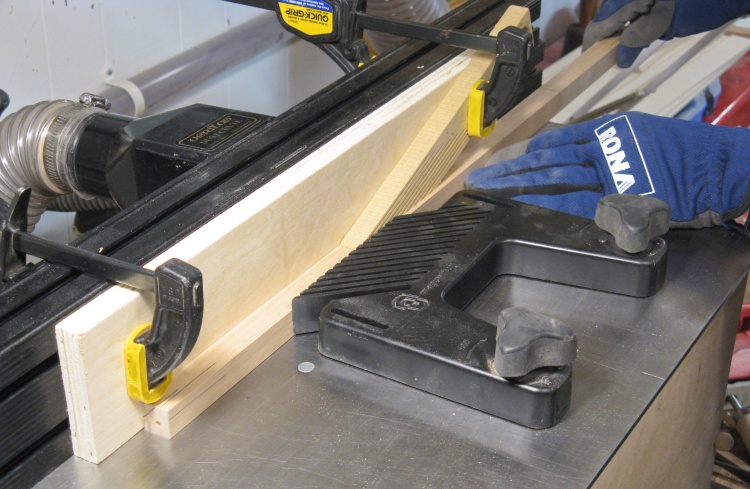
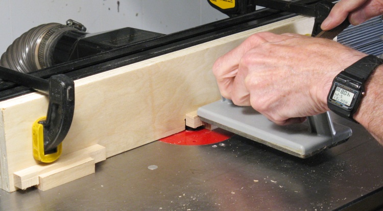
Starting to route the corner slots
Next step was to route the corners; two opposite corners both needed a 1/4"-square notch to accept the plywood walls.
I routed off only small amounts of wood each time, working up the full 1/4" depth. The two featherboards provide pressure to hold the wood against the bit as it is slid through.
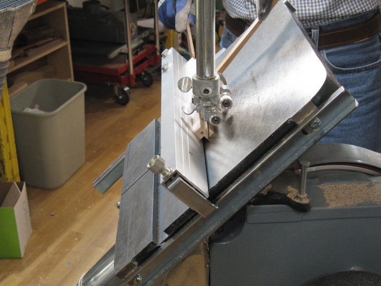
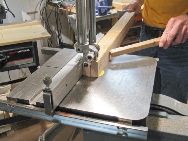
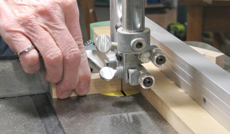
Cutting the 45° angle on one corner
Then the corner that would be inside the box was cut off at a 45° angle on the bandsaw.
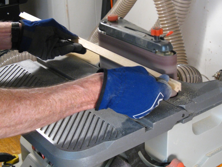
Sanding off the saw marks
The bandsaw always leaves a rough surface so that newly-cut bevel was smoothed out using the horizontal belt sander.
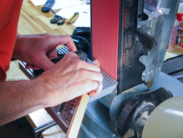
Using the belt sander for bevelling the end
And in the final operation, a bevel was sanded at each end.
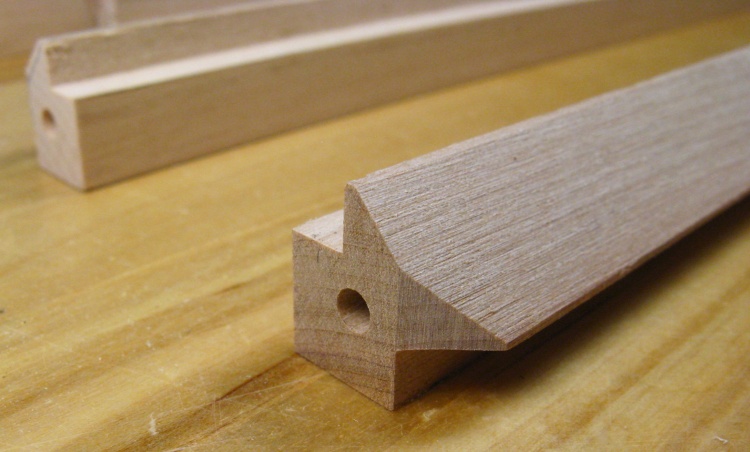
And voilà: frame profile done
This shows the completed profile of one of the frame rails.
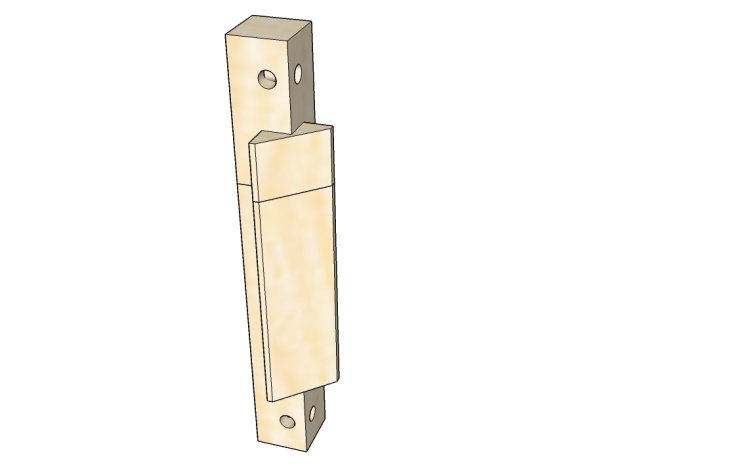
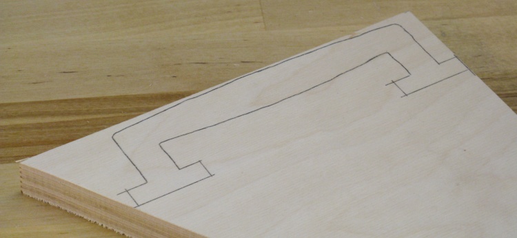
The shape of a corner piece
The short-corner frame pieces were a bit different; they had the same 1/4" grooves with a bevel between them but the "wings" of the bevelled parts stop 3/4" from the end. And the ends of course have pin holes to match the side rails.
While two separate pieces will be needed on each corner (for cover and base), I made them as a single piece to simplify things. This illustration shows the dividing line between cover and base pieces, but I'll have extra length that will make that dividing line about 1/4" wide to provide some space for cutting them apart later.
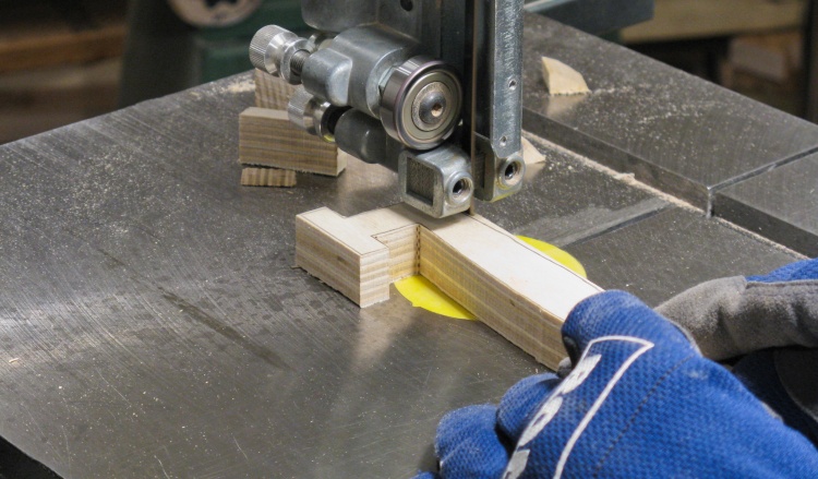
Cutting one way...
Those medium-length frame pieces were cut into 4" lengths for the corner pieces. I started by making a shallow cut at the end of the bevelled areas on two sides.
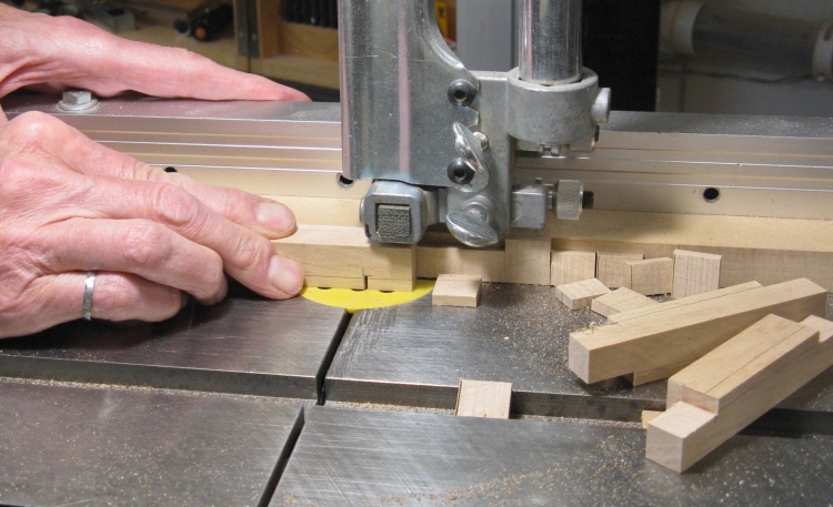
...and the other way
Then the unwanted bits were cut off from the ends. You can see a couple pieces that have been done already.
I cut the protruding sections a bit fat so later I could more-accurately machine them to the proper width (and get rid of the nasty saw marks to boot).
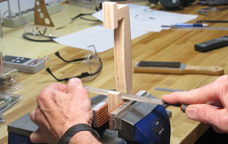
Then routing in the corner slots
The next step was to route the 1/4" grooves in opposite corners. This was done in the same manner as the other frame pieces, except these were too short to use the featherboards.
Again I took only small cuts on each pass and you can see from the piece on the left that I'm almost to the 1/4" depth at this stage.
Then it was back to the horizontal drilling jig to drill the holes. Technically these could have been drilled easily on the drill press but the jig was already set up for the proper hole location relative to the edges.
Drilling pin hole in one side...
...and the other side
Corner Pins
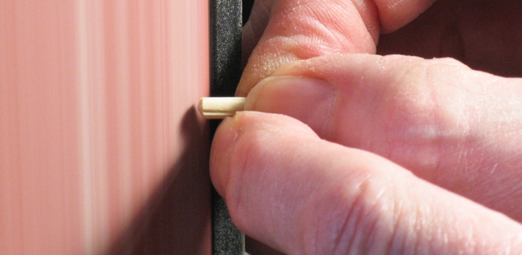
Kinda fits in like that
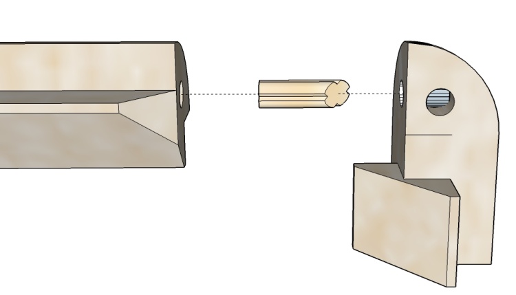
The ends of the frame rails are end grain which does not glue well, so I added some small pins to increase corner strength a bit. The pins need to be pretty small - 0.15" diameter - and pretty short - 1/2" overall - but even if they have little effect on the strength, they act as rail-to-corner alignment guides.
This illustration shows the grooved and bevelled pin as it fits between corner and rail pieces.
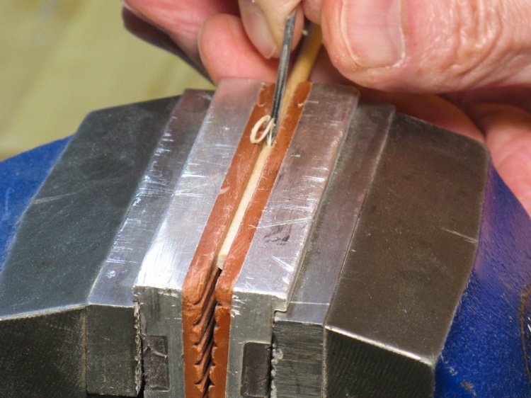
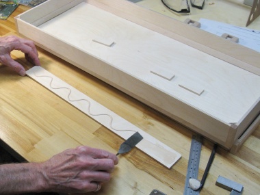
Cutting a groove in a small dowel
I happened to have dowels of 0.15" diameter so those became the raw material for the pins. Usually joint pins are grooved to increase glue area and prevent an airtight seal. My dowels of course were smooth so I used a tiny V-groove tool to carve four grooves along the length.
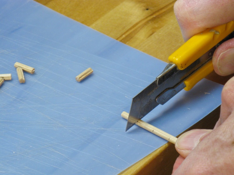
Chopping up the dowel
The dowel was small enough to just cut apart by rolling under a sharp knife.
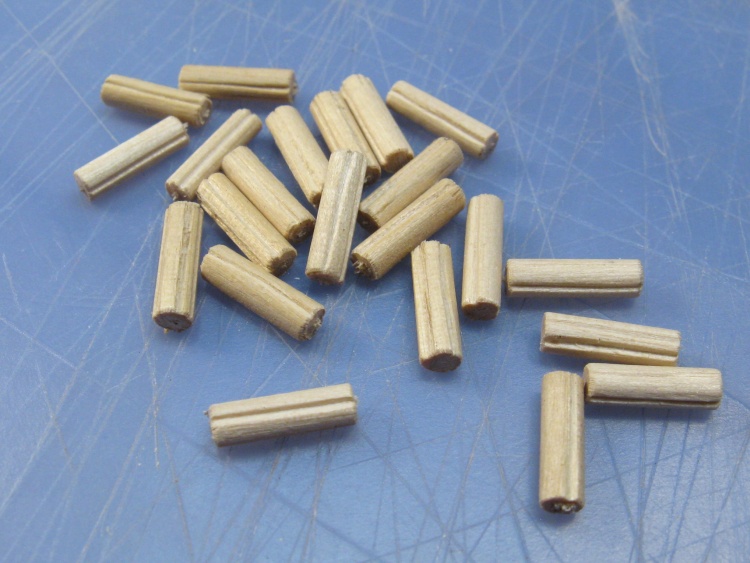
A little collection of pins (1/2" long)
It didn't take long to make the 16 pins that would be needed (and some spares).
Bevelling the end of a pin
I realized after the family photo above that the pins were close enough on the adjacent sides of the corner pieces that they would interfere if the ends were left square.
To fix that they got a 45° bevel on one end, courtesy of the belt sander and some careful holding to prevent a nasty manicure.
Walls

1/3 of a full birch plywood sheet
I'm not sure if this is common practise, but the local Windsor Plywood usually cuts full sheets of Baltic Birch plywood into three pieces. The sheets are 60" square so the 1/3 sheet is 60x20".
I bought a one-third sheet of 1/4" thickness, which would be enough for the case.
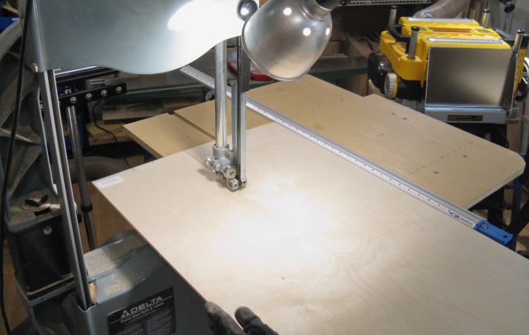
Cutting to width on the bandsaw
I started by ripping* a strip with a width equal to the short dimension of the case. Here I've attached my sheet-goods table extension to the bandsaw, a necessity for the tablesaw-lacking woodworker.
*Opinions vary as to whether "ripping" means cutting parallel to the grain or just in the long dimension of the wood. The first definition is problematic for plywood since it has grains in both directions so I'm using the latter definition here. But for the strict parallel-cut grammarians, I'm 3/5 ripping and 2/5 crosscutting based on the plywood layers. Ripcutting maybe?
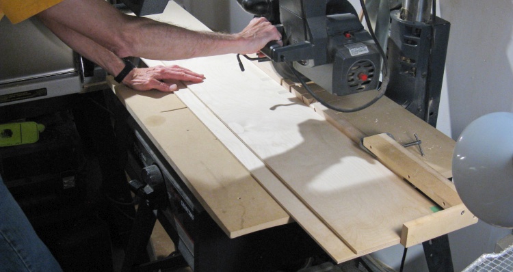
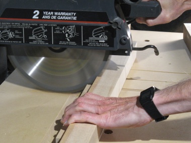
Chopping to length on the radial arm saw
My two narrower strips were crosscut* to the proper lengths using the radial arm saw, equipped with a makeshift stop to determine cut length. Maybe I should make a "real" stop some
day...
*Yah, like above, but the opposite.
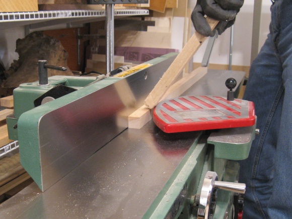
Flattening edges
The edges cut with the radial-arm saw were nice and smooth but the bandsaw-cut edges needed to be cleaned up by using the jointer.
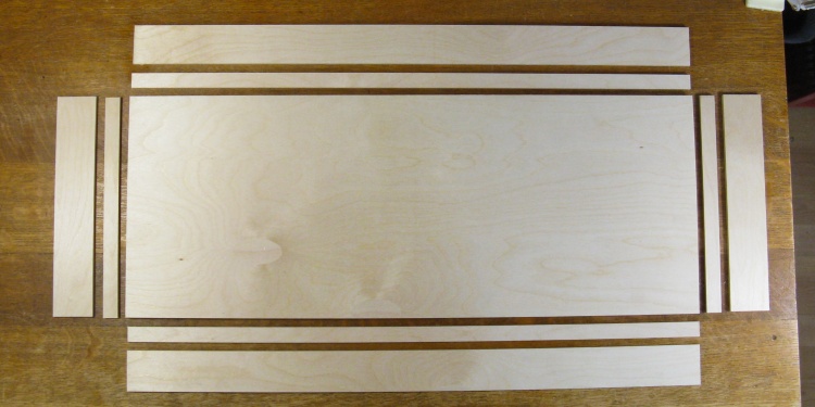
The complete set
In fairly short order I had all the main pieces cut. They included the top and bottom (stacked together here) plus wall pieces for the cover and base.
Handle
A nice curved handle that I didn't bother to make look like plywood
I had envisioned a folding handle similar to the original incarnation of the case but I couldn't find suitable commercial hardware. Oh well, I'm retired; I'll just make my own.
Like this one
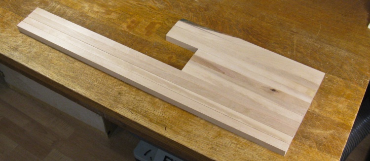
Handle shape traced onto 13-ply 3/4" plywood
The handle needed decent strength in all directions, so solid wood wouldn't have been a good choice. Instead, I used a 3/4" piece of Baltic Birch plywood. This is decent stuff with 13 plys and few voids.
Here the handle shape has been traced onto a plywood scrap.
Cutting handle to the lines
The first step was to cut out the handle close to the line using the bandsaw.
A bit of shaping with the file
The edges were cleaned up to be smoother and closer to the lines by sanding or as seen here a bit of filing.
Then once the outline was right I went ahead and shaped the handle using the belt sander, a small drum sander and finally sanding with sandpaper strips.
Main shaping
A bit more-detailed shaping
...and some sanding
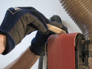
Time for another jig; Lathe Grinder
Jig Time!
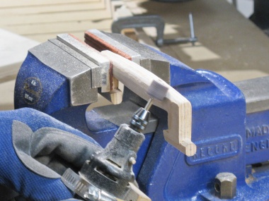
I wanted the "T" ends of the handle to be 0.4" diameter and nicely round so the handle swings easily. However, it's tough to hand-shape things consistently round, so I looked for better method.
The method was to mount the handle between centers on the lathe so it could be manually turned. Then I needed something to firmly position a grinder a specific distance from the center line.
My solution was to use a magnetic base for a dial caliper but with the calipers replaced with a custom clamp for a small cordless grinder. The result is shown here. The base allows the grinder to be properly positioned and the thumbscrew provides a way to precisely move the grinder.
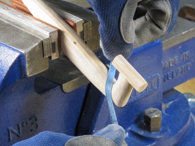
Handle was turned manually to round the pins
The handle was mounted between centers on the lathe and the grinder positioned to remove a small amount of wood. Then with the grinder running I rotated the handle manually to grind a narrow but nicely round channel in the wood. Then the grinder was positioned further along by repositioning the tool rest base and this was repeated.
Of course the handle couldn't be turned quite all the way around when grinding beside or inside the handle, but I could get most of the curve and I then sanded the untouched parts to match.
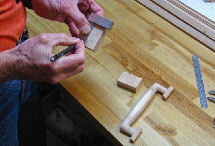
Handle done, now marking pin holder
With the handle done, it was time to start on a pair of holders to mount it to the case.
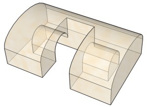
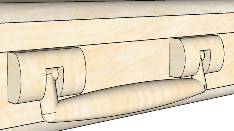
Holder, translucent view
It would have been easier to make two holders for each side but again I opted to replicate something closer to the original case holders. I started by marking the areas to be hollowed on the bottom of a couple of birch holder blanks.
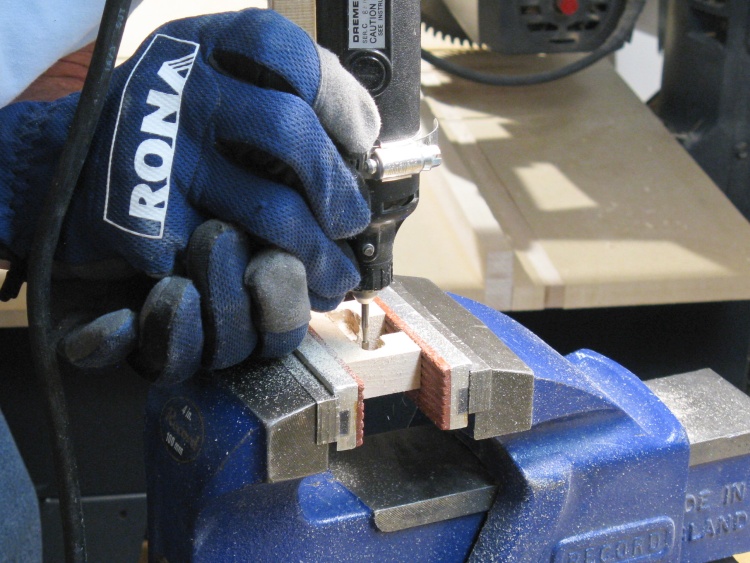
Hollowing out the holder to fit the handle pins
There was no good way to hollow out two blind half-round notches in the middle of the piece, so that just left the bad ways.
Like the Dremel with various bits, small chisels and dogged perseverence. Oh, and a high tolerance for a rather crude-looking result. That combination eventually won out.

Shaping a pin holder
Once the bottoms were hollowed, I shaped the top and sides on the belt sander.
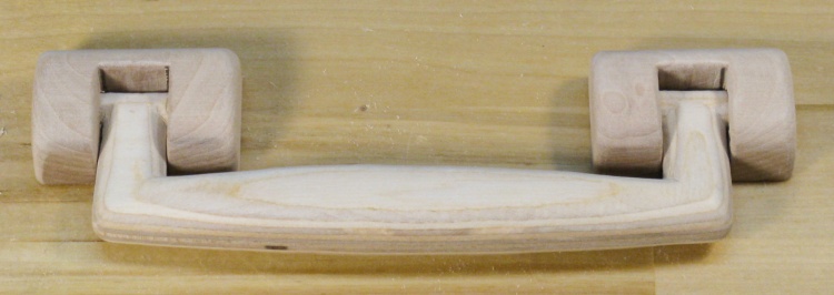
Handle and holders
This the end result after some shaping and sanding. You can't even tell that the bottoms look like they were dug out with a slot screwdriver.
Assembly
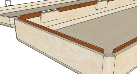
A few pieces need to go together
With most of the parts made, it was time for assembly. This sketch shows the parts that will go together for the initial assembly stage.
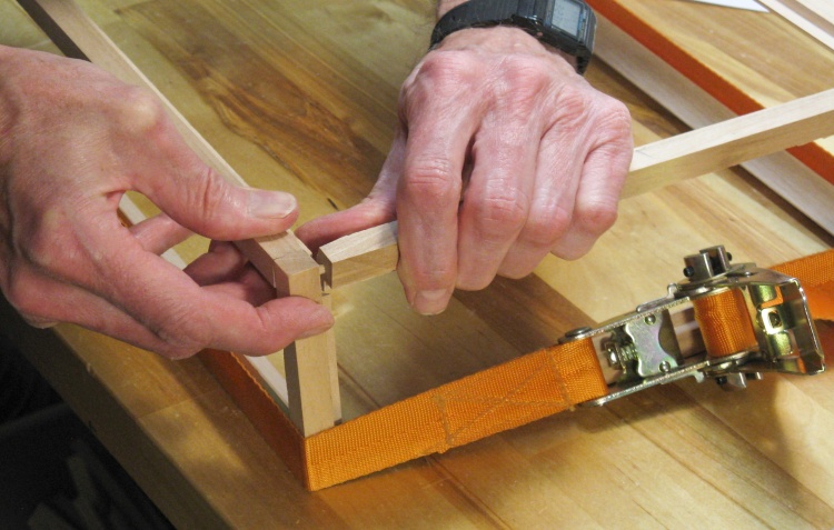
Doing a test fit
I started by doing a dry fitting. The ratchet strap holds one side together while I assemble frame pieces for the other side.
The frame pieces have pretty small flat surfaces so it looked like it was going to be tough to ensure that (or even tell if) the frame pieces were square when they were glued.
Gluing a wall to a corner
To help ensure squareness, I decided to first glue the side walls to the frame pieces. Then having the attached side walls up against the short corners should ensure the frame pieces are square.

Rechecking the fit
This is the new dry-fit, now with attached walls.
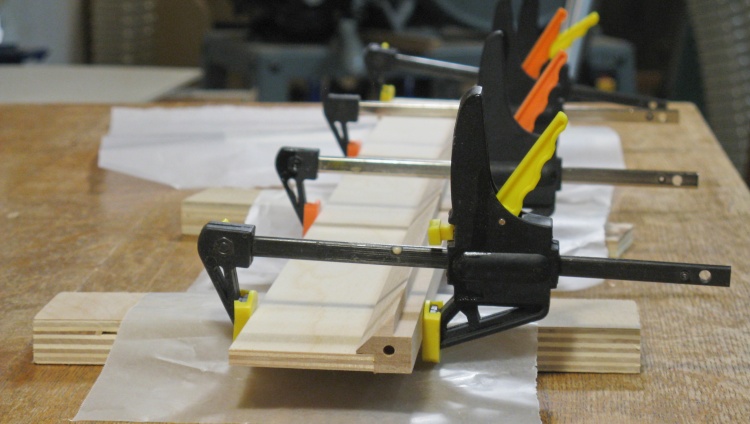
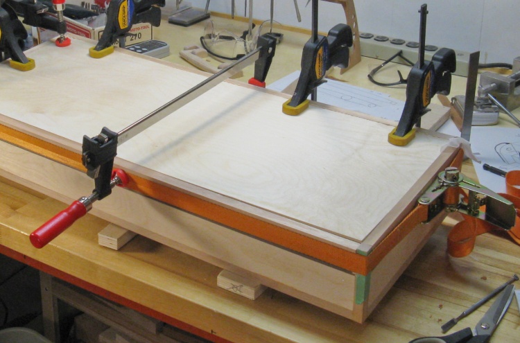
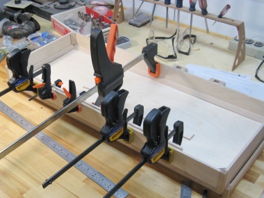
Bottom glued and clamped
Then it was a matter of gluing things together. To limit the number of surfaces to glue, I did only two frame pieces at at time. Here the last two pieces of the bottom portion of the case are being clamped as the glue dries.
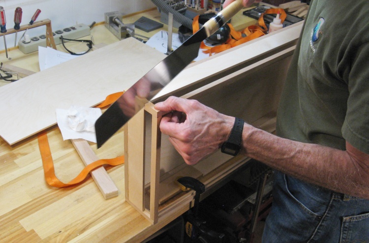
Chopping through two opposite corners
The rest of the case (the cover portion) is still together but without glue. Having it in place while the bottom portion of the case was glued ensured that everything stayed aligned during the gluing.
But now I needed to be able to disassemble the cover to glue it except the corners were now glued in place so there wasn't any give. I needed about 1/4" of play to be able to pull the frame pieces off the pins. To get that room, I cut through two diagonally-opposite corner frame pieces and taped them back in place.
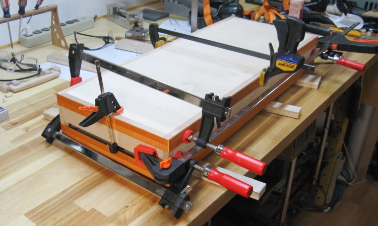
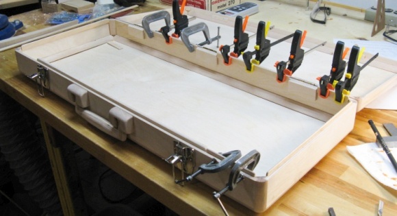
Gluing half the second side
Then the cover portion was glued, doing it two pieces at a time like the bottom.
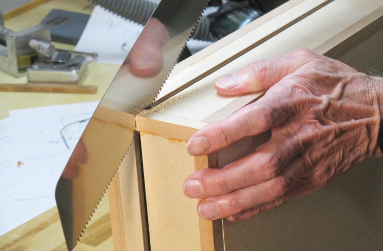
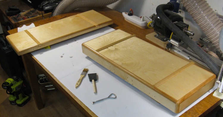
Cutting apart bottom and cover
The bottom and cover were separated by cutting through the two remaining solid corner frame pieces.

Two pieces!
This shot shows the bottom and cover pieces, post-separation.
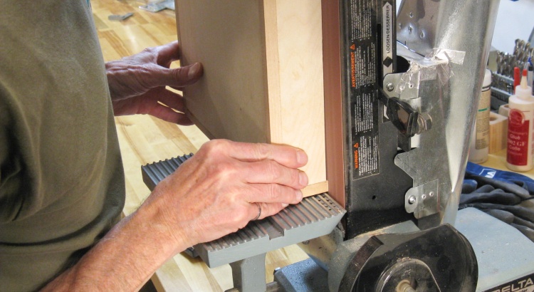
Sanding the corners flush
The extra length left on the corner frames was sanded flush with the walls using the belt sander.

Reinforcement pieces needed for handle, latches and hinges
There were a few more pieces to go into place. The first set were reinforcements for the handle, latches and hinges. They provide extra strength plus enough wood thickness to take the mounting screws.
The reinforcements highlighted here are all made from the same 1/4" plywood as used for the walls.
The reinforcing plywood pieces were just cut to size and glued into place;
Applying glue to front reinforcement
Clamping that sucker on

Same for rear pieces
I also decided to cover the joints and for that I used 1/8" plywood.
Some joint coverage
...and the real thing
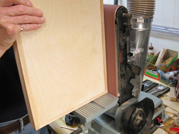
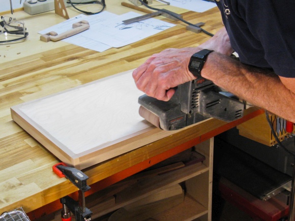
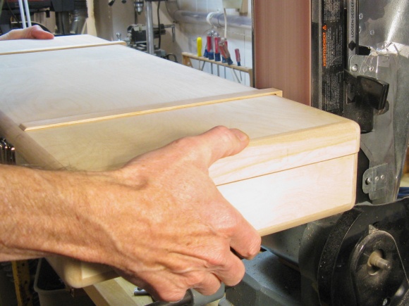
The case outsides were not perfectly smooth since the 1/4" plywood was actually 6mm so it didn't come quite flush due to the 1/4"-deep notches in the frame. But that was good since it meant I could sand a bit off the frame and bring it exactly flush with the plywood. I used the belt sander for the corners and short sides and then resorted to the little-used hand-held belt sander for the center of the long sides.
The hand-held belt sander is more of a remove-the-old-paint-from-the-garage-door type of tool but finds the occasional use in the shop.
Evening up the corners
...and the middles
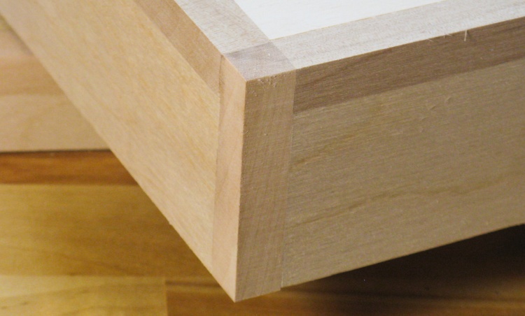
Corner after sanding
Things are nicely flush (and nicely glue-free) after sanding.

Routing the corners round
Next was (finally) rounding off the corners of the case. A 1/2" rounding bit on the router table did a nice job here. The wood scrap clamped to the end of the side prevents splintering at the corner.
I took four or 5 passes to get to the full depth of the cut.
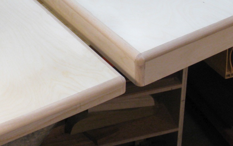
Rounded corners
This shows the newly-rounded corners on the cover and base.
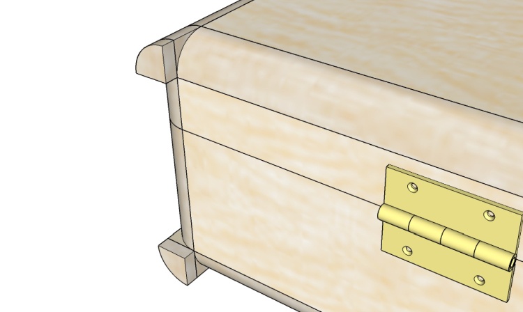
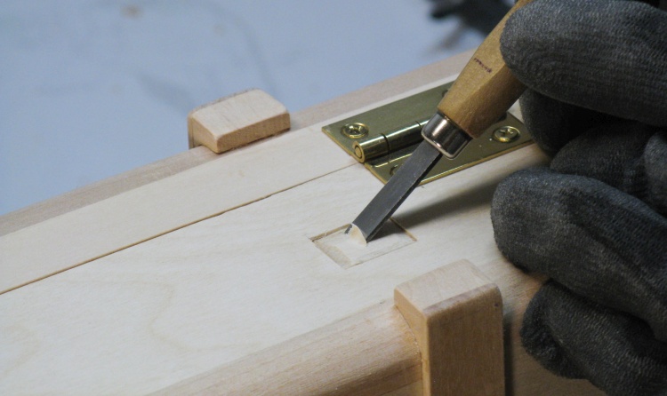
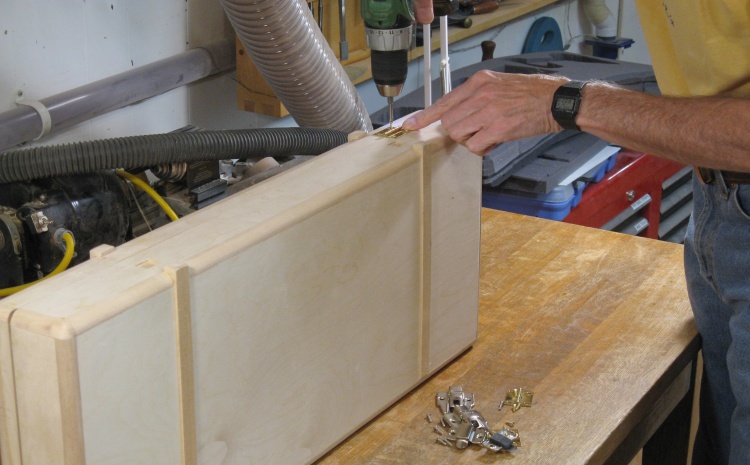
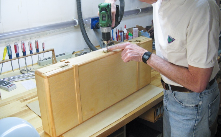
I thought I would install the hardware and see how things went together. Here I'm marking a hinge hole before drilling a pilot hole and installing the screws.
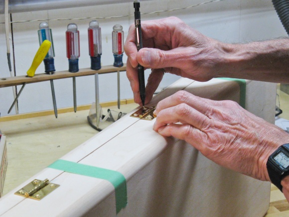
Marking for a hinge
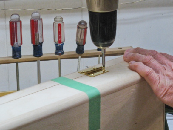
Installing a hinge
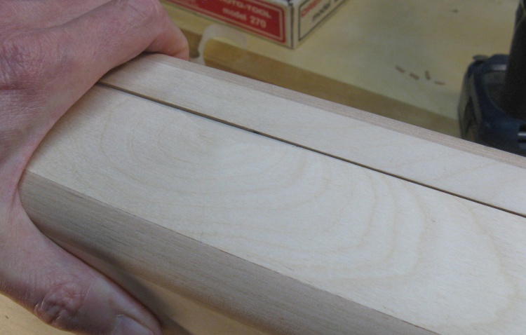
A bit of an overbite
Unfortunately despite my making the frame as a single piece so the cover and base WOULD BE EXACTLY THE SAME, there was a misalignment on the front. Sigh. Such are the vagaries of wood warpage.
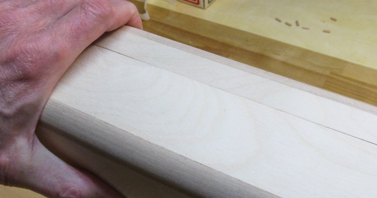
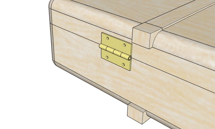
A more-even front now
Well, I kind of wanted the front to be right so I trimmed a bit off the back of the cover and that seemed to fix it.
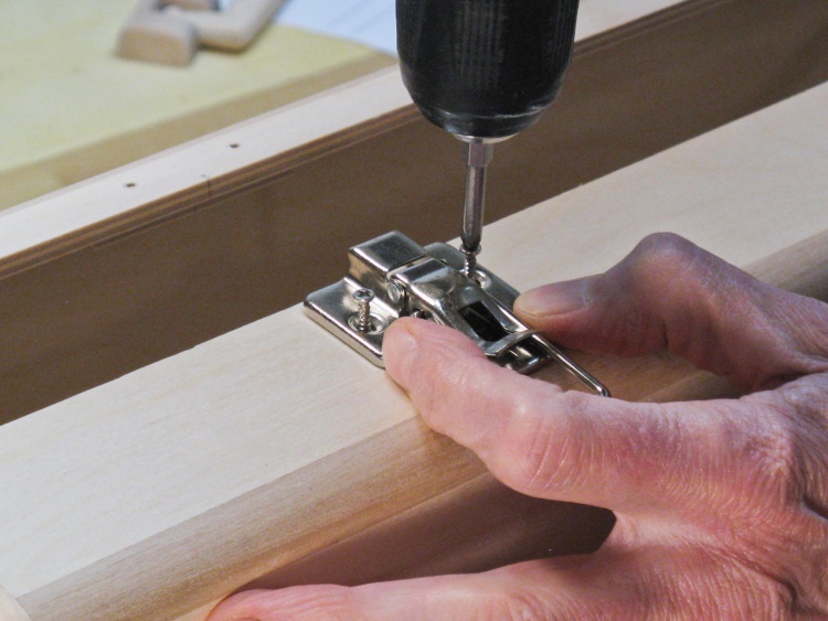
Installing a latch
So then with the front alignment OK, I could install the latches.
These are "draw latches" that pull the two halves together but when the pieces are touching, there is a fair amount of slop in the wire loop that holds them together. You could mount the pieces further apart, but that puts force on the mounting screws.
What's really needed is some spring or elastic providing a more-controlled force. They do make spring latches, but none I could find small enough for this case.
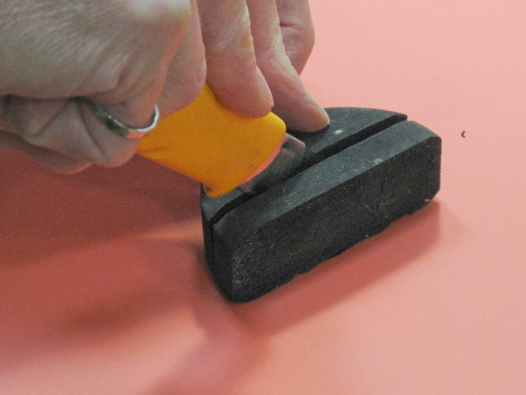
Puck surgery
I decided the elastic force would be provided by dense sponge. I sacrificed a sponge puck on the altar of quality latching action and here I'm starting to slice out its still-beating heart a suitable chunk.
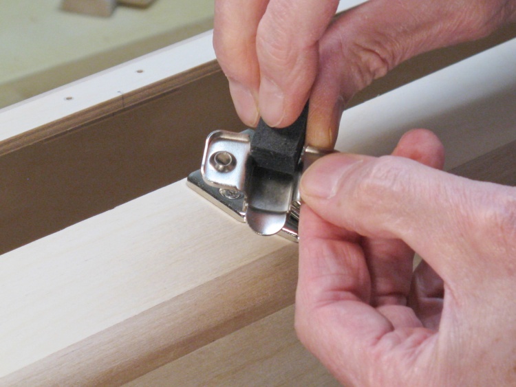
Installing foam into latch top
The foam went into the top half of the latch prior to installation.
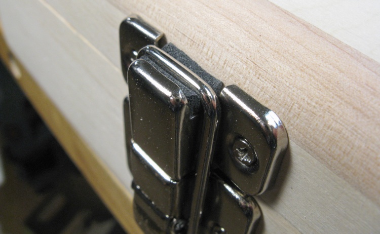
Assembled latch
And this shows the latch closed, with the wire bail pressing into the foam for rattle-free operation.
The original plan for corner feet
The original plan was to make four feet on the bottom, formed by selective rounding of the corner frames and an extra foot piece.
Unfortunately, that required me to not forget about them when I was routing the case corners. I forgot about them. So now the corners are nicely rounded in all directions and the case would teeter on the hinges.
The backup plan: middle feet
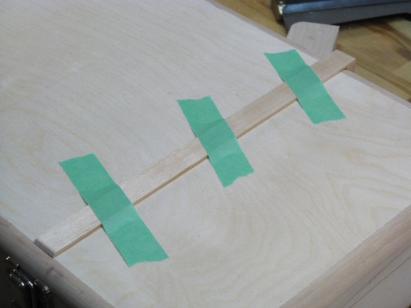
OK then. Plan B; add some feet to the side "straps" as shown here.
I could have made some feet for the corners that fit over the rounded frame but I thought these would be a bit easier to do.
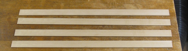
The "straps" ready to go
The "straps" are reminiscent of the buckled belts around old-style suitcases but obviously don't hold this one closed. Instead they act more like skid plates so only a small surface contacts the gritty garage floor where the case will typically be opened.
Here four straps about 0.1" thick have been made from another piece of birch.
I formed some feet from left-over 3/4" pieces from the frame, routing a concave section to fit over the rounded edge of the case. Then those feet were glued to the straps and the combined pieces glued to the case.
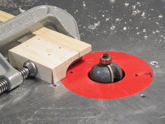
Forming a foot to fit the round edge
Strap and foot glued in place
I hadn't tried to make the foot heights exactly equal so after installation I marked a reference line on all four feet and then sanded them to size. The heights were tweaked so there was no rocking with the case set on a flat surface.
Marking for even foot heights
Trimming foot heights
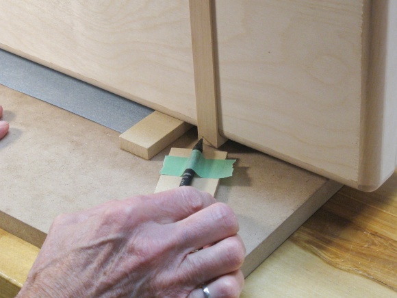
Carving out a foot recess
The feet needed to be long enough so the hinges were held off the ground. A consequence of this geometry is that the feet hit the back wall when the case is open 180° or less. I wanted the case cover to be able to rest on the floor which meant that it needed to open to at least 190° so I needed some recesses for the feet.
I marked the back of the case and used a small chisel to carve out rectangular recesses for the two cover feet. They ended up being pretty deep - almost 0.2" but then the cover opened wide enough without interference.
Woodworking done
That was it for the woodworking. Then I just needed to fill all that empty space in there.
Interior
Of course the tools would take up the bulk of the interior space but to keep them from banging around, the plan was to use a foam insert. I had bought 1" high-density foam and started by cutting it to the correct size and shape to fit into the case base and cover.
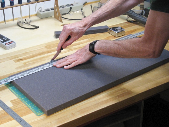
Slicing foam to size
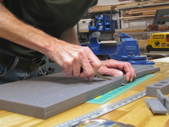
Bevelling corner to fit case
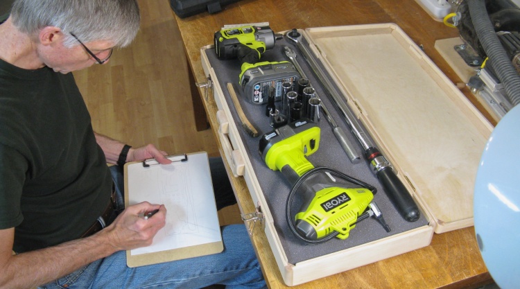
Working on the exact tool arrangement
I knew the basic layout but I tweaked the exact positioning of the tools and decided how to hold the sockets.
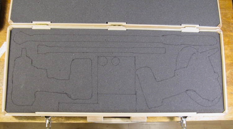
Cutouts marked
Once the layout was finalized, I used a fine felt pen to draw the outline of the tools as a cut-out guide.
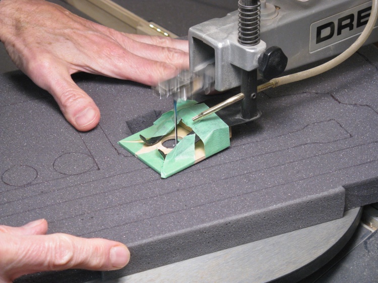
Using the jigsaw to cut out shapes
The knife I originally used to cut the foam was fine for straight lines but I needed a better method for the curved cutouts and settled on the bench-top jigsaw. I found that even a fine-toothed blade made rather rough cuts so I ground the teeth off a blade until it had a smooth sharp edge. That worked really well and gave nice clean cuts.
Here I'm cutting out one of the shapes using the jigsaw equipped with a jury-rigged plywood foot taped in place to hold down the foam.
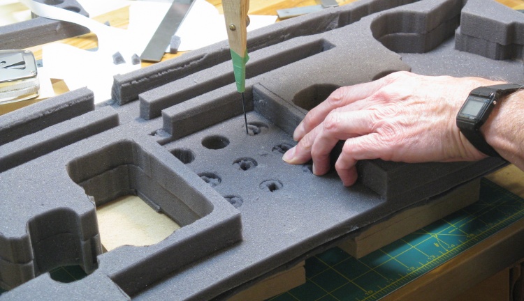
Cutting out the socket holes
It took two layers of the 1" foam plus another 1/4"-thick layer to get the correct height. In this shot, the foam shaping is completed except for the circular holes I'm cutting out for the sockets.
The foam shaping was rather crudely done but it worked just as well as perfectly-cut foam so I suppose I can't complain.
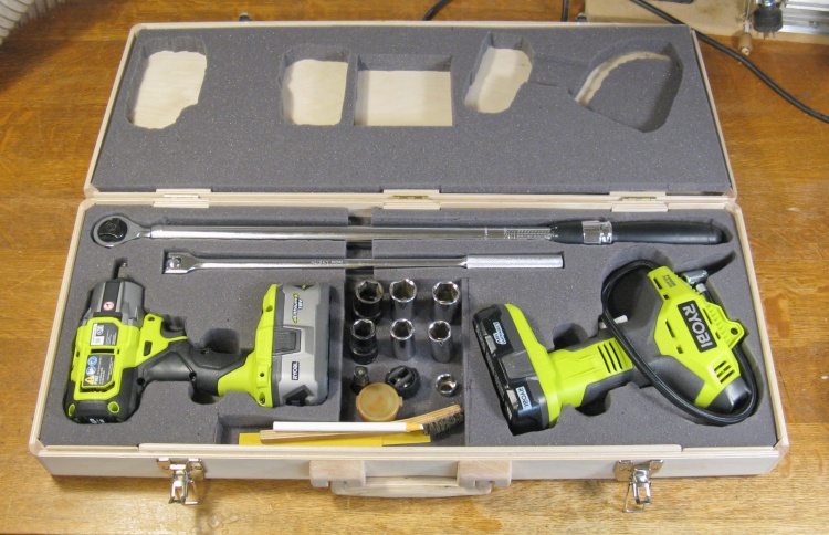
Foam done and case filled
The cover foam got a few holes as well and in this shot all the tools are in place.
I made space for the tool batteries but I won't store the batteries with the tools. That will leave them available for other tools.
Pulling it all back apart for finishing
That was pretty much everything done and the last step was to add a finish to the wood. But to do that I needed to remove the handle, hinges and latches.
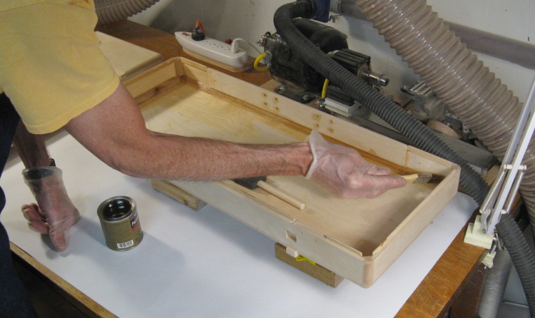
Starting on the varnish
I used my normal Fast-Dry Polyurethane varnish and this shot shows the first coat going on to the inside of the base.
First coat of varnish
The classic First Coat of Varnish shot. I used a total of three coats.
The varnish gave the rather pale birch a more-golden hue (which sounds much better than "yellowy").
Putting it back together
Once the last coat of varnish was dry, I reassembled the case.
The inside of the case had been made almost exactly the height needed to clear the largest items so the case walls were exposed in a number of spots. Rather than leave that as bare wood, I decided to add some thickish black cloth to provide some anti-rattle capability. I marked the exposed areas and then glued down appropriately-shaped patches.
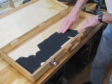
Gluing down cloth
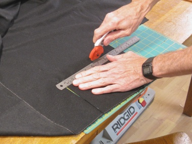
Cutting a patch
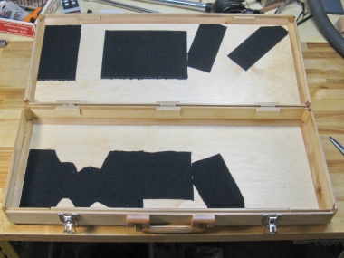
The full suite of patches
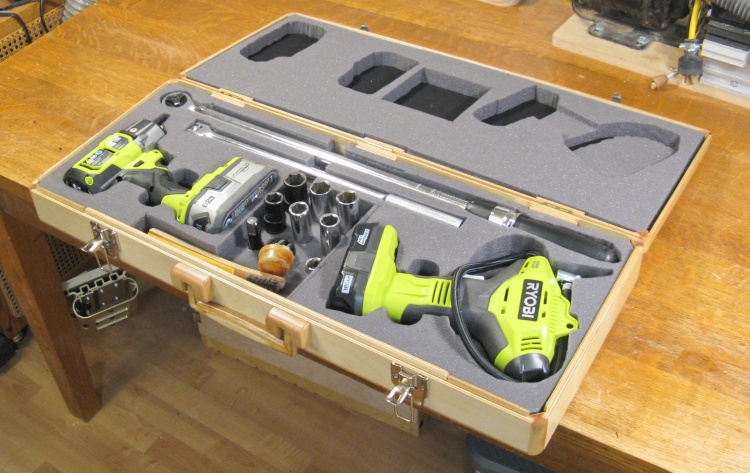
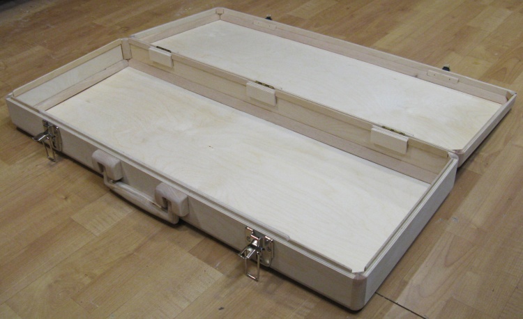
Done and open
The foam was glued into place as well, and that completed the case. This is the "open" view.
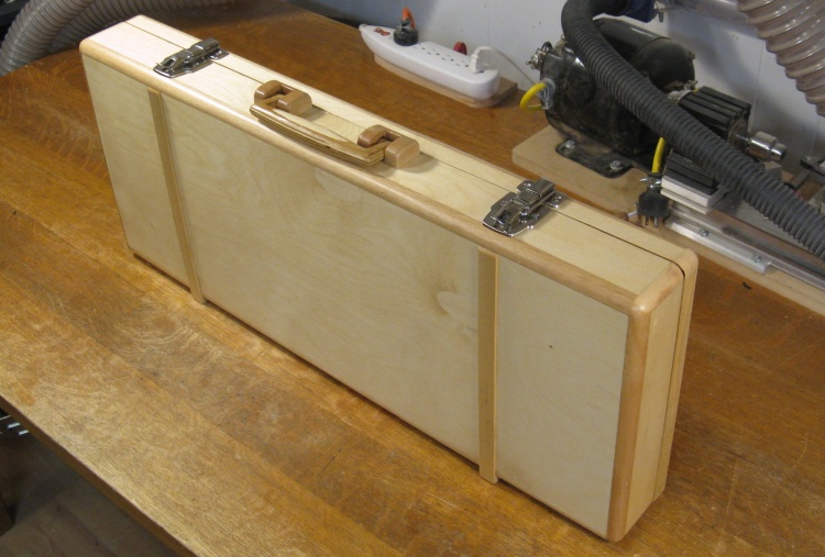
Done and closed
...and the "closed" view.
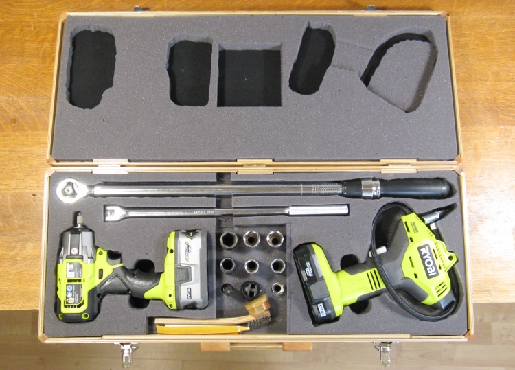
Contents
The case includes:
- Torque-setting wrench
- Breaker bar
- Impact wrench
- Tire inflation tool
- Impact & regular sockets
- Impact extension (for sockets)
- Scissor jack adapter for impact wrench
- Grease pencil to mark tires
- Wire brush and sandpaper for wheel hubs
- Grease for wheel hubs or bolts
I also added a label giving socket size, torque setting and tire pressure for the two cars we currently do tire changes on.


