The friend this viewer belongs to is a photography buff and includes among his endeavours stereoscopic photography and holography. This particular viewer was built to view stereoscopic medium-format slides which typically have a 5x5 cm exposed image and contain more detail than standard 35 mm slides. It was built many years ago and while still perfectly functional, it was looking a bit rough due to wear and the warped cover. I started by measuring it up to ensure I maintained the same lens-to-slide position.

The plan, old and new
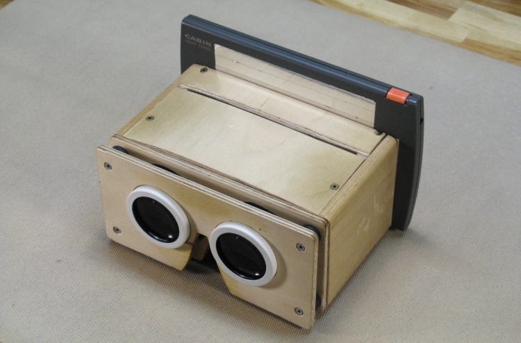
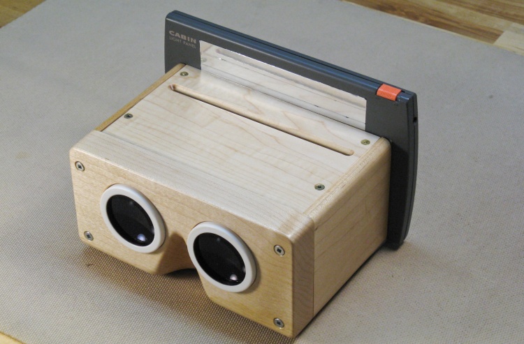
The original, with backlight in place
This photo shows the original viewer with the removable backlight in place. The cover has visibly warped upwards and the front sits on standoffs to achieve the correct lens-to-slide distance. It has also picked up grime from handling over the years.
My charge was to replace the cover, make a solid front and add a finish for more durability.
My charge was to replace the cover, make a solid front and add a finish for more durability.
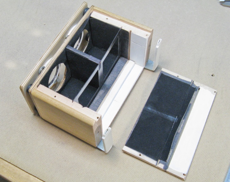
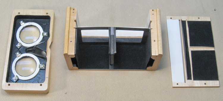
The inner bits
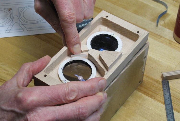
This shows the inside with the cover removed. There's not too much magic - just the lenses in front, a black eye separator down the center and a mask for the slide images, plus a slot for the slide.
The inside surfaces between lenses and slide have been painted black or have black flock paper to reduce reflections that could show up on the image. Surfaces behind the slide are painted white to help create a uniformly-lit image.
The inside surfaces between lenses and slide have been painted black or have black flock paper to reduce reflections that could show up on the image. Surfaces behind the slide are painted white to help create a uniformly-lit image.
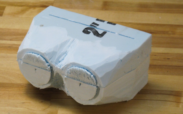
A finely-crafted 3D prototype of an alternate style
Those who know me might understand that it is difficult for me to make something square when it could be rounded instead.
So I crafted this fine curvey prototype from surplus Styrofoam SM to see what a rounder version of the viewer might look like. Isn't that sleek?
When I ran this past my friend, the word was still: square. Ah well - the customer's always right. But he did provide as a sop for my frustrated shaping genes a different square-ish viewer for me to work my curvey magic on when this one was done (yes, he has a few).
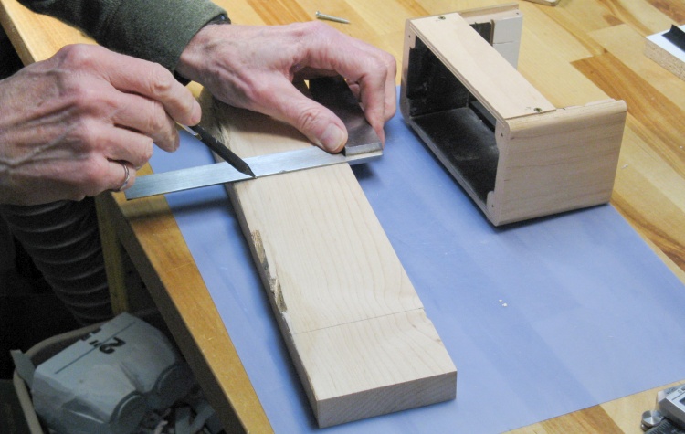
Marking a little maple plank for the front
The current viewer has maple sides and similarly-toned birch plywood so I went with maple for the new pieces.
I wanted to make the front from a single piece of wood and this plank was just about the right thickness. Here I'm marking off a section (in the middle of the board to avoid a knot) which will be used for the front.
I've already changed over the warped cover to a temporary replacement that correctly spaces the sides while I work on the front.
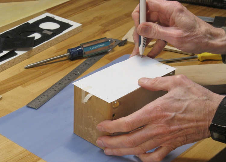
Making a paper pattern of holes
The original front assembly was held on with four screws and I intended to use the same screw holes for the new one. To transfer the hole positions, I made a pattern by taping on a rectangle of paper and punching holes as seen here.
Then the new front was set on top and the tape strips hanging out the sides were stretched up to tape the pattern to the new piece while the bottom tape strips were removed. That moved the pattern to the front piece and let me mark the hole positions.
Then the new front was set on top and the tape strips hanging out the sides were stretched up to tape the pattern to the new piece while the bottom tape strips were removed. That moved the pattern to the front piece and let me mark the hole positions.
Trimming the new front piece
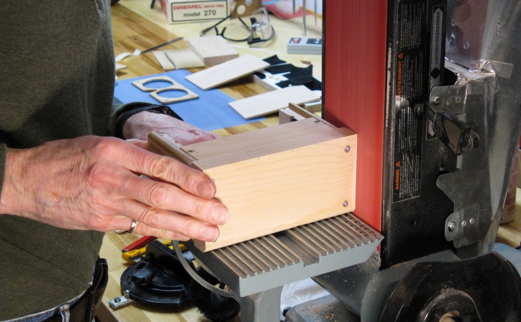
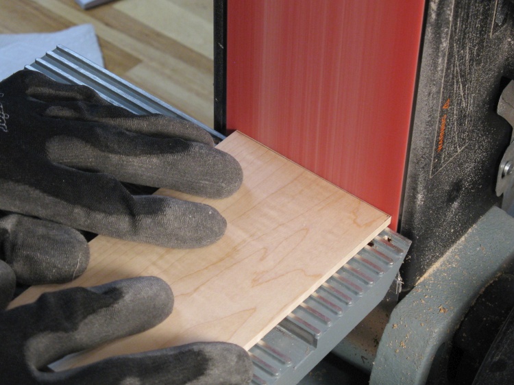
Once the mounting holes were drilled and countersunk, the front was screwed into place. I had made it slightly oversized so then the excess bits were sanded off until the edges of the front were flush with the original body.
Prior to fitting the front, I had flattened the front edges of the enclosure using the belt sander for a good fit. I simply don't see how anyone could live without a belt sander...
Prior to fitting the front, I had flattened the front edges of the enclosure using the belt sander for a good fit. I simply don't see how anyone could live without a belt sander...
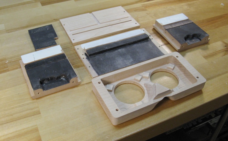
Drilling some not-quite-big-enough lens holes
The front piece needed its back side hollowed out to correctly position the flanges of the lenses. The hole diameter needed for the lenses was a non-standard size so initially I just drilled undersized holes so those sections wouldn't need to be milled out.
Clearing out the bulk of the wood from the back side
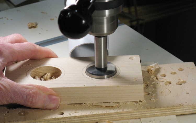
I started the hollowing by using a Forstner bit to remove the first half-inch or so of wood from the back side.
This type of bit works quickly for wood removal but leaves a pitted and grooved bottom surface.
This type of bit works quickly for wood removal but leaves a pitted and grooved bottom surface.
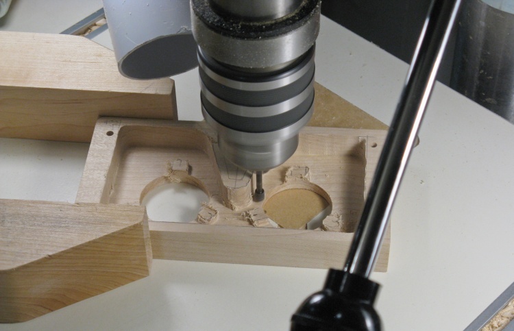
Milling the cavity with a small bit
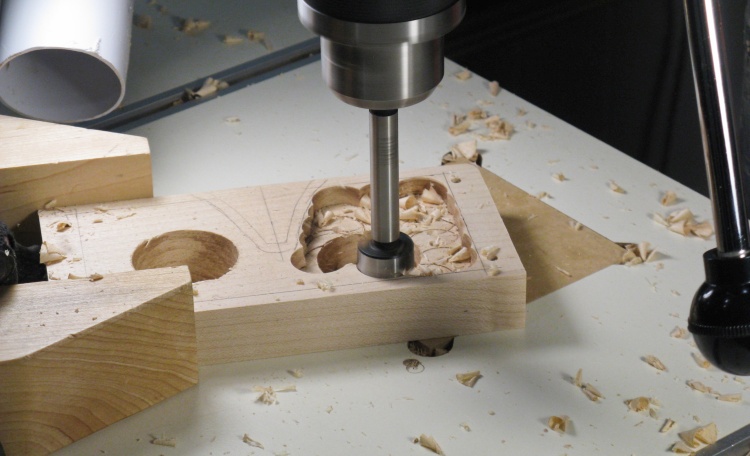
Then I switched to fluted bits which produce smoother surfaces but also work much slower.
I did the bulk of the work with a 1/2" bit and here I'm clearing some tight areas with a 1/4" bit.
The drill press has a rotary depth setting ring to limit how far down it will drill. But the opposite end of that ring can be used to hold the drill down to a specific depth as well. I used that feature to set the bit to cut about 0.03" from the wood surface and then the piece was moved around under the bit by hand using the big wooden clamp as a handle.
For drill-press milling in the past, I've also tried using router bits (which should cut faster) but the low drill speed combined with only two cutting flutes on the bits makes the setup very "grabby" and doesn't lead to very good results.
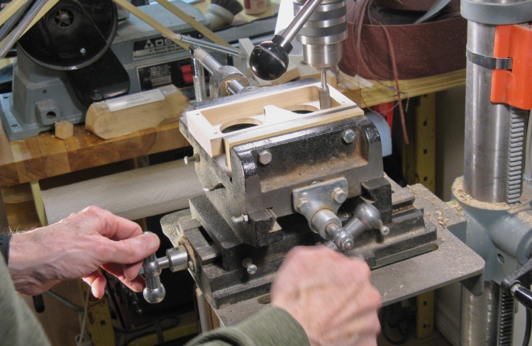
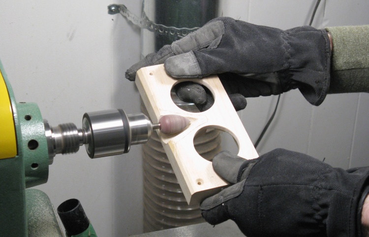
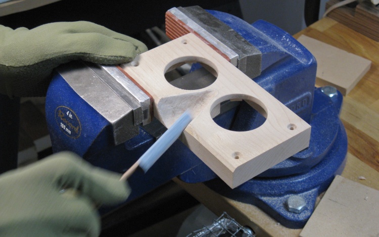
Milling the edges straight
The sides of the cavity were not very straight due to me just hand-guiding the wood under the cutter. To straighten them I put the wood in the cross-vice and recut the edges with the 1/2" bit.
The previous photo has some bosses milled into the wood to help hold the lenses in place but I mistakenly made them undersized. Oops. That wasn't fixable, so I milled them off and they're gone in this photo.
The previous photo has some bosses milled into the wood to help hold the lenses in place but I mistakenly made them undersized. Oops. That wasn't fixable, so I milled them off and they're gone in this photo.
Earlier I had drilled some undersized holes for the lenses. I could have sanded them larger but that's a bit of an imperfect process and I was aiming to get them nice and round. What they actually needed was 1-29/32"-diameter holes but I doubt they even make drill bits in that size (and that's 48.4mm so no help from the metric camp either). So instead of a drill bit, I'd need to substitute with a bit of complication. That involved making a 1-29/32" hole pattern on the lathe which I could then use to route the holes to the proper size;
Plywood blank for lens hole pattern taped onto wood disc
Cutting a hole to the correct diameter
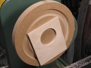
Pattern done
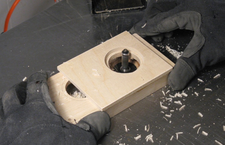
Routing lens holes to match pattern diameter
Then it was a fairly simple matter of taping the pattern to the front piece and using a flush-cutting bit on the router table to cut the maple front piece flush with the plywood pattern. Voilà - roundness in a weird size.
Rounding a lens-holding boss
As mentioned, I had messed up when trying to mill the bosses that help hold the lenses in place so instead I made separate bosses which I would add to the front piece.
Here I've cut out a little boss to an appropriate thickness and it's getting sanded with a curve to let it snuggle up to the lens.
Here I've cut out a little boss to an appropriate thickness and it's getting sanded with a curve to let it snuggle up to the lens.
Gluing in a boss
There were three bosses for each lens and in this photo I'm gluing one of them into place. The waxed paper prevents any glue squeeze-out from contacting the lens.
The bosses are not critical but they provide extra wood thickness to better support the lens-holding screws.
The bosses are not critical but they provide extra wood thickness to better support the lens-holding screws.
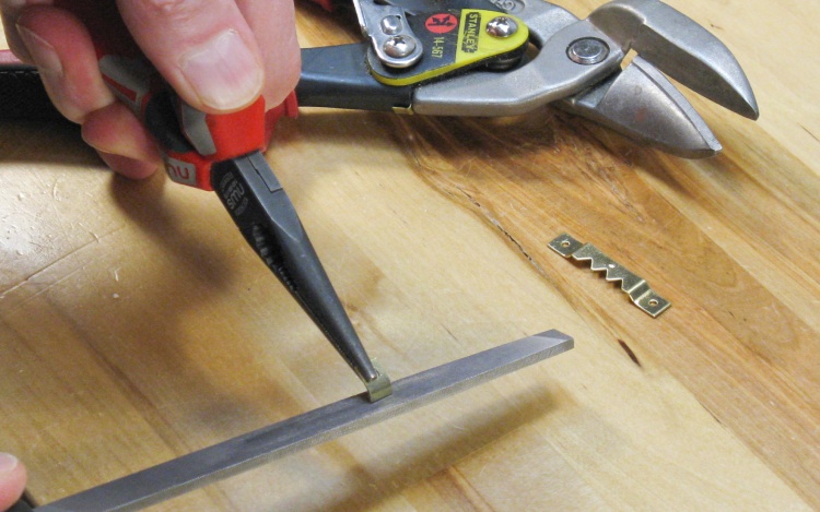
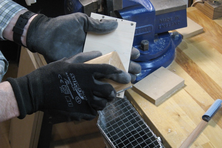
Making a lens-holding bracket
I made some small brackets (out of brass picture hangers) that would hold the lens flange using a screw. A bend in the bracket would let it apply pressure even if the boss was not the exact same height as the lens flange.
In this shot I'm filing the sharp edges off the cut side of one of the brackets.
In this shot I'm filing the sharp edges off the cut side of one of the brackets.
Making room for a nose
Then it was time to shape the nose cutout. I used a coarse carbide grinder mounted to the lathe to do the bulk of the shaping.
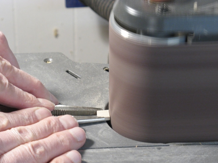
Smoothing off the grinding marks
And of course the cutout was sanded to remove the shaping marks, first with a small drum sander and then by hand as in this photo.
Except for a bit of corner rounding, that was pretty much it for the viewer front.
Next up was the cover;
Except for a bit of corner rounding, that was pretty much it for the viewer front.
Next up was the cover;
I decided to use solid maple for the new cover (as opposed to plywood) since the slot for the slide would look a bit better. The cover needed to be only 0.2" thick so I cut down a thicker board. I actually made two blanks in case I messed up the first one but in the end the first one worked out.
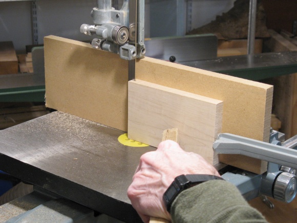
Cutting some maple for the cover
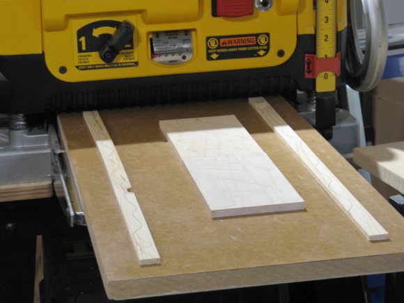
Two blanks for cover pieces heading into planer
Tweaking the size of the cover
The viewer wasn't perfectly square so I trimmed the cover to fit nicely using the belt sander.
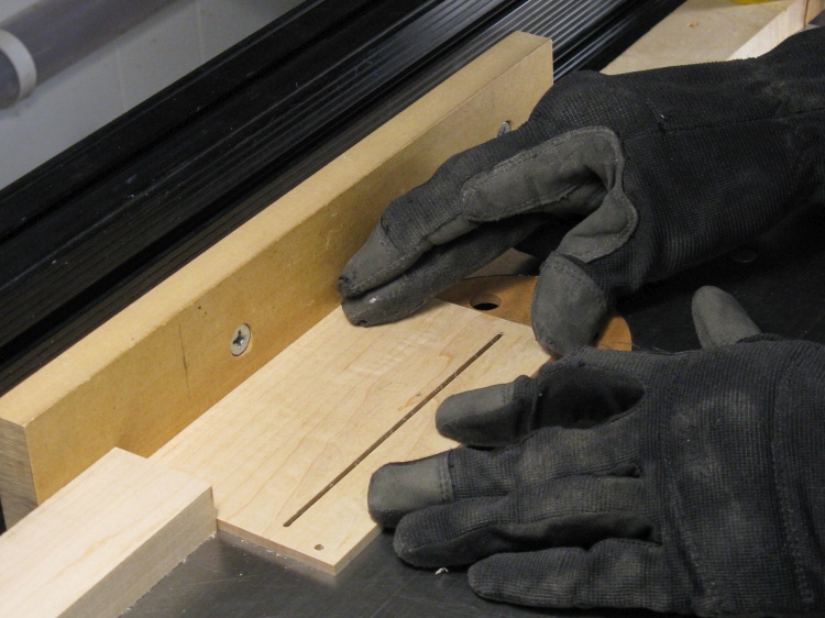
Routing the slot for slide insertion
The slot for the slide needed to be about 0.085" wide and I had a Dremel bit of the correct size, so that was mounted in the router to make the slot.
Like the original cover, the new version also got a bevel on the top side of the slot (the bottom of the wood in this photo) so that it would be easier to insert the slide.
Like the original cover, the new version also got a bevel on the top side of the slot (the bottom of the wood in this photo) so that it would be easier to insert the slide.
Extra routing to hold internal gubbins
The bottom side of the cover got a couple more details routed in as well, including shallow slots for the eye separator and the mask.
Cleaning up the original pieces
Then everything was sanded. In this shot I'm working on the bottom piece.
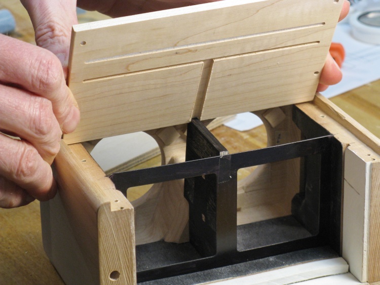
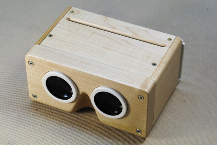
Assembled with shiny new pieces
This photo shows the assembled viewer with the new pieces in place, less the lenses.
...and then disassembled for finishing
But in order to apply the finish it all had to come apart again. This is the "exploded" view.
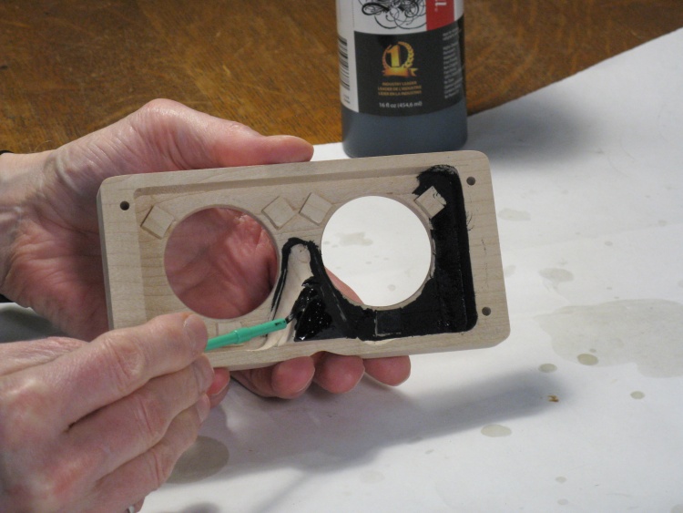
Blackening inside of front
The irregular back side of the front piece needed some darkening to prevent reflections so I painted on a coat of super-black India ink, my favorite "blackener". It's very black.
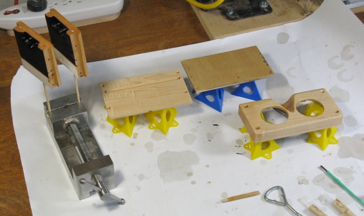
First coat of varnish on
Then it was just a matter of varnishing all surfaces of all the pieces. This is the aftermath of the first coating operation, using my favorite Polyurethane varnish.
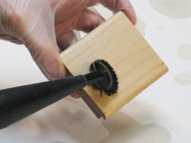
As usual, the varnish needs to be roughed up between the coats for good adhesion of the next coat. That involved rubbing with #0000 steel wool and then vacuuming and wiping off any steel wool residue;
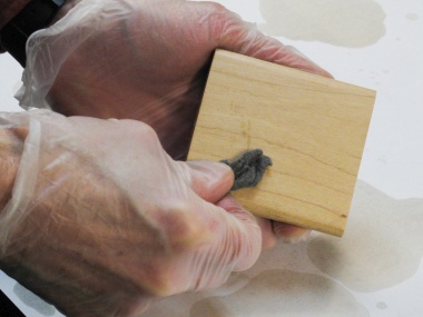
Roughing up with steel wool
Vacuuming off the resulting steel/varnish bits
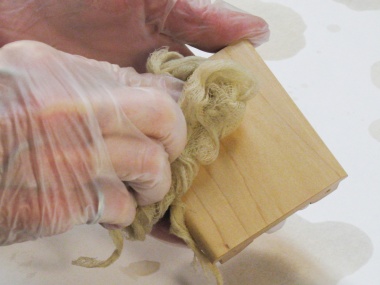
Picking up any missed particles with a tack cloth
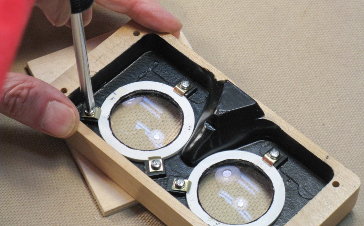
Installing the lenses
Once everything was varnished and allowed to dry for a couple days, it was time to start the re-assembly.
I began by installing the lenses. In this shot I'm adding the last lens-holding bracket screw.
I began by installing the lenses. In this shot I'm adding the last lens-holding bracket screw.
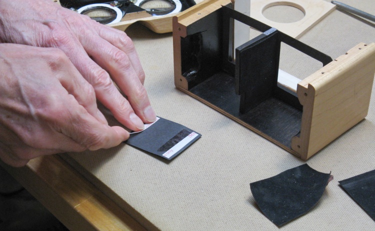
Sticking on some flocking paper
Most of the area between the lenses and slide had black flock paper on it. This paper is excellent at absorbing light and preventing reflections. I was able to reuse the original paper and just applied new tape as shown in this shot.
With some flattening, some vacuuming and some retaping it was good as new.
With some flattening, some vacuuming and some retaping it was good as new.
Everything ready to go together
The cover received flocking paper in the front and a coat of white exterior latex in the back. Then the viewer was ready to go together.
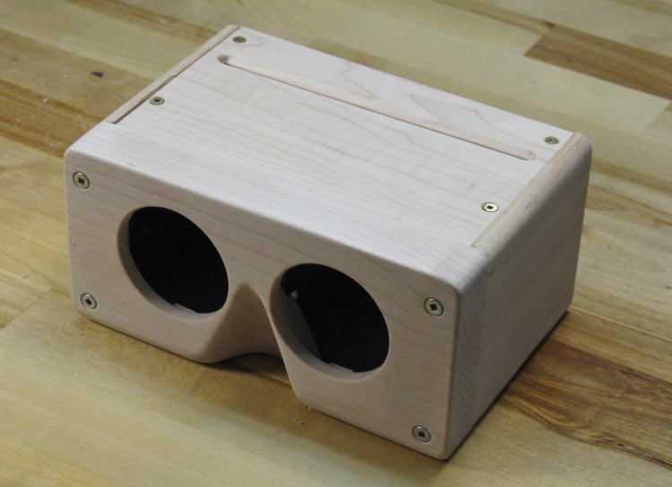
Everything together
A few screws later and it was done.
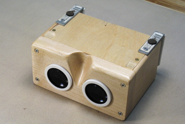
Backlight installed
View with the backlight installed.
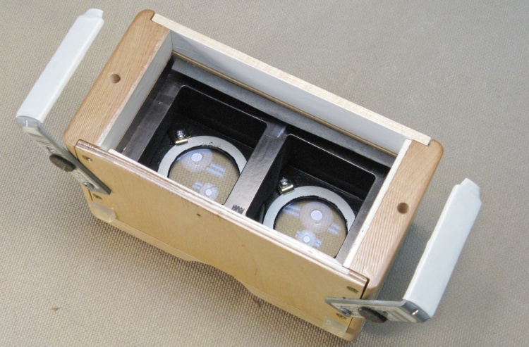
Looking into the back
The light's-eye view.
The brackets can be moved aside like this to use the viewer with an external light source (best is outdoors).
The brackets can be moved aside like this to use the viewer with an external light source (best is outdoors).
Bottom
And finally, a view of the bottom.


