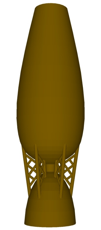
This vessel follows the geometry of the reinforced vessel that had inspired it which with some imagination, could be viewed as a (rather leaky) fuel tank interconnected with a rocket nozzle.
Maybe sorta vaguely rocket-like?
Of course that's a rather impractical arrangement in an actual rocket since you usually want the nozzle to be steerable. But hey - this piece of figured maple isn't blasting off any time soon. Rather than use fins on this one, I decided to use more-interesting girder structures. I had an image in my mind's eye of rocket fuel tanks interconnected with girders but I was unable to find any pictures that fit that particular pattern of neuron firings; however I carried that imagined girder concept over to replace the fins.

The plan, side view
The vessel, if it was made from milk chocolate
Body
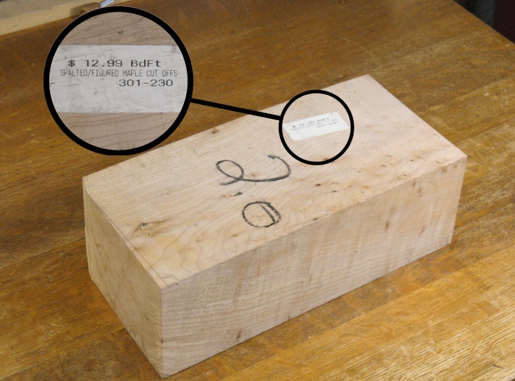
A nice block of Figured Maple
I happened to have a suitably-sized block of Figured Maple that I thought it would look nice in the tapered shape of this vessel (2.0 board-feet of it, in fact).
I had bought it back in whoknowswhen to use for whatever - you've gotta jump on these rare finds when you come across them.
I had bought it back in whoknowswhen to use for whatever - you've gotta jump on these rare finds when you come across them.
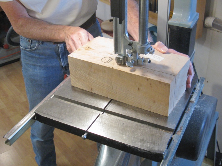
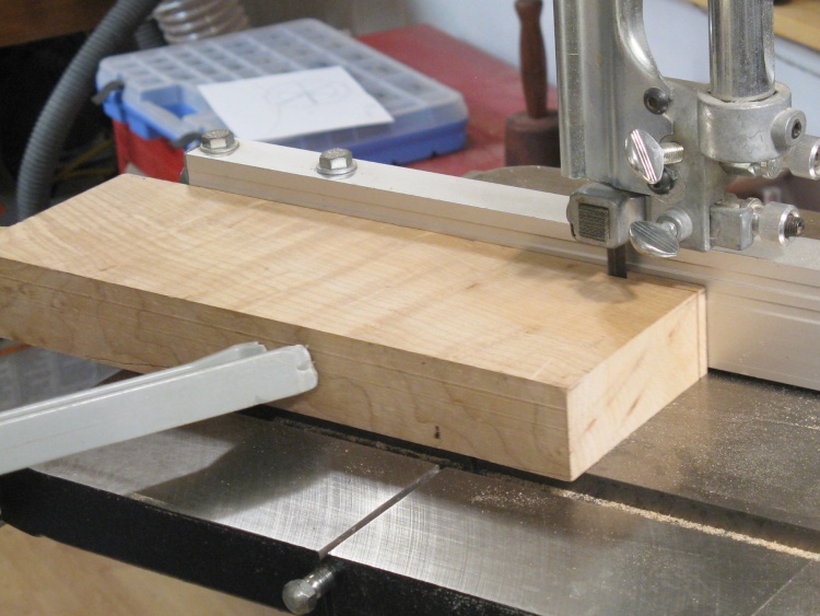
Cutting a square-sectioned blank
The block was wider than needed so I cut it down to 4 x 4" on the bandsaw.
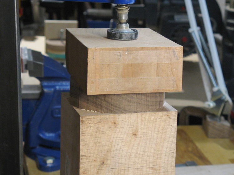
Gluing on a round end piece
The block was just barely longer than the finished size of the vessel, leaving no room for the faceplate-mounting screws.
To make space for them I glued a walnut disc onto one end. The square block on top in this photo is just to distribute clamp pressure.
To make space for them I glued a walnut disc onto one end. The square block on top in this photo is just to distribute clamp pressure.
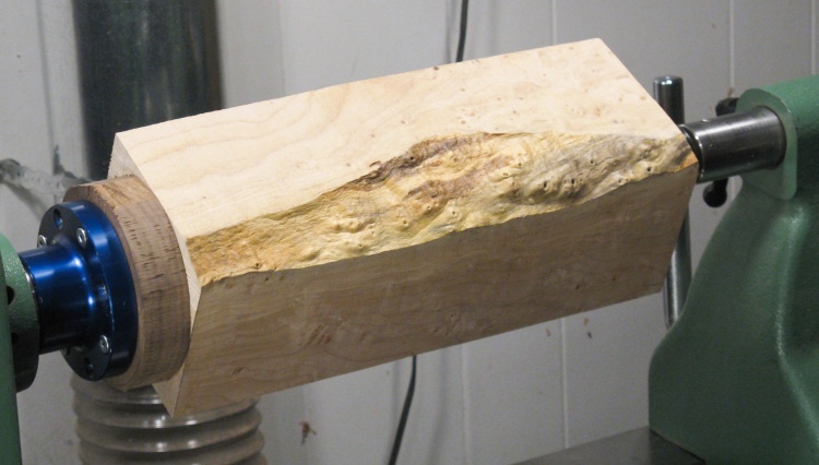
An interesting live edge that I plan to turn into shavings
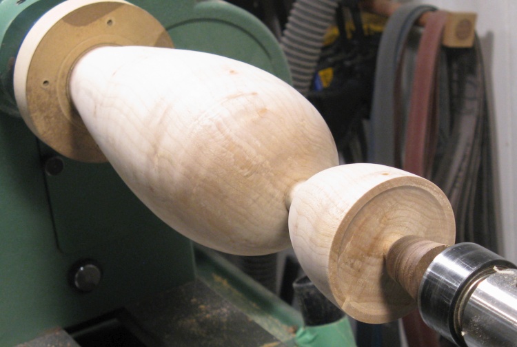
Here the blue faceplate has been screwed to the walnut disc and the whole assembly mounted to the lathe.
This block has a kind of nice-looking live edge which I'm sure will enhance the look of the big bin of shavings in the dust collection system.
This block has a kind of nice-looking live edge which I'm sure will enhance the look of the big bin of shavings in the dust collection system.
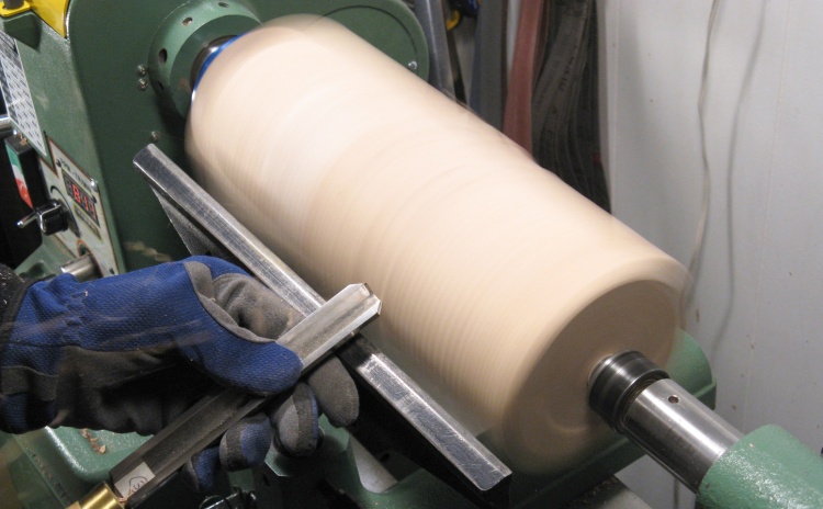
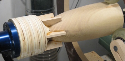
Starting the rounding
As usual, I used a roughing gouge to round the block into a cyllinder as shown in this photo, which is tragically lacking any flying shavings.
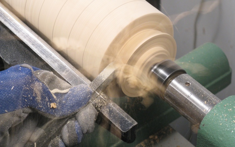
Starting to reduce the diameter with a big chisel
Once the block had reached a state of cyllinderness (cyllindricality?), I pencilled guide lines at one-inch intervals along the length and then started to cut the sections to the proper diameters as shown here.
Now, this shot has some decent flying shavings.
Now, this shot has some decent flying shavings.
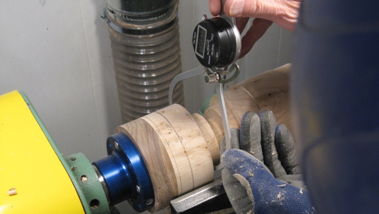
Checking a diameter
For each diameter, I "snuck up" on the size in multiple steps to make sure it didn't end up too small.
Here I'm measuring one of the diameters with a set of digital calipers before taking the next little bit off.
Here I'm measuring one of the diameters with a set of digital calipers before taking the next little bit off.
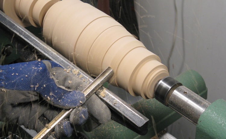
Starting to smooth out the surface
Once all the sections were the proper size, I removed the corners to tie the reference diameters together.
I started with this high-angle bowl gouge and switched to a scraper for final smoothing.
I started with this high-angle bowl gouge and switched to a scraper for final smoothing.
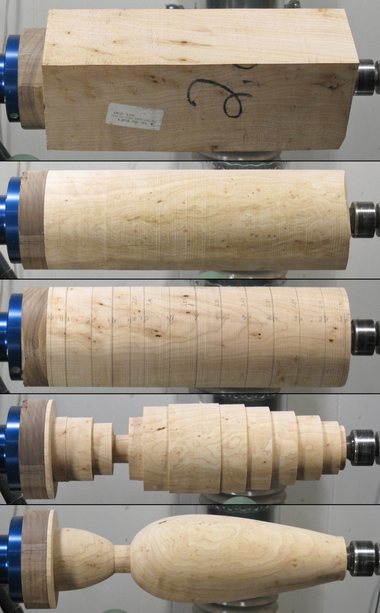
The turning summary photo
This composite shows the turning sequence with much less word pollution;
The blank
Rounded
Marked
Reference diameters cut
Shaped
The blank
Rounded
Marked
Reference diameters cut
Shaped
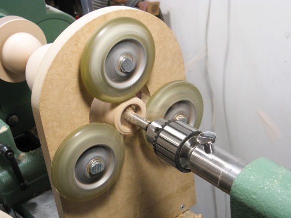
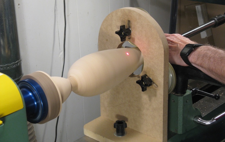
Then it was time to start the hollowing. I set up the steady rest and placed its wheels to run on that extra little bit at the top.
Hollowing is a slow process (especially near the center where the wood isn't moving very fast) so it helps to drill as large a hole as practical. I commenced the drilling operation with a 1-1/4" Forstner bit but that only went about 4" deep. I also use the hole as a guide to determine how deep to hollow the vessel so I switched to a smaller but longer bit and drilled in to where I wanted the bottom to be.
Hollowing is a slow process (especially near the center where the wood isn't moving very fast) so it helps to drill as large a hole as practical. I commenced the drilling operation with a 1-1/4" Forstner bit but that only went about 4" deep. I also use the hole as a guide to determine how deep to hollow the vessel so I switched to a smaller but longer bit and drilled in to where I wanted the bottom to be.
First a not-too-deep large hole
...and then an all-the-way-to-the-bottom smaller hole
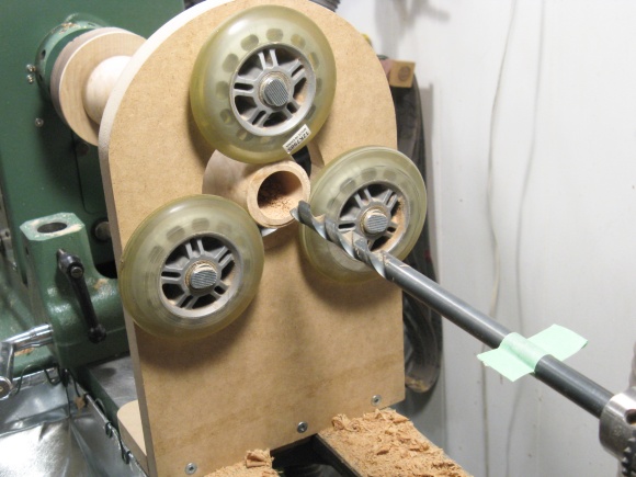
Starting in on the hollowing
I used my hollowing tool and in this shot I'm maybe a quarter of the way to the bottom based on the laser dot position.
Since the mouth of the vessel is so narrow, the cutting tool bar can't move much side-to-side and as a result it couldn't cut a very wide swath in the vessel. It took three or four angle settings of the cutter head to cover the full diameter. That requires pulling the tool out, loosening the locking screw, adjusting the cutter angle and retightening the screw. To make matters worse, the cutting depth is usually limited by the cutter geometry to less than an inch at a time so I needed to cycle through the cutter angles a dozen or more times too.
Once the bulk of thewhining hollowing was done, I switched to some wider cutters to smooth out the wall profile. The wall thickness ended up around 0.18".
Since the mouth of the vessel is so narrow, the cutting tool bar can't move much side-to-side and as a result it couldn't cut a very wide swath in the vessel. It took three or four angle settings of the cutter head to cover the full diameter. That requires pulling the tool out, loosening the locking screw, adjusting the cutter angle and retightening the screw. To make matters worse, the cutting depth is usually limited by the cutter geometry to less than an inch at a time so I needed to cycle through the cutter angles a dozen or more times too.
Once the bulk of the
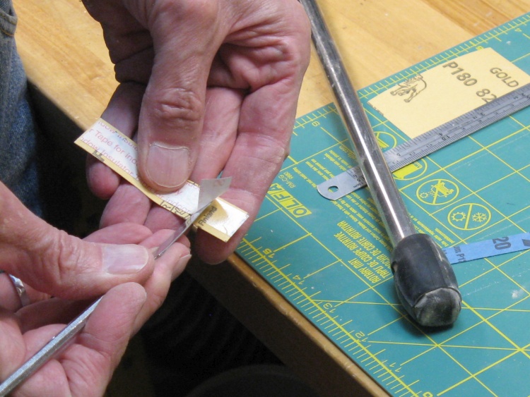
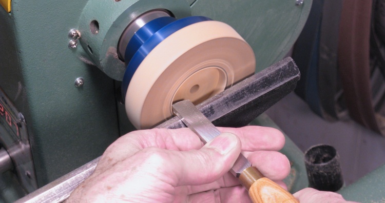
Prepping some sandpaper for inside sanding
When the inside was a smooth as I could practically get it with cutters, that signalled that it was time to switch over to sanding.
In this photo I'm removing some tape liner on a piece of sandpaper that will be stuck to the rounded sanding tool on the bench.
In this photo I'm removing some tape liner on a piece of sandpaper that will be stuck to the rounded sanding tool on the bench.
Sanding the inside
The inside was sanded to remove any remaining tool marks. I used this long-shafted tool which was modified years ago from a manual hollowing tool.
I started with 150 grit sandpaper and progressed to 400 and after lots of peering inside with a flashlight between bouts of sanding, the surface finally looked decent.
I started with 150 grit sandpaper and progressed to 400 and after lots of peering inside with a flashlight between bouts of sanding, the surface finally looked decent.
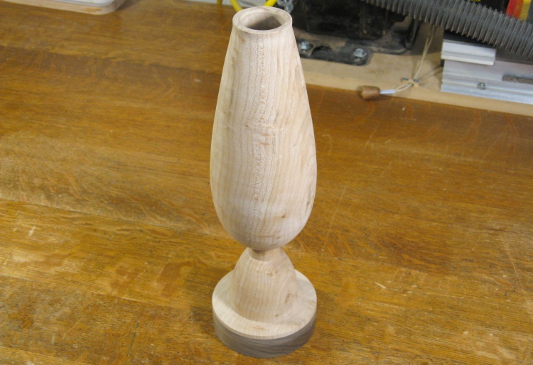
Done except for some extra top and bottom bits
Then it came off the lathe for a brief respite on the bench, but it will need to go back on to get the bottom finished off.
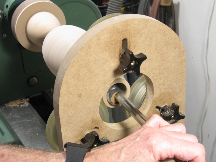
Making an MDF jam chuck for the top
The vessel needed to be flipped end-for-end on the lathe so to hold the top, I cut a circle into a piece of MDF on the faceplate. This formed a jam chuck into which the top of the vessel would fit tightly. That allowed the lathe to spin the vessel without damaging the top.
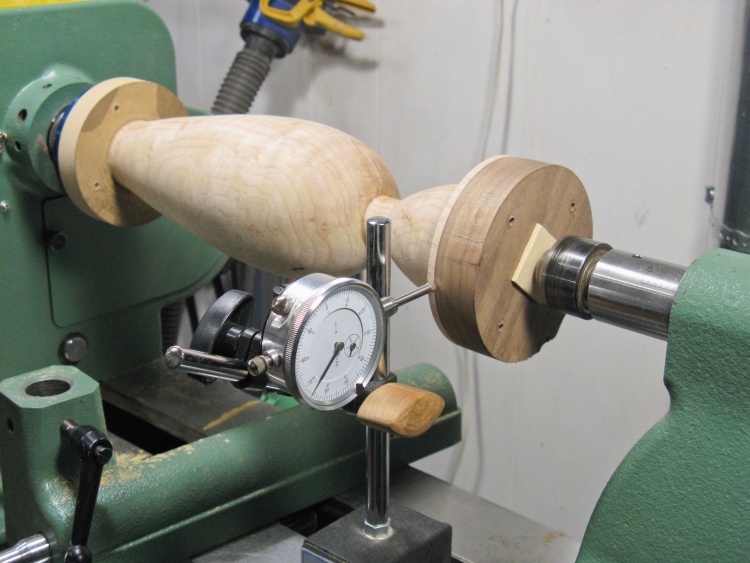
Finding the center on the bottom
I was going to need to reduce the diameter of the neck portion so the vessel needed to be well-centered. The top would be OK but unfortunately there was no good center mark on the bottom so that needed to be located accurately. Eyeballing it doesn't work and even measuring isn't accurate enough.
I used the following technique to do the centering:
- The point of the tailstick live center is stuck into a thin piece of softwood I'll call the "wafer" (the light-colored square on the bottom in this shot).
- The wafer is initially centered by eye and then the live center is tightened down enough to provide adequate friction between the wafer and the vessel. The point must not come out the other side of the wafer.
- Next the dial indicator is set up and the vessel is rotated by hand so that the eccentricity can be determined from the dial readings (highest minus lowest values).
- The vessel is rotated so the dial reads the lowest value (vessel furthest away) and the base of the vessel is tapped toward the indicator with a small hammer. This slides the vessel across the wafer and should reduce the eccentricity.
- This measure/tap process is repeated until things are centered well enough.
Then when centering is as good as it will get, the tailstock is extended further to drive the live center point through the wafer and into the bottom of the vessel to mark the center. Then I loosened the tailstock, discarded the wafer and tightened it back up with the live center in the newly-marked hole. I was able to get to within about 0.006" with this technique which is close enough to be able to sand out any artifacts caused by re-turning the slightly eccentric vessel.
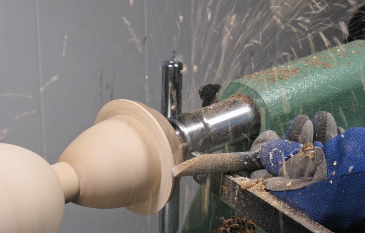
Getting rid of that extra bottom wood
Then it was on to cutting off the extra wood at the bottom.
I had also intentionally left the thin neck of the vessel thicker than the finished size so it would be stronger for the hollowing process, and after this shot was taken that was turned down to the finished size as well.
I had also intentionally left the thin neck of the vessel thicker than the finished size so it would be stronger for the hollowing process, and after this shot was taken that was turned down to the finished size as well.
Bottom done
Here the extra bottom wood has been removed, the neck area thinned and reshaped and a foot cut into the bottom.
After this shot, the vessel came off the lathe for good. The last little nub of wood on the bottom was cut off and the bottom was smoothed out.
After this shot, the vessel came off the lathe for good. The last little nub of wood on the bottom was cut off and the bottom was smoothed out.
Girders
Sketching the profile
Next up: girder fabrication. But first:
I wanted a pattern for the girders so I needed an accurate profile of the turned vessel. To do that I projected a focussed beam from an LED flashlight past the side and traced the shadow onto a 1/8"-thick piece of plywood using a pencil.
I wanted a pattern for the girders so I needed an accurate profile of the turned vessel. To do that I projected a focussed beam from an LED flashlight past the side and traced the shadow onto a 1/8"-thick piece of plywood using a pencil.
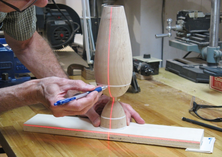
Marking girder locations
I also marked the girder top and bottom locations onto some thin tape strips, using the laser level to ensure they were vertical.
To make the pattern I cut out the proper width on the marked plywood and then cut the ends a bit long. Those ends were incrementally trimmed using the spindle sander while checking the fit between adjustments.
Shaping girder pattern
Checking pattern fit
Cutting a couple slices for the girders
Then for the actual girders;
I went back to the piece cut off the original blank and cut a couple of thin strips to be used for the girders.
I went back to the piece cut off the original blank and cut a couple of thin strips to be used for the girders.
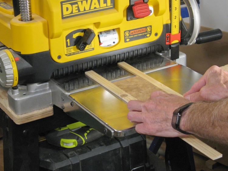
Thickness planing the girders
Those strips were cut a bit thick and in this shot I'm putting them through the thickness planer to bring them down the size I'll need (0.16" thick).
The long pieces flanking the figured maple are to prevent snipe.
The long pieces flanking the figured maple are to prevent snipe.
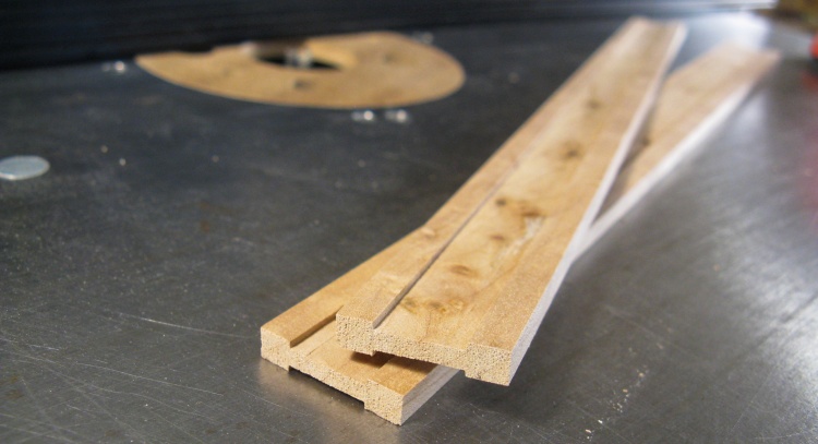
Girder profiles after routing the centers thinner
After planing, the strips were cut to width and then the centers routed down to about 0.1".
This big photo matrix shows the "processing" the solid girder blanks went through on the way to their final shape.
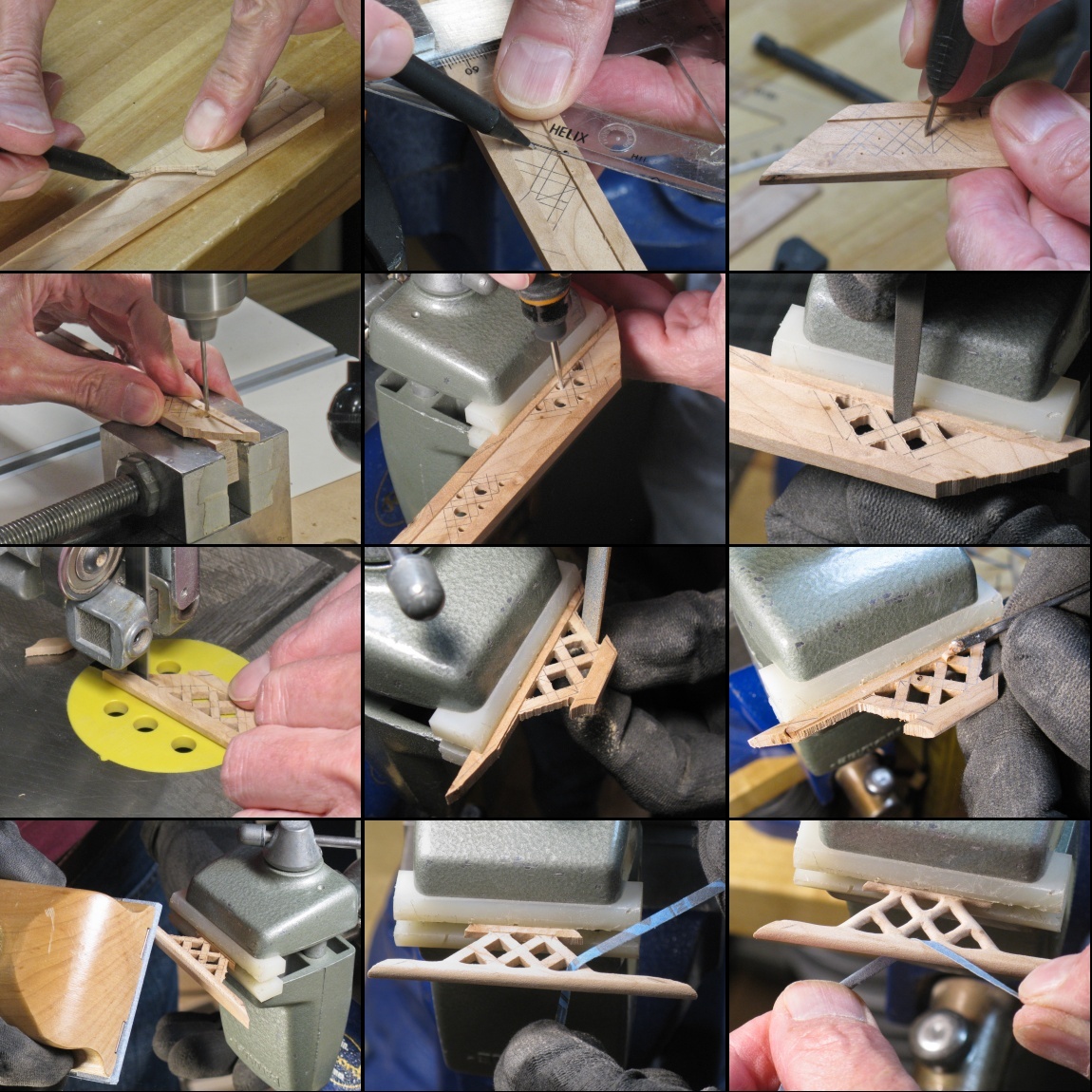
A big matrix of girder-forming photos
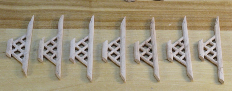
Girders all shaped (plus a spare)
One girder had a tiny knot which messed up one end so I glued in a patch (the ugly one on the right). But in case that wasn't good enough, I also made a spare girder.
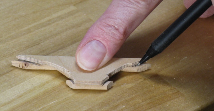
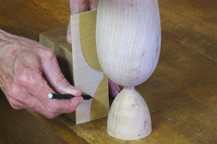
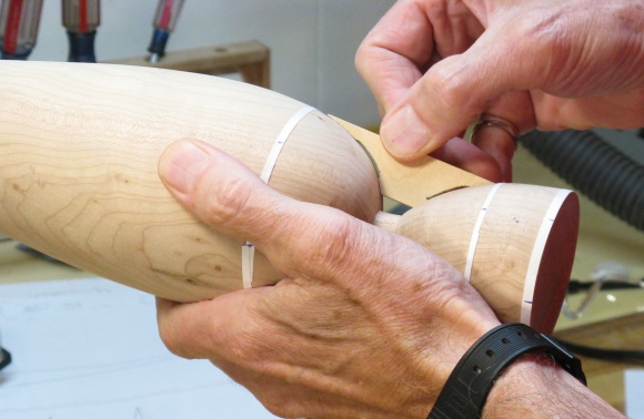
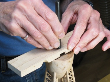
Marking the leg lengths
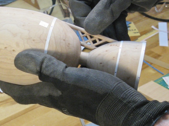
The girders were fabricated with legs longer than needed so I could individually trim them to length. Here I'm marking the default length using the plywood pattern made a while ago.
Then the legs were fitted to the body; I used the spindle sander to adjust the ends bit by bit until all four girder ends were as close to flush with the surface as possible.
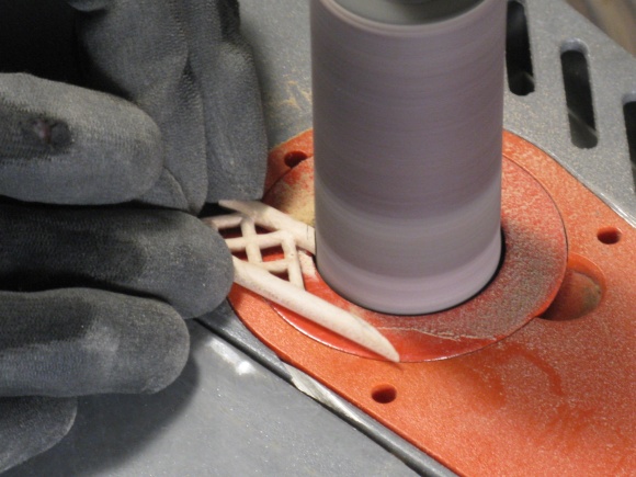
Adjusting leg lengths
Checking the fit
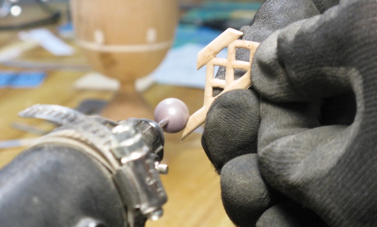
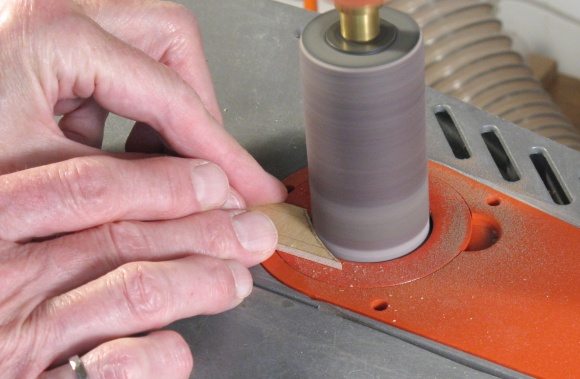
Hollowing the flat faces
To enhance the fit, I hollowed the girder ends using an abrasive sphere so they would conform a bit better to the curved surface.
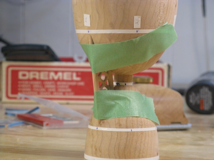
Gluing on the first girder
The girders were glued on one at a time using masking tape to hold them in place while they dried.
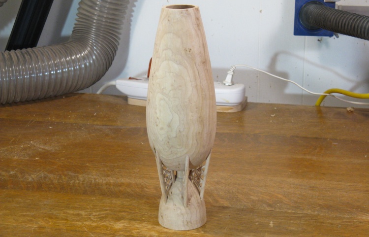
All the girders are on
This shot shows the vessel with all six girders in place.
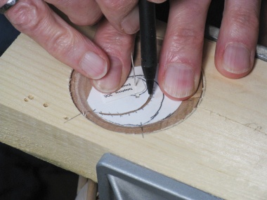
The only remaining woodworking was to add the initial circle to the bottom. I had decided to place it in the center of a inscribed pattern so I took some care finding the center and properly aligning the circle pattern used to guide the Dremel cutter.

Finding the center
Centering the pattern
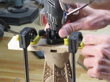
Cutting initial circle
Holding round vessels for carving without marring the finished surface is always a challenge. For this one I decided to make a circular softwood clamp to hold the very bottom. I started with a trimmed 2x4.
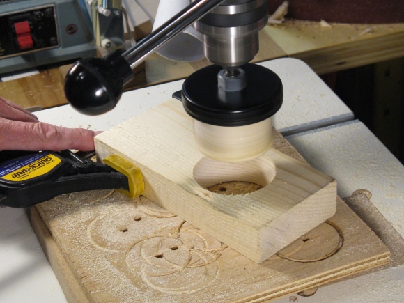
2-1/2" hole for vessel bottom
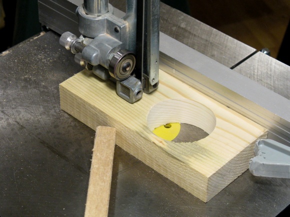
Adding relief cut
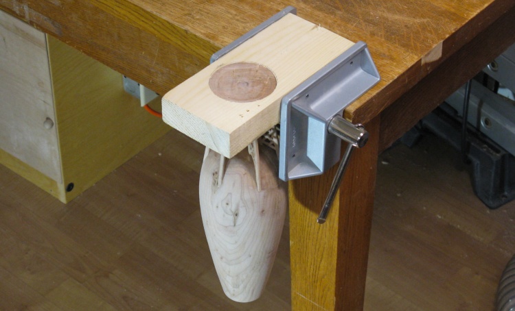
Vessel clamped to access bottom
The clamp worked pretty well. Tightening the vise closed the relief cut in the wood, which held the bottom tightly.
I set it up on my low table so it would be at a convenient height for carving.
I set it up on my low table so it would be at a convenient height for carving.
I had made a cardboard pattern that pivoted on a taped-in center pin and used that to draw curves at six evenly-spaced angles around the bottom. The curves were carved first and then I proceeded to the straight lines after first making a little aluminum square to use as a straightedge. All the carving was done with my tiniest V-tool.
Marking bottom pattern
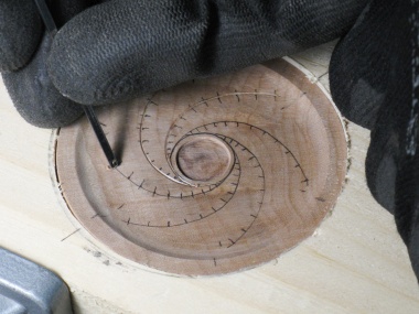
Carving curves
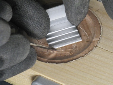
Carving straights

The completed bottom
The completed bottom.

Woodworking done
And that was it for the woodworking.
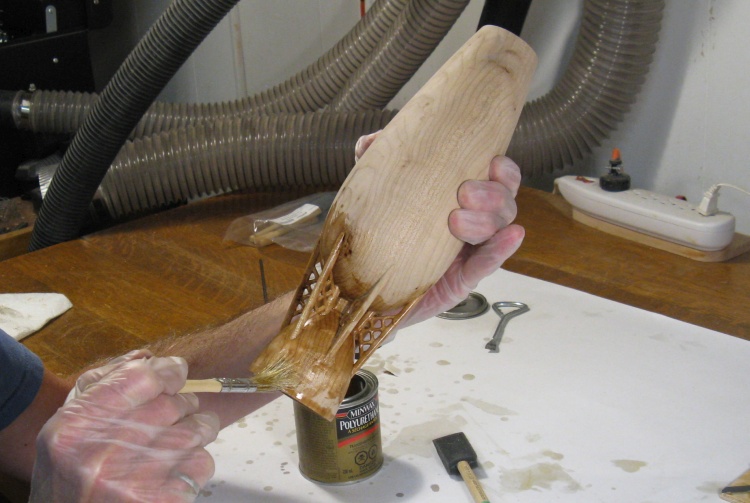
Adding the first coat of varnish
I used my standard MiniWax varnish, applied with a bristle brush to get the detail parts of the girders and a foam brush for the smoother bits.
First coat of varnish on
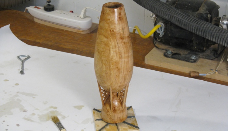
It darkened up nicely with the varnish. I went on to apply three coats.
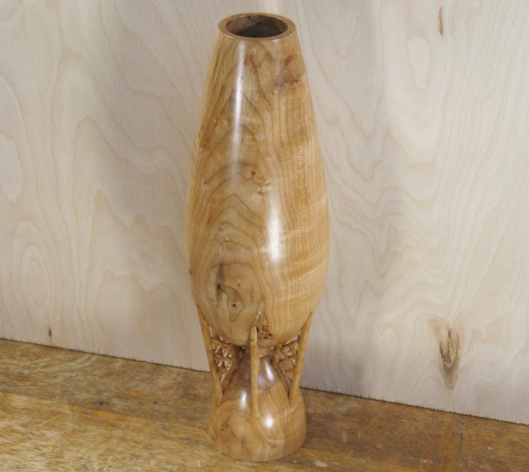
Done
Complete.


