I was pleased by how a previous laminated piece had turned out and decided that I should try a larger vessel. Like the first one, this design is inspired by the work of woodturner Virginia Dotson. I played around with the lamination pattern and settled on one giving a regular transition from light to dark. The construction was quite straightforward in concept; cut some boards to the right thickness, glue them together and turn a vessel. Of course it was a bit more involved but that pretty much covers the process.
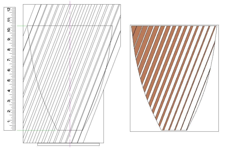
Plan showing side view of laminations
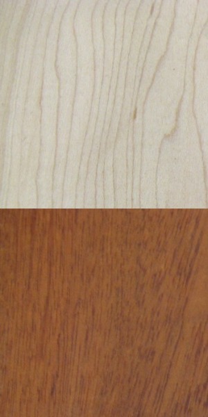
Yer contrast
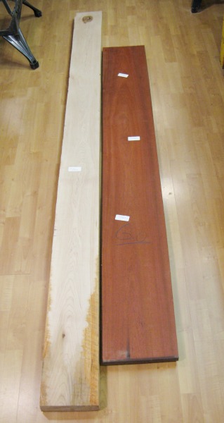
Starting planks
I started by browsing through the local Windsor Plywood for pairs of contrasting woods. I was looking for the classic light-and-dark and wanted fairly subtle grain since most of the feature of the vessel was in the color contrast.
I ended up selecting Maple as the light wood and Bloodwood as the dark. I hadn't used Bloodwood before, but it was a rich red color and was very dense and as a result, surprisingly heavy.
I ended up selecting Maple as the light wood and Bloodwood as the dark. I hadn't used Bloodwood before, but it was a rich red color and was very dense and as a result, surprisingly heavy.
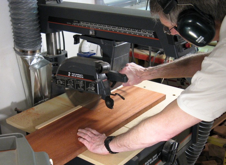
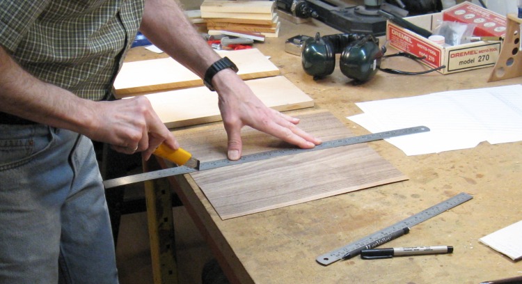
Cutting Bloodwood to length
I started by cutting a 14" length from each plank. This gave an inch or two extra on both ends of the vessel which was enough to allow for imperfect laminating.
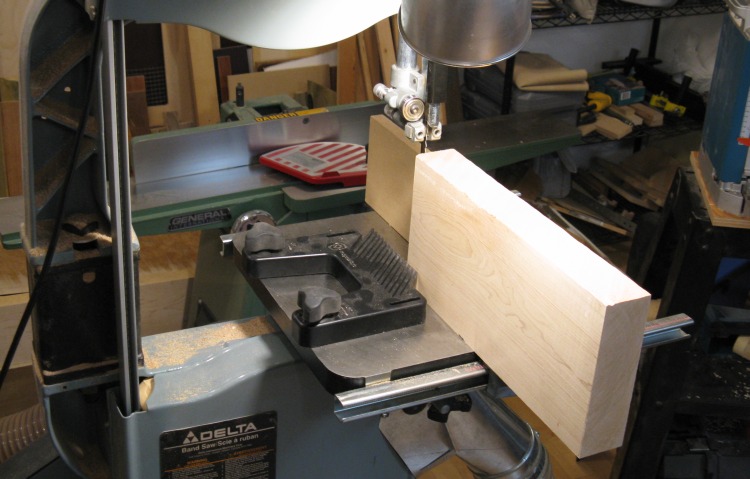
Ready to resaw Maple
There are 34 layers of wood forming the vessel, varying in thickness from 0.03" to 0.51" thick.
Here the bandsaw is set up for one of the first lengthwise ("resaw") cuts of the Maple to make one of those layers. The saw has been equipped with a new three-teeth-per-inch blade to cut through the 9" or so of wood.
Here the bandsaw is set up for one of the first lengthwise ("resaw") cuts of the Maple to make one of those layers. The saw has been equipped with a new three-teeth-per-inch blade to cut through the 9" or so of wood.
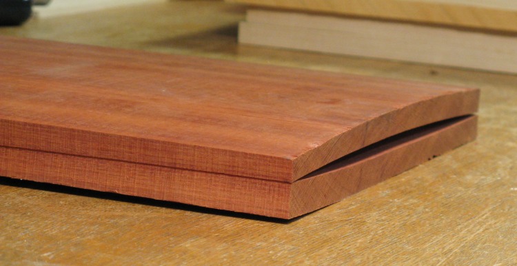
Holy warpage, Batman!
Cutting the maple went OK, but on the first resaw cut on the Bloodwood, there was a Bang! just as the cut finished and the two pieces popped apart in the center. There must have been a huge amount of internal stress in the plank that was released when it was cut.
It wasn't practical to further thin the pieces or even smooth the surface in their curved state and I knew of no good way to get rid of the warp. The pieces even started to crack when I tried to flatten them. After a great deal of thought I decided to leave the Bloodwood for another project where the planks could be used whole.
So then it was back to thedrawing board wood store.
It wasn't practical to further thin the pieces or even smooth the surface in their curved state and I knew of no good way to get rid of the warp. The pieces even started to crack when I tried to flatten them. After a great deal of thought I decided to leave the Bloodwood for another project where the planks could be used whole.
So then it was back to the
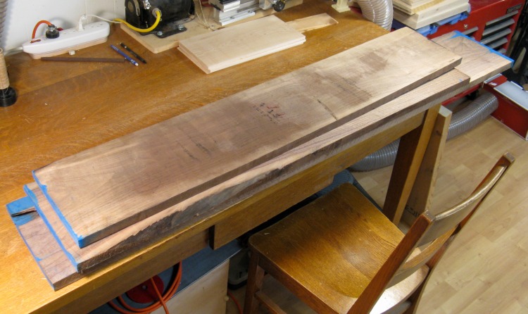
Version 2: Walnut
So being a bit more wary of potential problem woods, I opted for the somewhat safer Walnut, which as a bonus in woodworking is the classic pairing with Maple (and in ice cream sundaes too).
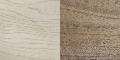
Yer new contrast
Robin isn't too impressed with the Walnut, either
Not that the "safe" Walnut was without a bit of internal stress either. I had variable levels of warpage with the worst being almost as bad as the Bloodwood.
I tried without much anticipation of success to unwarp one piece by soaking it in warm water and bending it back a bit to let it dry as shown here. Sure enough; no success.
Ultimately I was able to use some warped pieces by gluing to the growing stack of laminations and then smoothing the surface, but a number of pieces went unused.
Cutting Walnut veneer
Any imperfections in cutting or smoothing were more obvious on the thinner layers. So for the very thinnest I ended up using veneer.
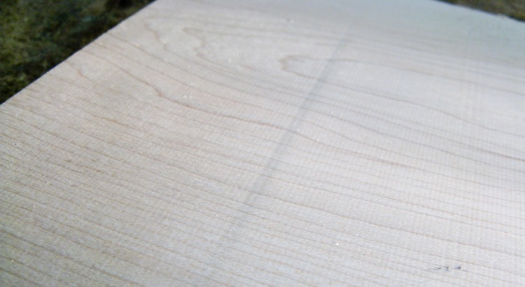
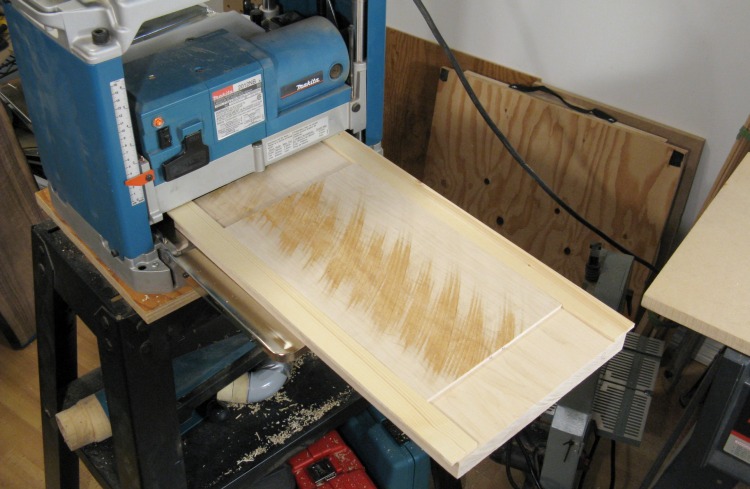
Snipe!
The surface left by the bandsaw is pretty rough and needs to be smoothed and flattened. The standard way to do that is to use a planer. Unfortunately small planers tend to have some level of "snipe" where they cut the ends of the boards slightly thinner than the middle. This happens for about two inches in from the leading and trailing edges. The thickness difference can be only 2 to 5 mil (thousandths of an inch) but this is easily felt and would certainly be visible on a glue joint between two pieces of laminated wood. In this photo the darker line across the board shows where the snipe starts.
One way around the snipe is to make the wood another four inches longer than you need and just cut off the sniped ends. However that seems like a huge waste of wood. And if I ever do this again, be assured that I will waste the wood.
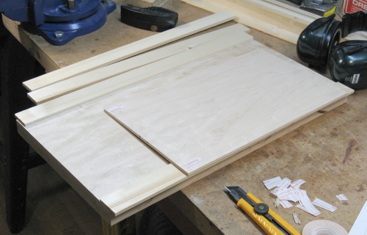
Anti-snipe sled
However since I had a number of pieces already cut to length, I opted for Plan B. That calls for adding flanking "rail" pieces of sacrificial wood that extend the extra length. They get planed with the desired wood and usually protect it from snipe. Unfortunately, it's a bit involved since you need to start with the rail wood the same thickness as the good wood and of course there were many thicknesses to do on this project. I used some softwood (old fence boards) for the rails.
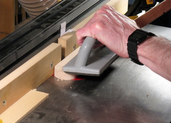
I ended up making a thick "sled" on which to place the working piece and the flanking rail pieces, all held down so they would remain in place through the planer. Here a piece of Maple is having tape applied to hold it to the sled.
I ended up making a thick "sled" on which to place the working piece and the flanking rail pieces, all held down so they would remain in place through the planer. Here a piece of Maple is having tape applied to hold it to the sled.
Sled going through planer
The sled isn't completely necessary, except without it, the three pieces of wood need to be arranged side-by-side with the proper offset and simultaneously slid into planer, which sometimes doesn't pulled them all through evenly. The sled gave them a surface to be affixed to and it resulted in more consistent planing.
With this somewhat involved setup I wanted to keep the amount of wood planed off each pass fairly low so it took 5 to 10 passes through the planer for each board to achieve the target thickness and smooth both sides.
This photo shows the good piece of wood between the two rails on the sled. The good piece still has the saw marks from the sawmill one one side and this process will plane them off and produce a clean surface.
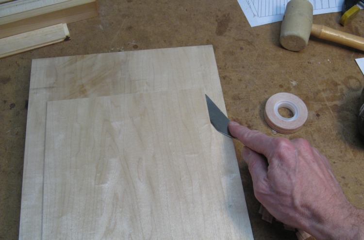
Removing the wood from the sled
After one side was planed smooth, the board was flipped and the second side was planed until the desired thickness was reached. Fortunately, the second side can use the same rails.
This is the same piece of wood as in the above picture, but with the surface planed smooth. This was the second side so the rails have already been taken off the sled and the piece is just being removed. I used the thin spatula to release the tape.
This is the same piece of wood as in the above picture, but with the surface planed smooth. This was the second side so the rails have already been taken off the sled and the piece is just being removed. I used the thin spatula to release the tape.
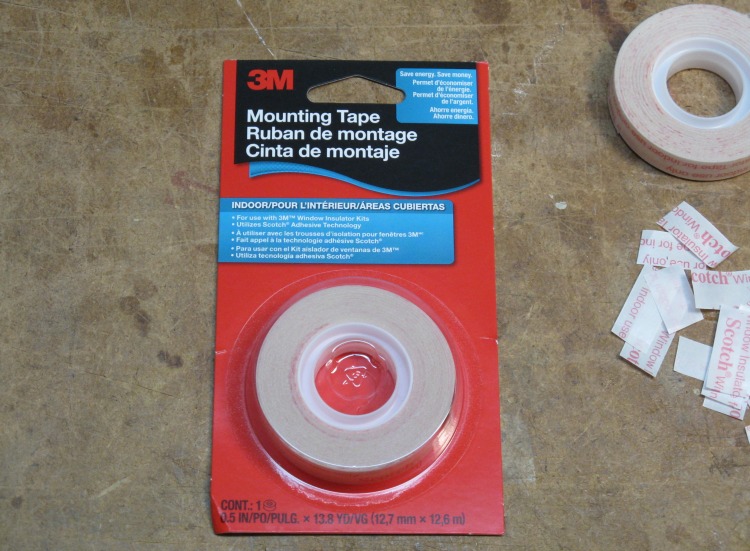
The proper tape
I'll do a little aside here and talk about the tape. This is window insulator tape - the thin transparent tape used to mount window insulating film if you have imperfectly sealed/insulated windows here 38° South of the North Pole. But this isn't just any tape. This is Minnesota Mining and Manufacturing (AKA 3M) Scotch brand tape. Remember that.
I ran out of this tape a couple years ago and bought a different brand. But it was horrible - it wouldn't peel off in one piece and the adhesive stayed behind in a gooey mess. It happened again when I ran out this year - the store didn't have 3M so I thought I'd gamble that another brand might be as good. Lost. After firing those into the waste bin with more force than was perhaps absolutely necessary, I ended up searching on-line to see who carried the "good stuff" (Walmart, as it turned out). I bought a few rolls and my blood pressure went down 23 points.
I ran out of this tape a couple years ago and bought a different brand. But it was horrible - it wouldn't peel off in one piece and the adhesive stayed behind in a gooey mess. It happened again when I ran out this year - the store didn't have 3M so I thought I'd gamble that another brand might be as good. Lost. After firing those into the waste bin with more force than was perhaps absolutely necessary, I ended up searching on-line to see who carried the "good stuff" (Walmart, as it turned out). I bought a few rolls and my blood pressure went down 23 points.
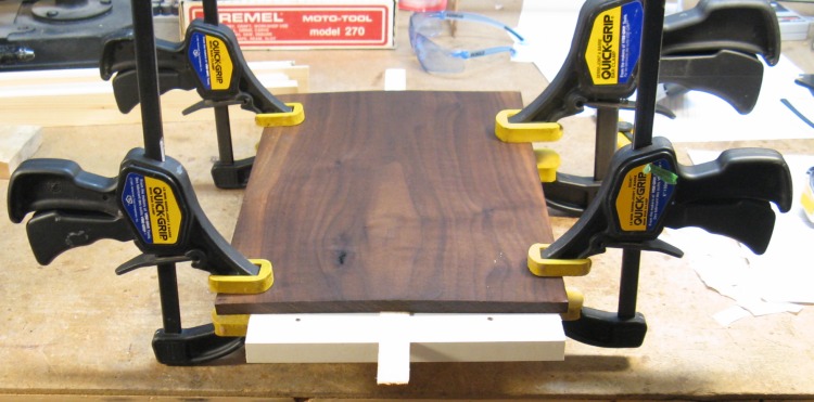
Adding some layers to lamination stackup
I started laminating pieces from either end, adding three or four pieces at a go. Here is the mostly-Maple end getting a few more layers glued on.
I used standard carpenter's glue spread with a putty knife. It took pretty much all of a 400 ml bottle of glue to do all the laminations.
I used standard carpenter's glue spread with a putty knife. It took pretty much all of a 400 ml bottle of glue to do all the laminations.
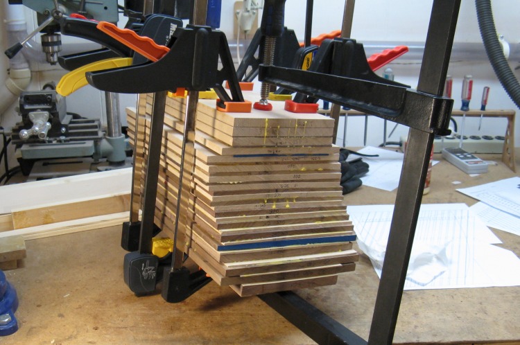
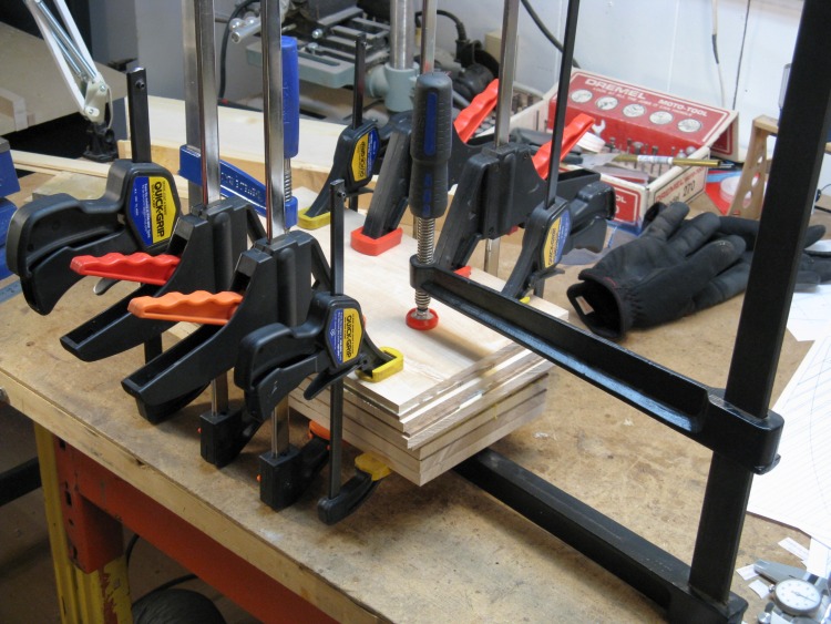
The final glue-up
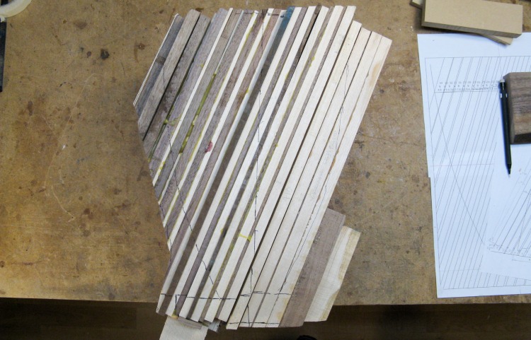
This is the final assembly stage where the stacks started from each end were glued together.
The composite stack is taller than it is wide, but that extra tallness will be needed because the vessel centerline is at an angle to the laminations as the next photo shows.
The composite stack is taller than it is wide, but that extra tallness will be needed because the vessel centerline is at an angle to the laminations as the next photo shows.
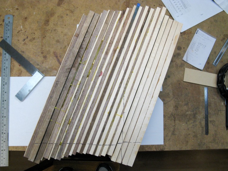
Reference lines added
The next order of business was to draw in the centerline and the baseline as can (barely) be seen here.
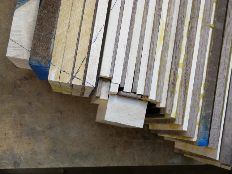
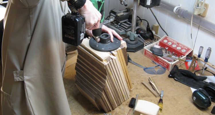
Extra wood for faceplate mounting added
I planned to use a 6-inch diameter faceplate which needed to mount parallel with the baseline and on the centerline. To accommodate that I needed to add a few pieces of wood to increase the width (the two on the left) and fill some gaps on the lamination ends (the irregular collection of scraps in the center of the photo).
Those would all be cut down even with the baseline using the lathe.
Those would all be cut down even with the baseline using the lathe.
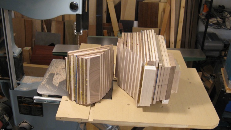
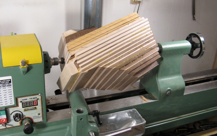
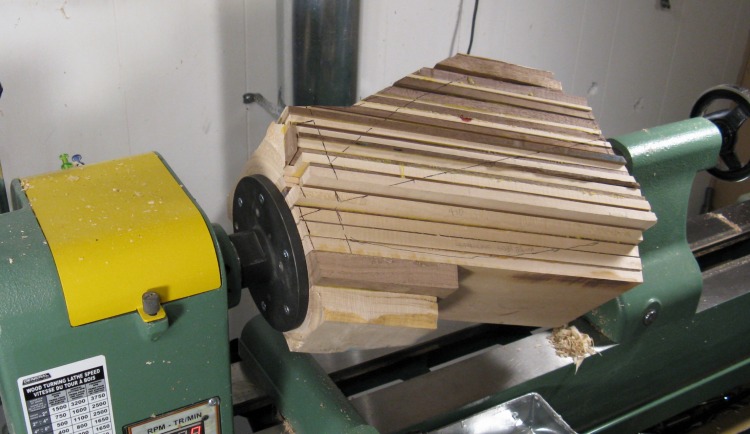
Chopping off a corner for balance
To spin this on the lathe, it was going to need to be reasonably balanced around the centerline. But a look at the "Reference lines added" photo above makes it obvious that it wouldn't be even close to balanced.
I took a guess and chopped off a big corner on the bandsaw as shown here. That turned out pretty good for a shot in the dark since the wood was close to being balanced when I got it on the lathe.
I took a guess and chopped off a big corner on the bandsaw as shown here. That turned out pretty good for a shot in the dark since the wood was close to being balanced when I got it on the lathe.
Embedding live center
Step 1 for turning was to adjust the balance of the wood and flatten one end for the faceplate. Here I'm embedding the tines of the live center into the proper spot on the wood so it has a good grip.
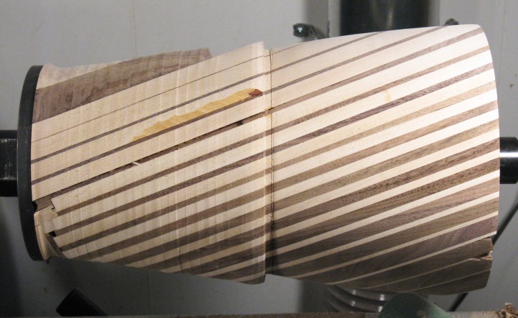
Almost-visible vessel outline (squinting helps)
Here is a shot with an ink outline of the vessel silhouette drawn on the wood. I wanted to confirm that everything looked correct before going any further.
Stack mounted and ready to flatten one end
The lamination stack has been mounted between centers on the lathe. As mentioned, the balance was pretty good so I was able to start without further adjustments and cut the left end flat to accept the faceplate.
Adding faceplate
After the one end was flattened, I pulled the wood off the lathe and mounted the faceplate. I used six #10 x 1 1/4" screws to hold things together.
Back on the lathe and ready to turn
Then it was back onto the lathe. I kept the tailstock with live center in place to provide a bit more support for the wood.
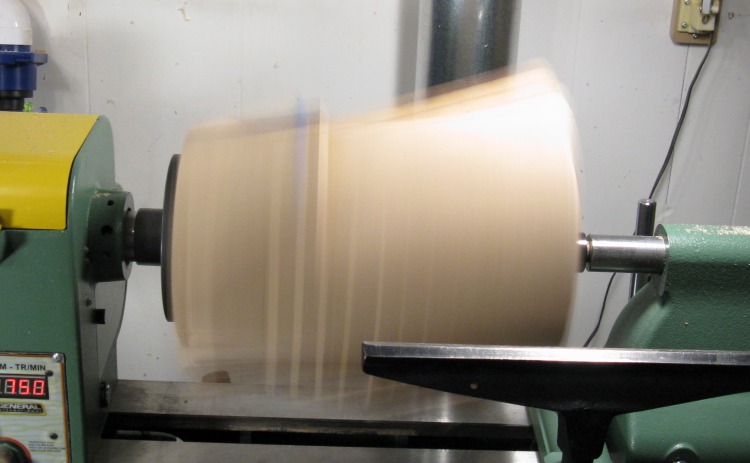
Ready for rounding
This rather dangerous-looking shot has the wood spun up to 750 RPM in preparation to start rounding.
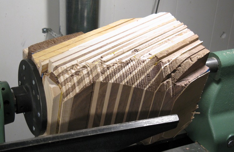
First corners removed
I stopped to check the removal of the first corners. I was using a roughing gouge and you can see the "bites" it takes.
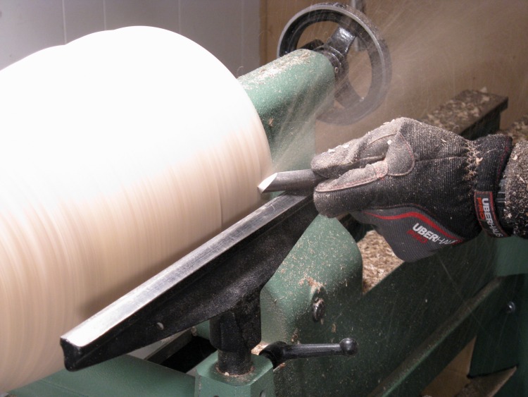
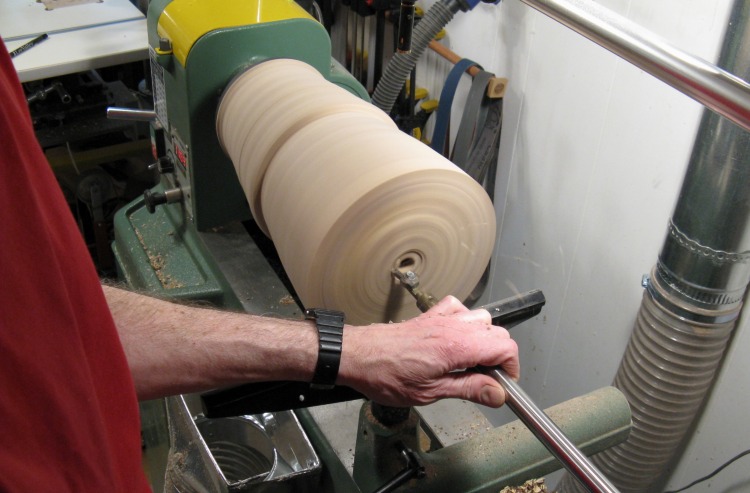
Reducing diameter
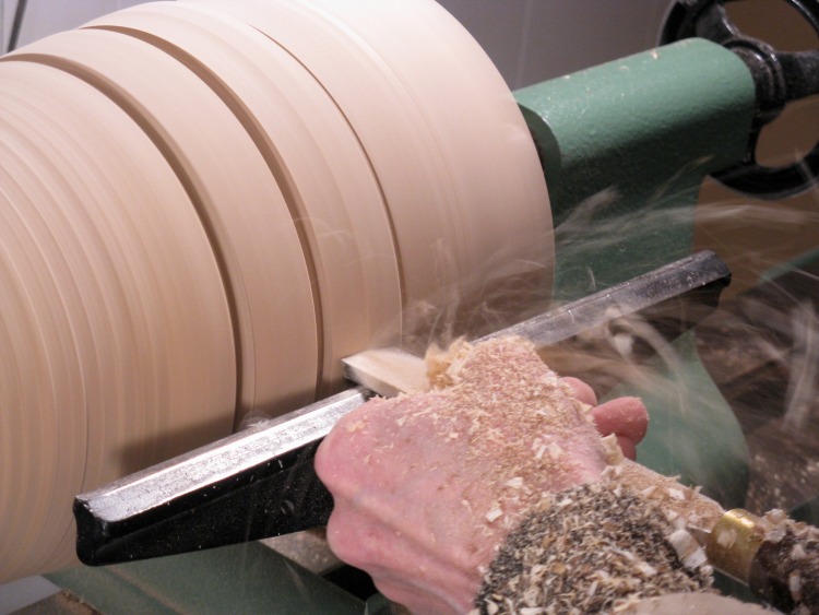
At this stage, most of the vessel is almost round and this shot shows me reducing the diameter at one end.
This particular gouge is quite handy, but it tends to shoot the wood a long way. Instead of a pile of chips around the lathe, I get shelves and other things in the shop covered.
This particular gouge is quite handy, but it tends to shoot the wood a long way. Instead of a pile of chips around the lathe, I get shelves and other things in the shop covered.

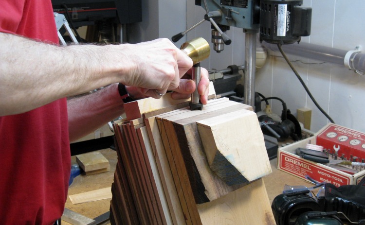
Checking diameter
When the size started getting close, it was time to break out the Big Calibers. The diameter is still larger than needed and I've cut in a narrow notch with the desired size. I'm setting the calipers to the resulting diameter and will take it over and compare to the desired size on a 1:1 scale drawing, then make the notch deeper if necessary.
This took a number of iterations since I changed the diameter only a "conservative" amount each time. I really didn't want to make it too small.
This took a number of iterations since I changed the diameter only a "conservative" amount each time. I really didn't want to make it too small.
Shaping with a scraper
In this photo you can see a number of diameter-calibration notches. After most of the extra wood was removed, the scraper was used to cut down to the desired diameters and then smooth the profile between those points.
Top half outside done
I shaped only the top half of the vessel to leave more wood on the bottom end for strength purposes.
There are some uneven edges at the top, but I planned to deal with them after the turning was complete.
There are some uneven edges at the top, but I planned to deal with them after the turning was complete.
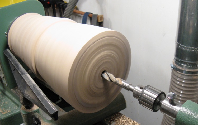
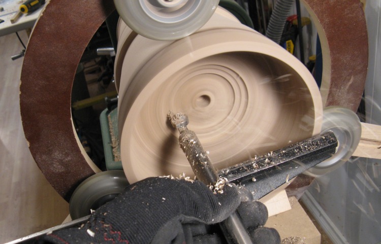
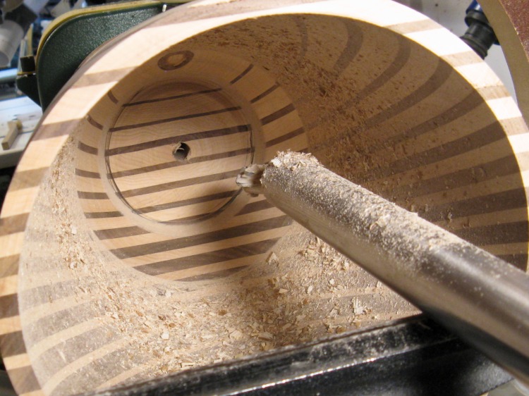
Drilling out the center
So then it was time to start the hollowing and the first thing to do was to drill out the center. I just drilled to the depth of the bit (maybe 5"), and then came back after some hollowing was done to make the hole deeper.
This picture seems odd to me with the wood spinning and the drill bit stopped, but hey - it works.
This picture seems odd to me with the wood spinning and the drill bit stopped, but hey - it works.
Starting the hollowing
Here I'm starting to cut away from the center hole using the captured hollowing jig with a small carbide bit. Click here for a few more details on the jig.
Unfortunately, the wood was starting to vibrate as I cut into it so that meant that it was too long to hollow without some additional support.
Unfortunately, the wood was starting to vibrate as I cut into it so that meant that it was too long to hollow without some additional support.
What I needed was a steady rest for the wood. I did have one, but it was too small for this size of vessel, so I needed to make a new appropriately-sized version. This little four-picture vignette shows that process.
I started with some 3/4" MDF that was a temporary table top I'd made years ago, and cut the frame from that. I used the wheels from my smaller unit, added some new mounting hardware and made some longish struts for them.
I started with some 3/4" MDF that was a temporary table top I'd made years ago, and cut the frame from that. I used the wheels from my smaller unit, added some new mounting hardware and made some longish struts for them.
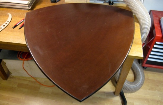
The sacrificial table top
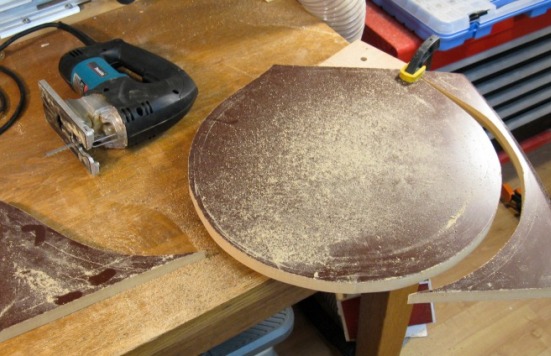
Cutting out the frame
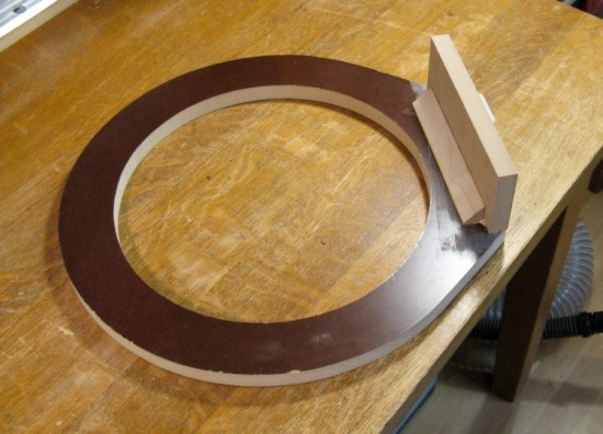
Mounting base added
Making wheel struts
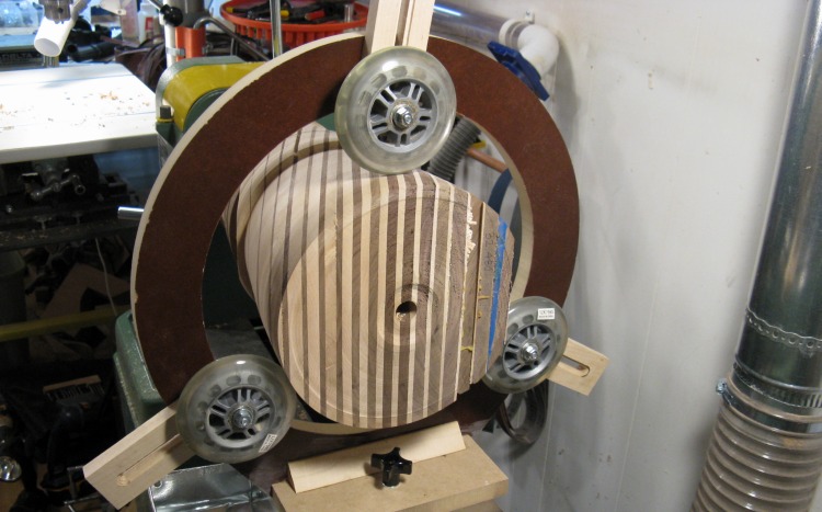
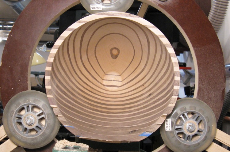
Steady rest holding vessel
And here is the result, already mounted on the lathe.
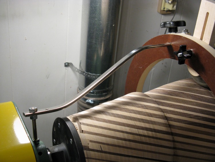
Anti-vibration strut
I found that the steady rest wasn't quite steady enough to prevent the frame flexing a bit, so I added a metal strut to stiffen it. It mounted to an existing hole in the lathe and with a clamp on the frame. It was pretty solid after that was in place.
First bit hollowed
I hollowed from the center to the outside in about 1/2" steps. Here the first couple of steps have been done.
Wider cutter
With the small size of the carbide cutter (which was maybe 0.2" diameter) I found it was difficult to make the inside wall smooth. So I reground a different (more plebeian high-speed steel) cutter to have a larger radius. This helped, but wall smoothness still wasn't great.
Working my way inside
I'm two or three inches in at this point. I used the cutter to take thin layers off, working outwards. The cutter is super-sharp and makes a very clean cut on the end grain.
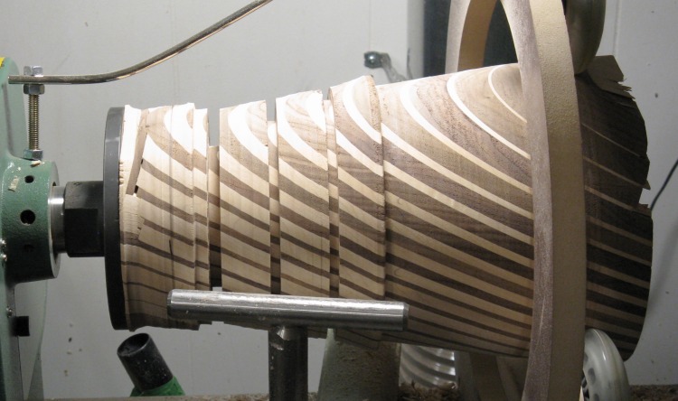
Size-guide notches for lower half
When I had hollowed as far in as the outside was finished, it was time to go back and do the shaping of the lower part of the outside of the vessel. Again I cut depth-guide notches about every 1.5"...
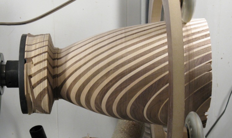
Most of the outside shaping done
...and smoothed between them to get to the final profile. The outside is now mostly shaped except for the lower inch or two.
And then it was back to the hollowing. I hadn't gotten any better at making a smooth inside wall so I decided that I needed an even wider cutter.
And then it was back to the hollowing. I hadn't gotten any better at making a smooth inside wall so I decided that I needed an even wider cutter.
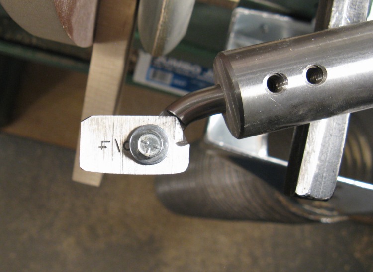
New wider cutter for inside
I started looking around the shop for some suitable piece of metal that could be sacrificed for the cause. Most were too soft, but a 3/4" spade-style drill bit caught my eye; about the right shape and thickness, hard enough and easy to replace.
So I spent about 5 or 10 minutes cutting the points and shaft off, grinding it to shape, and sharpening it. Then I just had to enlarge an already-existing hole by about 1/16" to accommodate the mounting screw. But the metal was as hard as...well...a drill bit, so I couldn't just drill a larger hole. I had to abrade a larger hole, which took about a half-hour and consumed three Dremel bits.
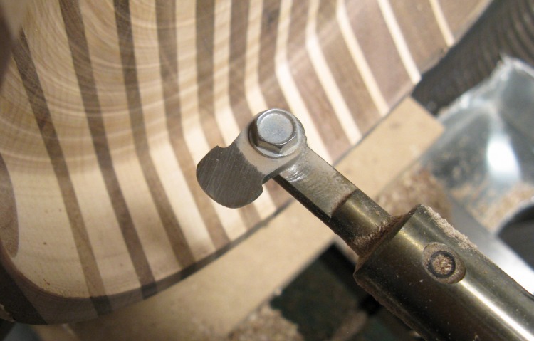
Ultimately I ended up with the cutter shown here with only a slight curve on the cutting edge. I mounted it on a curved holder so it would clear the 1" boring bar that I was using.
So I spent about 5 or 10 minutes cutting the points and shaft off, grinding it to shape, and sharpening it. Then I just had to enlarge an already-existing hole by about 1/16" to accommodate the mounting screw. But the metal was as hard as...well...a drill bit, so I couldn't just drill a larger hole. I had to abrade a larger hole, which took about a half-hour and consumed three Dremel bits.
Ultimately I ended up with the cutter shown here with only a slight curve on the cutting edge. I mounted it on a curved holder so it would clear the 1" boring bar that I was using.
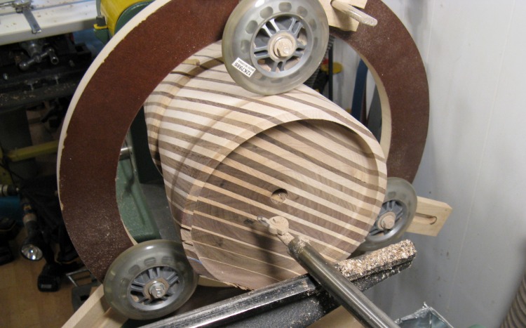
Smoothing the inside
In this photo, the inside has been smoothed with the new cutter for an inch or two from back. This worked great and the surface was much smoother.
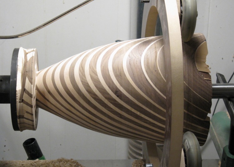
Outside shaping done
Once I had hollowed within a couple inches from the bottom, I went back and finished the last of the outside shaping at the bottom, with the final shape seen here.
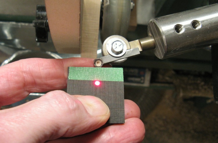
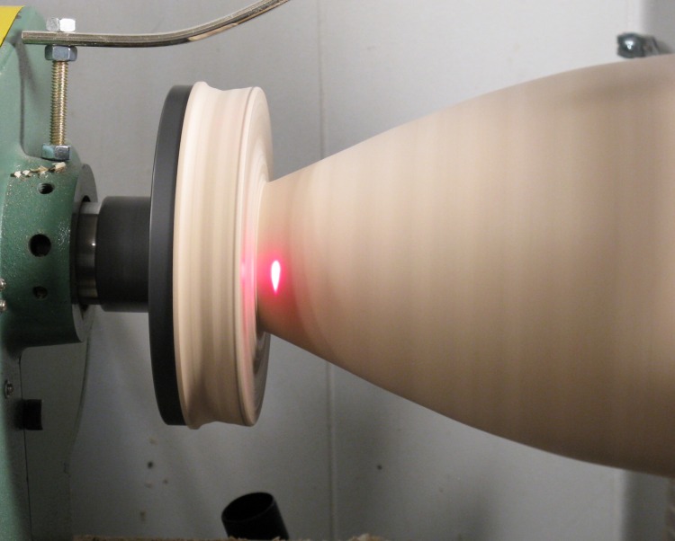
Setting the laser for wall thickness
I've sort of neglected the wall-thickness aspect of the turning, so this shows the laser being set to the desired wall thickness (based on the width of the green tape).
The hollowing jig came with a couple thicknesses of boring bar. I started with the 3/4" bar but switched to the 1" bar shown here for more rigidity after I had cut a few inches into the vessel.
The hollowing jig came with a couple thicknesses of boring bar. I started with the 3/4" bar but switched to the 1" bar shown here for more rigidity after I had cut a few inches into the vessel.
Laser showing cutter position
I didn't usually use the laser for cutting out the bulk of the center wood - I was mostly able to look into the vessel. But for purposes of illustration, here the laser dot shows that the position of the cutter is still a fair distance from the wall.
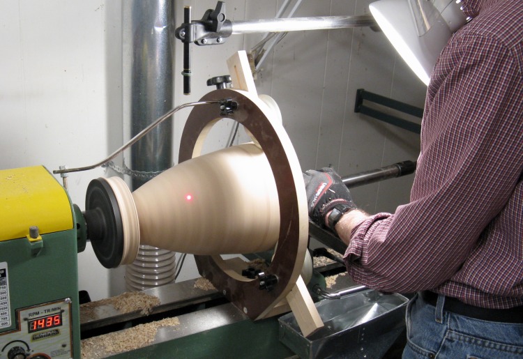
Hollowed all the way to the bottom
The laser guide was used whenever I was cutting close to the edge. At the time of this photo, the vessel is hollowed all the way to the bottom and the laser spot shows that the cutter is almost at the desired wall thickness.
Inside completed
The inside hollowing and wall smoothing is complete.
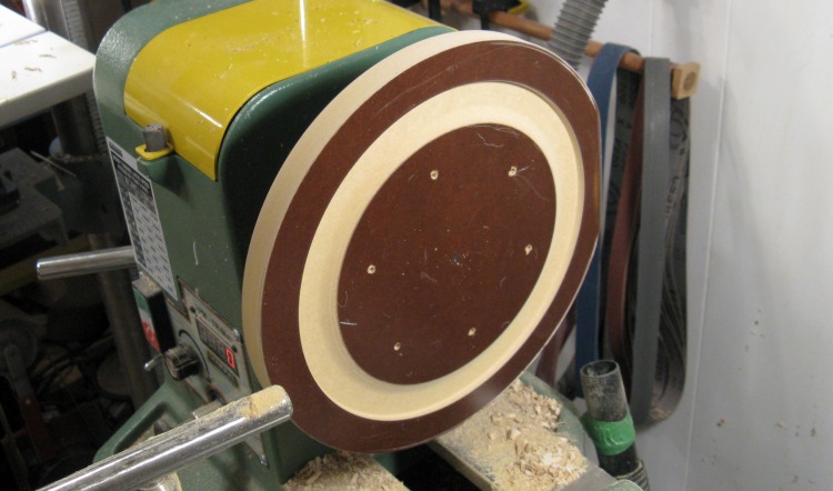
"Jam" chuck to hold top
The next step was to remove the large piece of wood attaching the vessel to the faceplate. This would be done by flipping the vessel around to get access to the bottom.
To hold the top, I made a jam chuck, which is a just a flat piece of wood with a slot the same diameter as the top of the vessel. The wall of the slot is slightly angled so the fit gets tighter as the vessel is pushed further in, to ensire a tight fit without having to have the perfect slot diameter. I just used another piece from the MDF tabletop to make the chuck.
To hold the top, I made a jam chuck, which is a just a flat piece of wood with a slot the same diameter as the top of the vessel. The wall of the slot is slightly angled so the fit gets tighter as the vessel is pushed further in, to ensire a tight fit without having to have the perfect slot diameter. I just used another piece from the MDF tabletop to make the chuck.
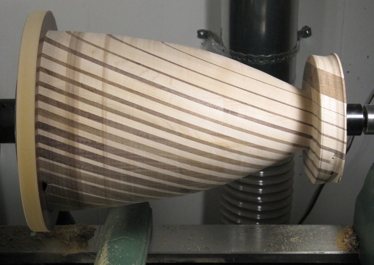
Remounted to do the bottom
After the vessel was taken off the lathe and had the faceplate removed, it was remounted to the lathe between the jam chuck and the live center.
Extra wood removed
While the vessel was off the lathe I measured and marked the inside depth on the outside to make sure I had the correct bottom thickness. This was the classic "measure twice, cut once" situation except I actually measured about 6 times. I really didn't want to risk cutting too high and having no bottom. At any rate, that is the little pencil line in this photo.
At this point the extra wood at the bottom has been cut away and the vessel bottom has been cut to an appropriate thickness.
At this point the extra wood at the bottom has been cut away and the vessel bottom has been cut to an appropriate thickness.
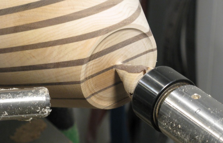
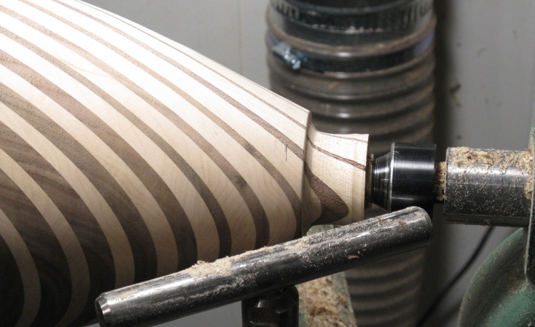
Bottom foot shaped
A circumferential foot was cut into the bottom and the central wood "axle" was narrowed to make it easier to remove.
Once off the lathe, the axle was cut off and the bottom sanded smooth.
Once off the lathe, the axle was cut off and the bottom sanded smooth.
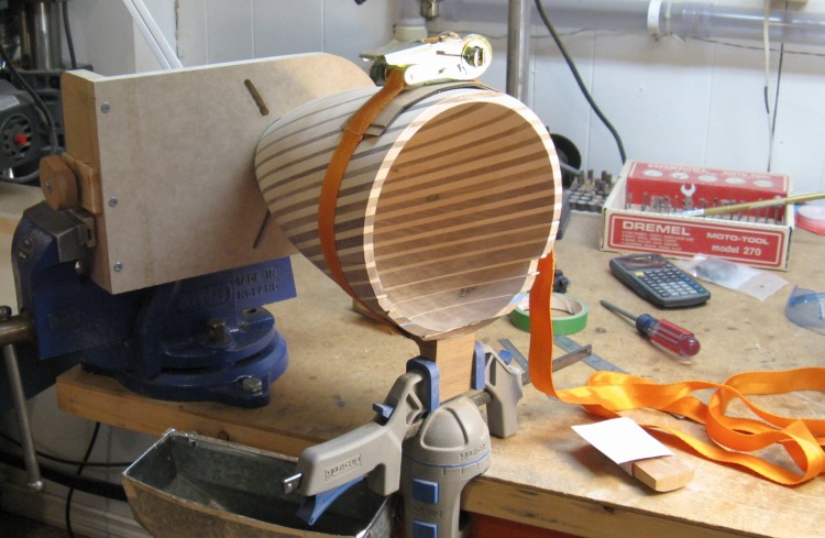
Inside sanding setup
In retrospect I should have sanded the inside of the vessel while still on the lathe before removing the faceplate. Oops. So instead, I got to kludge up a jig to hold it for sanding on the bench.
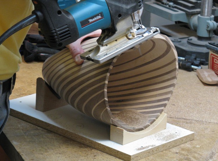
Cutting the top
I had thought to make the vessel with a contoured top edge, but I tried that out and didn't really like the look. So I recut it with a flat top. Normally this would be done on the lathe, but it was too late for that so I made a simple little jig to stabilize it and used a jigsaw to make the cut as shown here. The top edge was then sanded smooth.
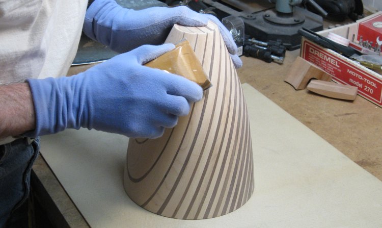
Sanding the outside
All that was left was the finish sanding of the outside, done by hand using a sanding block.
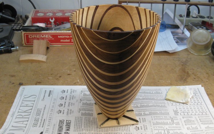
First coat of varnish
Here is the traditional first-coat-of-varnish shot.
And below the vessel shown from different angles.
And below the vessel shown from different angles.
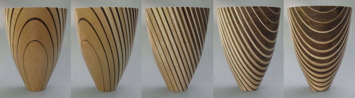
Views around the vessel


